Page 569 of 1807
P11288P11833A03032
TE1
E1
SST
DLC1
DI-154
- DIAGNOSTICSENGINE (2JZ-GTE)
382 Author�: Date�:
1997 SUPRA (RM502U)
6 Check ignition timing.
PREPARATION:
(a) Warm up engine to normal operating temperature.
(b) Shift transmission into ºNº position.
(c) Keep the engine speed at idle.
(d) Using SST, connect terminals TE1 and E1 of DLC 1.
SST 09843-18020
(e) Using a timing light, connect the tester to check wire
(See page EM-1 1).
CHECK:
Check ignition timing.
OK:
Ignition timing: 10 ± 2° BTDC at idle
NG Proceed to IG-1 and continue to
troubleshoot.
OK
Proceed to matrix chart of problem symp-
toms on page DI-169.
Page 582 of 1807

DI-167
395 Author�: Date�:
1997 SUPRA (RM502U) ISC4 (B32) - E01 (B80)
R-G e BRIdling, When A/C Switch ON or OFFPulse generation
(See page DI-240)
OX1 (B48) - E1 (B69)W")
- DIAGNOSTICSENGINE (2JZ-GTE)
DI-167
395 Author�: Date�:
1997 SUPRA (RM502U) ISC4 (B32) - E01 (B80)
R-G e BRIdling, When A/C Switch ON or OFFPulse generation
(See page DI-240)
OX1 (B48) - E1 (B69)W e BRMaintain engine speed at 2,500 rpm for 2 min. after warning upPulse generation
(See page DI-193)
OXS (B47) - E1 (B69)R-L e BRMaintain engine speed at 2,500 rpm for 2 min. after warning upPulse generation
(See page DI-193)
HT1 (B71) E01 (B80)BLBRIdling after warning upBelow 3.0HT1 (B71) - E01 (B80)B-L e BRIG switch ON9 - 14
HTS (B72) E01 (B80)BR WBRIdling after warning upBelow 3.0HTS (B72) - E01 (B80)BR-W e BRIG switch ON9 - 14
KNK1 (B50) - E1 (B69)W e BRIdlingPulse generation
(See page DI-212)
KNK2 (B49) - E1 (B69)W e BRIdlingPulse generation
(See page DI-212)
NSW (B76) E1 (B69)BWBR
IG switch ON
Other shift position in ºPº or ºNº position9 - 14
NSW (B76) - E1 (B69)B-W e BRIG switch ON
Shift position in ºPº or ºNº position0 - 3.0
SPD (A2) - E1 (B69)P e BRIG switch ON
Rotate driving wheel slowlyPulse generation
(See page DI-238)
TE1 (A20) - E1 (B69)L e BRIG switch ON9 - 14
W (A6) E1 (B69)LBBRIdling9 - 14W (A6) - E1 (B69)L-B e BRIG switch ON0 - 3.0
OD1 (A12) - E1 (B69)BR-B e BRIG switch ON9 - 14
AC1 (A34) E1 (B69)LRBRA/C switch ON (At idling)0 - 1.5AC1 (A34) - E1 (B69)L-R e BRA/C switch OFF7.5 - 14
ACMG (A23) E01 (B80)WGBRA/C switch ON (At idling)0 - 3.0ACMG (A23) - E01 (B80)W-G e BRA/C switch OFF9 - 14
FPU (B73) E01 (B80)WLBRIG switch ON9 - 14FPU (B73) - E01 (B80)W-L e BRRestarting at high engine coolant temp.Below 2.0
ELS (A15) E1 (B69)RYBRDefogger switch or taillight switch ON7.5 - 14ELS (A15) - E1 (B69)R-Y e BRDefogger switch and taillight switch OFF-0.1 - 1.5
SDL (A8) - E1 (B69)G e BRDuring transmissionPulse generation
VSV1 (B40) E1 (B69)GBBRImmediately after racingBelow 3.0VSV1 (B40) - E1 (B69)G-B e BRIdling9 - 14
VSV2 (B39) E1 (B69)GYBRFor 2 sec. after IG switch ON to OFFBelow 3.0VSV2 (B39) - E1 (B69)G-Y e BRIdling9 - 14
VSV3 (B38) - E1 (B69)B-Y e BRIdling9 - 14
VSV4 (B60) - E1 (B69)L-W e BR
Idling and other shift position ºPº or ºNº position (for A/T).
Idling (for M/T)Below 3.0VSV4 (B60) E1 (B69)LW e BR
Idling and shift position ºPº or ºNº position (for A/T)9 - 14
IG switch ON2.3 - 3.0
PIM1 (B62) - E2 (B65)B-Y e W-BIG switch ON and apply vacuum 26.7 kPa
(200 mm Hg, 7.9 in. Hg)1.0 - 1.5
EFI+ (A27) - E2 (B65)B e W-BIG switch ONPulse generation
(See page DI-285)
EFI- (A26) - E2 (B65)W e W-BIG switch ONPulse generation
(See page DI-285)
Page 587 of 1807
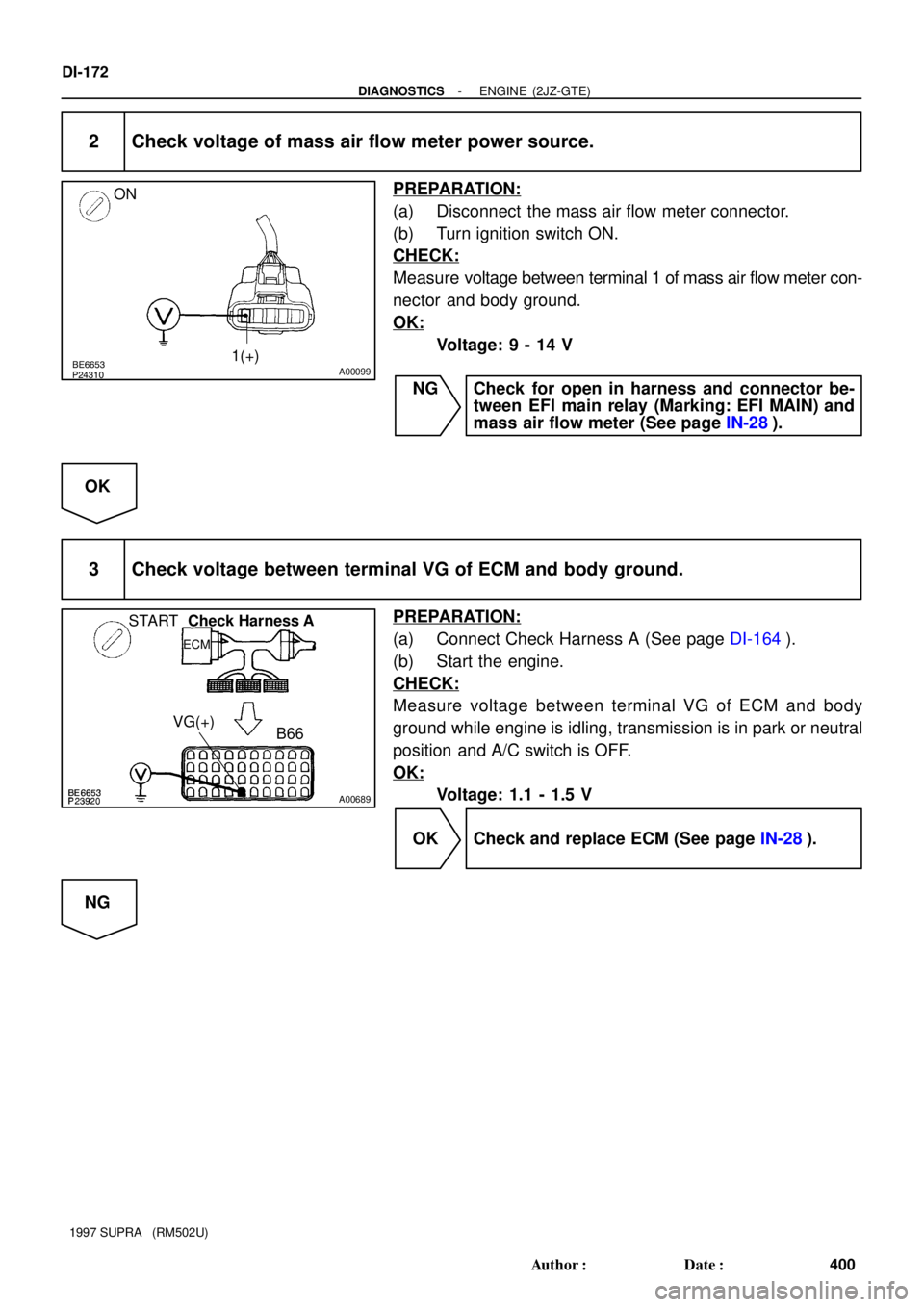
BE6653
P24310A00099
ON
1(+)
A00689
STARTCheck Harness A
ECM
B66 VG(+)
DI-172
- DIAGNOSTICSENGINE (2JZ-GTE)
400 Author�: Date�:
1997 SUPRA (RM502U)
2 Check voltage of mass air flow meter power source.
PREPARATION:
(a) Disconnect the mass air flow meter connector.
(b) Turn ignition switch ON.
CHECK:
Measure voltage between terminal 1 of mass air flow meter con-
nector and body ground.
OK:
Voltage: 9 - 14 V
NG Check for open in harness and connector be-
tween EFI main relay (Marking: EFI MAIN) and
mass air flow meter (See page IN-28).
OK
3 Check voltage between terminal VG of ECM and body ground.
PREPARATION:
(a) Connect Check Harness A (See page DI-164).
(b) Start the engine.
CHECK:
Measure voltage between terminal VG of ECM and body
ground while engine is idling, transmission is in park or neutral
position and A/C switch is OFF.
OK:
Voltage: 1.1 - 1.5 V
OK Check and replace ECM (See page IN-28).
NG
Page 651 of 1807

Q04361 FI6643A03136
T/M4-Pulse 4-Pulse
ECM
Combination
Meter No.1 Vehicle
Speed MeterTransmission
Output Shaft
Driven Gear
No.1 Vehicle Speed Sensor
S01080
GAUGE Fuse
23
II1
YY
Y
1
1
2No.1 Vehicle
Speed Sensor
Speed Meter3
L-R
II12
L-R5
Odometer and
Trip Meter
Telltale Light RH6
P11
II1P2
ASP1ECM
5V
E1 DI-238
- DIAGNOSTICSENGINE (2JZ-GTE)
466 Author�: Date�:
1997 SUPRA (RM502U)
DTC P0500 Vehicle Speed Sensor Malfunction
CIRCUIT DESCRIPTION
The No.1 vehicle speed senor outputs a 4-pulse signal for every revolution of the rotor shaft, which is rotated
by the transmission output shaft via the driven gear. After this signal is converted into a more precise rectan-
gular waveform by the waveform shaping circuit inside the combination meter, it is then transmitted to the
ECM. The ECM determines the vehicle speed based on the frequency of these pulse signals.
DTC No.DTC Detecting ConditionTrouble Area
P0500
No vehicle speed sensor signal to ECM under the following
conditions:
(2 trip detection logic)
(a) Park/neutral position switch is OFF
(b) Vehicle is being driven�Open or short in vehicle speed sensor circuit
�Vehicle speed sensor
�Combination meter
�ECM
WIRING DIAGRAM
DI4T7-01
Page 962 of 1807

PROBLEM SYMPTOMS TABLE
SymptomSuspect AreaSee page
Cruise control system does not set.
Cruise control syste")
DI4XP-01
- DIAGNOSTICSCRUISE CONTROL SYSTEM
DI-671
899 Author�: Date�:
1997 SUPRA (RM502U)
PROBLEM SYMPTOMS TABLE
SymptomSuspect AreaSee page
Cruise control system does not set.
Cruise control system does not operate.
Input signal check No.4: OK
1. ECU Power Source Circuit
2. Wire Harness
3. Main Switch Circuit
4. Control Switch Circuit
5. Stop Light Switch Circuit
6. PNP Switch or Clutch Switch Circuit
7. Actuator Control Cable
8. Actuator Motor Circuit
9. Cruise Control ECU
Input signal check No.4: NG
1. Vehicle Speed Sensor Circuit
2. Cruise Control ECU
DI-699
DI-704
DI-682
DI-687
DI-694,
DI-697
DI-710
DI-673
IN-28
DI-679
IIN-28
Indicator light does not light up.
1. Wire Harness
2. CRUISE MAIN Indicator Light Circuit
3. Cruise Control ECU
DI-706
IIN-28
Vehicle speed drop when the cruise control switch turned to SET.
1. Actuator Control Cable
2. ECU Power Source Circuit
3. Idle Signal Circuit
4. Actuator Motor Circuit
5. Cruise Control ECUDI-710
DI-699
DI-685
DI-673
IN-28
Set speed deviates on high or low side.
Input signal check No.4: OK
1. Vehicle Speed Sensor Circuit
2. Actuator Control Cable
3. ECU Power Source Circuit
4. Actuator Motor Circuit
5. Cruise Control ECU
Input signal check No.4: NG
1. Cruise Control ECU
DI-679
DI-710
DI-699
DI-673
IN-28
IN-28
Vehicle speed fluctuates when cruise control switch turn to SET.
1. Vehicle Speed Sensor Circuit
2. Actuator Control Cable
3. Idle Signal Circuit
4. ECT Communication Circuit
5. Actuator Motor Circuit
6. Cruise Control ECUDI-679
DI-710
DI-685
DI-690
DI-673
IN-28
Acceleration response is sluggish when cruise control switch turn
to ºACCELº or ºRESUMEº.
Input signal check No.4: OK
1. Actuator Control Cable
2. Vehicle Speed Sensor Circuit
3. Actuator Motor Circuit
4. Cruise Control ECU
Input signal check No.4: NG
1. Control Switch Circuit
2. Cruise Control ECU
DI-673
DI-679
DI-710
IN-28
DI-682
IN-28
Set speed does not cancel when brake pedal depressed.
Input signal check No.3: OK
1. Cruise Control ECU
Input signal check No.3: NG
1. Stop Light Switch Circuit
2. Cruise Control ECU
IN-28
DI-687
IIN-28
Cruise control does not cancel when transmission is shifted to
except D position. (A/T)
Input signal check No.3: OK
1. Cruise Control ECU
Input signal check No.3: NG
1. PNP Switch Circuit
2. Cruise Control ECU
IIN-28
DI-694
IN-28
Page 981 of 1807

R-L
(A/T) OD1
S2
*1: 2JZ-GTE Engine
*2: 2JZ-GE Engine R-L
(A/T)R-L
(A/T)
Electronically Controll")
N19614
ECM
E10
E9IJ2
IJ2C16
C16
E2
E2 12
9
8
2229 11
10Cruise Control ECU
OD
ECT BR-B*1LG-B
LG-B*1(A/T)
R-L
(A/T) OD1
S2
*1: 2JZ-GTE Engine
*2: 2JZ-GE Engine R-L
(A/T)R-L
(A/T)
Electronically Controlled Transmission Solenoid*1
*2
S2 DI-690
- DIAGNOSTICSCRUISE CONTROL SYSTEM
918 Author�: Date�:
1997 SUPRA (RM502U)
Electronically Controlled Transmission Communication Circuit
CIRCUIT DESCRIPTION
When driving uphill under cruise control, in order to reduce shifting due to ON-OFF overdrive operation and
to provide smooth driving, when down shifting in the electronically controlled transmission occurs, a signal
to prevent upshift until the end of the uphill slope is sent from the cruise control ECU to the electronically
controlled transmission.
Terminal ECM of the cruise control ECU detects the shift change signal (output to electronically controlled
transmission No.2 solenoid) from the electronically controlled transmission.
If vehicle speed down, also when terminal electronically controlled transmission of the cruise control ECU
receive down shifting signal, it sends a signal from terminal OD to ECM to cut overdrive until the end of the
uphill slope, and the gear shifts are reduced and gear shift points in the electronically controlled transmission
are changed.
WIRING DIAGRAM
DI4XY-01
Page 982 of 1807
I02724
ON
(-)
OD (+)
- DIAGNOSTICSCRUISE CONTROL SYSTEM
DI-691
919 Author�: Date�:
1997 SUPRA (RM502U)
INSPECTION PROCEDURE
1 Check operation of overdrive.
PREPARATION:
Test drive after engine warms up.
CHECK:
Check that overdrive ON e OFF occurs with operation of OD switch ON e OFF.
NG Check and repair electronically controlled
transmission (See page DI-371).
OK
2 Check voltage between terminal OD of harness side connector of cruise control
ECU and body ground.
PREPARATION:
Remove cruise control ECU with connector still connected.
CHECK:
(a) Disconnect cruise control ECU connector.
(b) Turn ignition switch ON.
(c) Measure voltage between terminal OD of harness side
connector of cruise control ECU and body ground.
OK:
Voltage: 10 - 14 V
NG Go to step 5.
OK
Page 983 of 1807
N19837
(-)ECT (+)
DI-692
- DIAGNOSTICSCRUISE CONTROL SYSTEM
920 Author�: Date�:
1997 SUPRA (RM502U)
3 Check voltage between terminal ECT of cruise control ECU connector and body
ground (On test drive).
PREPARATION:
(a) Connect cruise control ECU connector.
(b) Test drive after engine warms up.
CHECK:
Check voltage between terminal ECT of cruise control ECU
connector and body ground when OD switch is ON and OFF.
OK:
OD switch positionVoltage
ON8 - 14 V
OFFBelow 0.5 V
OK Proceed to next circuit inspection shown on
problem symptoms table (See page DI-671).
NG
4 Check harness and connector between terminal ECT of cruise control ECU and
electronically controlled transmission solenoid (See page IN-28).
NG Repair or replace harness or connector.
OK
Check and replace cruise control ECU.