Page 1282 of 1807
EM0AG-02
Z13597
Air Cleaner and
MAF Meter AssemblyNo.1 Air Hose
Engine Wire Protector
Air Cleaner Duct
Theft Deterrent Horn
Drive Belt
No.5 Air Hose
Hose Clamp
Oil Cooler Tube (A/T)
Hose Clamp
Front Lower Arm
Bracket Stay
Upper Crossmember
Extension
Engine Under CoverNo.2 Front Exhaust PipeHeat Insulator
Pipe Support BracketEVAP Hose
Brake Booster
Vacuum Hose
Tube Clamp
� Gasket
��� Gasket
x 16
� Non-reusable part
- ENGINE MECHANICAL (2JZ-GTE)CYLINDER HEAD
EM-25
1130 Author�: Date�:
1997 SUPRA (RM502U)
CYLINDER HEAD
COMPONENTS
Page 1421 of 1807

MA01E-01
MA-2
- MAINTENANCEINSIDE VEHICLE
39 Author�: Date�:
1997 SUPRA (RM502U)
INSIDE VEHICLE
GENERAL MAINTENANCE
These are maintenance and inspection items which are considered to be the owner's responsibility.
They can be done by the owner or they can have them done at a service shop.
These items include those which should be checked on a daily basis, those which, in most cases, do not
require (special) tools and those which are considered to be reasonable for the owner to do.
Items and procedures for general maintenance are as follows.
1. GENERAL NOTES
�Maintenance items may vary from country to country. Check the owner's manual supplement in which
the maintenance schedule is shown.
�Every service item in the periodic maintenance schedule must be performed.
�Periodic maintenance service must be performed according to whichever interval in the periodic main-
tenance schedule occurs first, the odometer reading (miles) or the time interval (months).
�Maintenance service after the last period should be performed at the same interval as before unless
otherwise noted.
�Failure to do even one item an cause the engine to run poorly and increase exhaust emissions.
2. LIGHTS
(a) Check that the headlights, stop lights, taillights, turn signal lights, and other lights are all working.
(b) Check the headlight aim.
3. WARNING LIGHTS AND BUZZERS
Check that all warning lights and buzzers function properly.
4. HORN
Check that it is working.
5. WINDSHIELD GLASS
Check for scratches, pits or abrasions.
6. WINDSHIELD WIPER AND WASHER
(a) Check operation of the wipers and washer.
(b) Check that the wipers do not streak.
7. WINDSHIELD DEFROSTER
Check that air comes out from the defroster outlet when operating the heater or air conditioner.
8. REAR VIEW MIRROR
Check that it is mounted securely.
9. SUN VISORS
Check that they move freely and are mounted securely.
10. STEERING WHEEL
Check that it has the specified freeplay. Be alert for changes in steering condition, such as hard steering,
excessive freeplay or strange noises.
11. SEATS
(a) Check that the seat adjusters operate smoothly.
(b) Check that all latches lock securely in any position.
(c) Check that the head restraints move up and down smoothly and that the locks hold securely in any
latch position.
(d) For fold-down seat backs, check that the latches lock securely.
12. SEAT BELTS
(a) Check that the seat belt system such as the buckles, retractors and anchors operate properly and
smoothly.
(b) Check that the belt webbing is not cut, frayed, worn or damaged.
Page 1435 of 1807

RS0OM-01
- SUPPLEMENTAL RESTRAINT SYSTEMSTEERING WHEEL PAD AND SPIRAL CABLE
RS-9
1948 Author�: Date�:
1997 SUPRA (RM502U)
INSPECTION
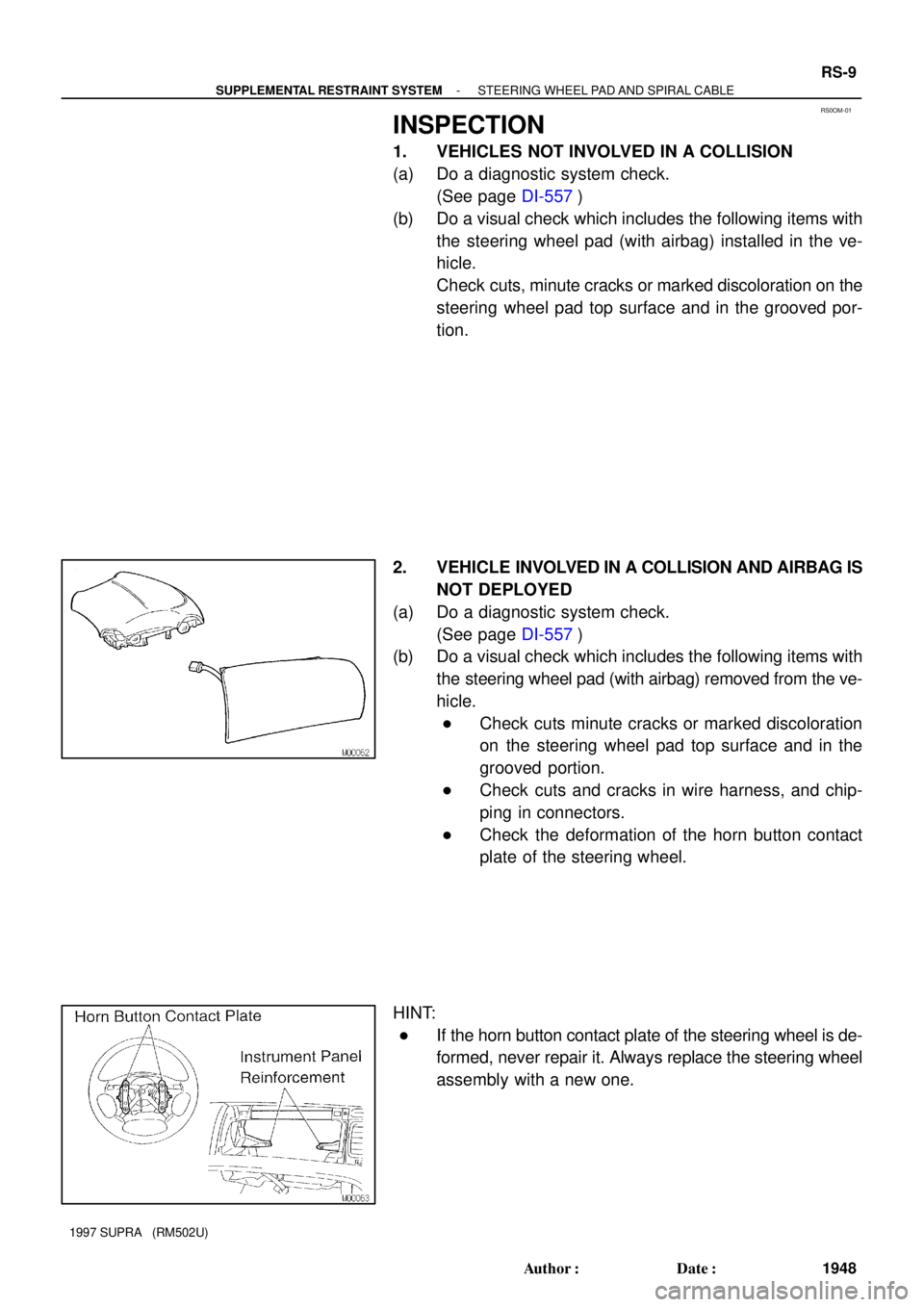
1. VEHICLES NOT INVOLVED IN A COLLISION
(a) Do a diagnostic system check.
(See page DI-557)
(b) Do a visual check which includes the following items with
the steering wheel pad (with airbag) installed in the ve-
hicle.
Check cuts, minute cracks or marked discoloration on the
steering wheel pad top surface and in the grooved por-
tion.
2. VEHICLE INVOLVED IN A COLLISION AND AIRBAG IS
NOT DEPLOYED
(a) Do a diagnostic system check.
(See page DI-557)
(b) Do a visual check which includes the following items with
the steering wheel pad (with airbag) removed from the ve-
hicle.
�Check cuts minute cracks or marked discoloration
on the steering wheel pad top surface and in the
grooved portion.
�Check cuts and cracks in wire harness, and chip-
ping in connectors.
�Check the deformation of the horn button contact
plate of the steering wheel.
HINT:
�If the horn button contact plate of the steering wheel is de-
formed, never repair it. Always replace the steering wheel
assembly with a new one.
Page 1436 of 1807

RS-10
- SUPPLEMENTAL RESTRAINT SYSTEMSTEERING WHEEL PAD AND SPIRAL CABLE
1949 Author�: Date�:
1997 SUPRA (RM502U)
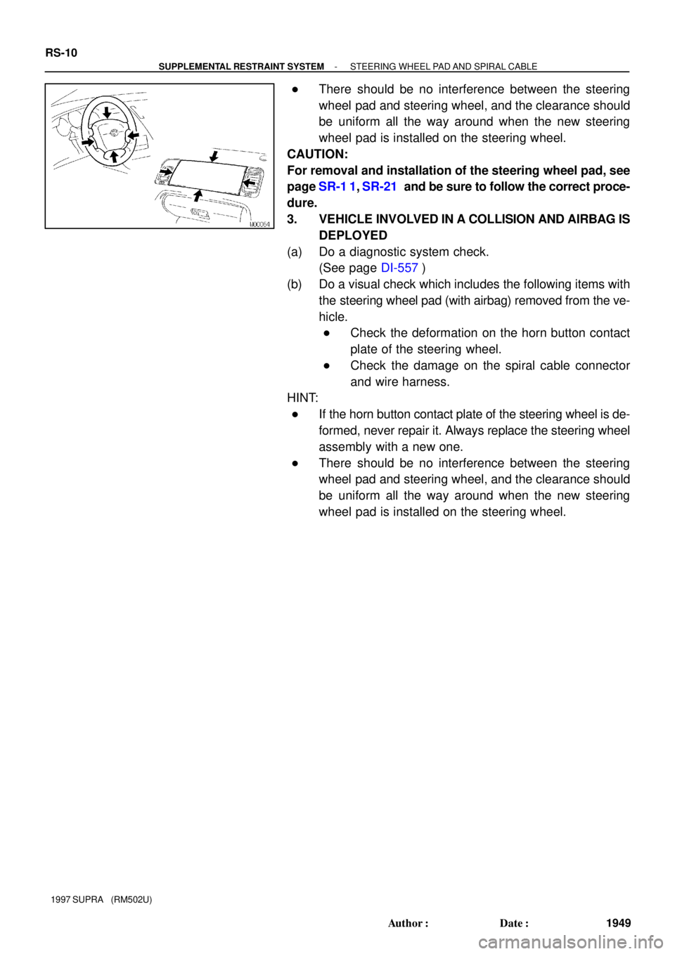
�There should be no interference between the steering
wheel pad and steering wheel, and the clearance should
be uniform all the way around when the new steering
wheel pad is installed on the steering wheel.
CAUTION:
For removal and installation of the steering wheel pad, see
page SR-1 1, SR-21 and be sure to follow the correct proce-
dure.
3. VEHICLE INVOLVED IN A COLLISION AND AIRBAG IS
DEPLOYED
(a) Do a diagnostic system check.
(See page DI-557)
(b) Do a visual check which includes the following items with
the steering wheel pad (with airbag) removed from the ve-
hicle.
�Check the deformation on the horn button contact
plate of the steering wheel.
�Check the damage on the spiral cable connector
and wire harness.
HINT:
�If the horn button contact plate of the steering wheel is de-
formed, never repair it. Always replace the steering wheel
assembly with a new one.
�There should be no interference between the steering
wheel pad and steering wheel, and the clearance should
be uniform all the way around when the new steering
wheel pad is installed on the steering wheel.
Page 1790 of 1807
TC00D-02
P20891
No.1 Air Hose
Air Cleaner
and MAF Meter
Assembly
Tube Bracket
�Non-reusable Air Cleaner Duct
Theft Deterrent Horn
Tube Clamp
A/T Oil Cooler TubeMAF Meter Connector
Engine Wire Protector
Cruise Control
Actuator Cable
Heat Insulator
for No.2 Front
Exhaust Pipe
Pipe Support Bracket�Gasket
Tube ClampFront Lower Arm
Bracket Stay
Engine Under CoverUpper Front
Crossmember
ExtensionNo.2 Front
Exhaust Pipe
�Gasket
x 16�
��
- TURBOCHARGING (2JZ-GTE)TURBOCHARGER
TC-7
1207 Author�: Date�:
1997 SUPRA (RM502U)
COMPONENTS
Page 1793 of 1807

TC00E-02
P11430
ClampWire
P11348Arm Bracket Stay
Crossmember
Extension
P12054
TC-10
- TURBOCHARGING (2JZ-GTE)TURBOCHARGER
1210 Author�: Date�:
1997 SUPRA (RM502U)
REMOVAL
1. DRAIN ENGINE COOLANT
2. REMOVE ENGINE UNDER COVER
3. DISCONNECT CRUISE CONTROL ACTUATOR
CABLE FROM THROTTLE BODY
4. REMOVE NO.1 AIR HOSE
5. REMOVE AIR CLEANER DUCT
6. REMOVE AIR CLEANER AND MAF METER
ASSEMBLY
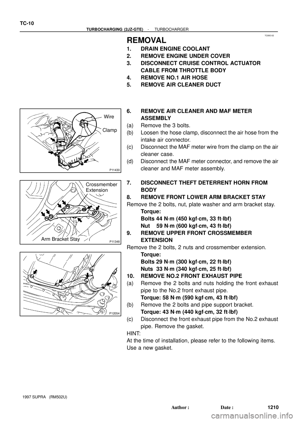
(a) Remove the 3 bolts.
(b) Loosen the hose clamp, disconnect the air hose from the
intake air connector.
(c) Disconnect the MAF meter wire from the clamp on the air
cleaner case.
(d) Disconnect the MAF meter connector, and remove the air
cleaner and MAF meter assembly.
7. DISCONNECT THEFT DETERRENT HORN FROM
BODY
8. REMOVE FRONT LOWER ARM BRACKET STAY
Remove the 2 bolts, nut, plate washer and arm bracket stay.
Torque:
Bolts 44 N´m (450 kgf´cm, 33 ft´lbf)
Nut 59 N´m (600 kgf´cm, 43 ft´lbf)
9. REMOVE UPPER FRONT CROSSMEMBER
EXTENSION
Remove the 2 bolts, 2 nuts and crossmember extension.
Torque:
Bolts 29 N´m (300 kgf´cm, 22 ft´lbf)
Nuts 33 N´m (340 kgf´cm, 25 ft´lbf)
10. REMOVE NO.2 FRONT EXHAUST PIPE
(a) Remove the 2 bolts and nuts holding the front exhaust
pipe to the No.2 front exhaust pipe.
Torque: 58 N´m (590 kgf´cm, 43 ft´lbf)
(b) Remove the 2 bolts and pipe support bracket.
Torque: 43 N´m (440 kgf´cm, 32 ft´lbf)
(c) Disconnect the front exhaust pipe from the No.2 exhaust
pipe. Remove the gasket.
HINT:
At the time of installation, please refer to the following items.
Use a new gasket.