Page 906 of 1807

PROBLEM SYMPTOMS TABLE
Proceed to the reference page shown in the matrix chart below for each malfunction")
DI4X0-01
- DIAGNOSTICSTHEFT DETERRENT SYSTEM
DI-615
843 Author�: Date�:
1997 SUPRA (RM502U)
PROBLEM SYMPTOMS TABLE
Proceed to the reference page shown in the matrix chart below for each malfunction symptom and trouble-
shoot for each circuit.
HINT:
Troubleshooting of the theft deterrent system is based on the premise that the door lock control system is
operating normally. Accordingly, before troubleshooting the theft deterrent system, first make certain that
the door lock control system is operating normally.
Theft Deterrent System:
Details of ProblemInspecting Circuit *1See page
1. Indicator light circuitDI-617
2. Luggage compartment door key lock and unlock switch
circuitDI-633
The theft deterrent system cannot be set3. Luggage compartment door courtesy switch circuitDI-636
4. Door courtesy switch circuitDI-640
5. Engine hood courtesy switch circuitDI-642
The indicator light does not blink when system is setIndicator light circuitDI-617
�When the system is set
�When the back door is opened by a method other than the key
�The system does not operate
Luggage compartment door courtesy switch circuitDI-636
�When the system is set
�When the engine hood is opened
�The system does not operate
Engine hood courtesy switch circuitDI-642
�While the system is in warning operation
�Horns do not soundHorn relay circuitDI-621
�While the system is in warning operation
�Theft deterrent horn does not soundTheft deterrent horn circuitDI-623
�While the system is in warning operation
�Headlights do not flashHeadlight control relay circuitDI-626
�While the system is in warning operation
�Taillights do not flashTaillight control relay circuitDI-628
�While the system is in warning operation
�The starter cut is not cut offStarter relay circuitDI-619
�When the system is set
�It is not canceled when the ignition key is turned to ACC or ON
position
Ignition switch circuitDI-630
�When the system is set
�It still operates when the back door is opened with the keyLuggage compartment door key lock and unlock switch
circuitDI-633
System is still set even when a rear door is openDoor courtesy switch circuitDI-640
�Even when the system is not set
�Horns soundHorn relay circuitDI-621
�Even when the system is not set
�Theft deterrent horn soundsTheft deterrent horn circuitDI-623
�Even when the system is not set
�Headlights stay onHeadlight control relay circuitDI-626
�Even when the system is not set
�Taillights stay onTaillight control relay circuitDI-628
*1:
If numbers are given to the circuit proceed with troubleshooting in the order indicated by those numbers.
Page 912 of 1807
I02710
I02710
Theft Deterrent and
Door Lock ECU R/B No.2
HORN Relay
R/B No2.Horn Switch
HornL-R
L-B HAZ-HORN
BatteryHORN
L-BL-R
L-R W
22
2 2
2
2A 11
1116
14
L-R
L-B 3IB2IF2
24
BT13
- DIAGNOSTICSTHEFT DETERRENT SYSTEM
DI-621
849 Author�: Date�:
1997 SUPRA (RM502U)
Horn Relay Circuit
CIRCUIT DESCRIPTION
When the theft deterrent system is activated, it causes the Tr in the ECU to switch on and off in approximately
0.2 sec. cycles. This switches the horn relay on and off, thus the horn blow (See the wiring diagram below).
In this condition, if any of the following operations is done, the Tr in the ECU goes off and the horn relay
switches off, thus the horns stop blowing:
(1) The front LH or RH door is unlocked with a key.
(2) The ignition switch is turned to the ACC or ON position.
(3) Approximately 1 minute elapses.
WIRING DIAGRAM
DI4X3-01
Page 913 of 1807
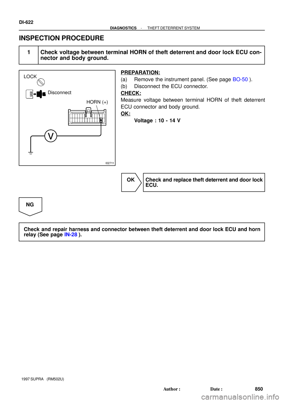
I02711
LOCK
Disconnect
HORN (+)
DI-622
- DIAGNOSTICSTHEFT DETERRENT SYSTEM
850 Author�: Date�:
1997 SUPRA (RM502U)
INSPECTION PROCEDURE
1 Check voltage between terminal HORN of theft deterrent and door lock ECU con-
nector and body ground.
PREPARATION:
(a) Remove the instrument panel. (See page BO-50).
(b) Disconnect the ECU connector.
CHECK:
Measure voltage between terminal HORN of theft deterrent
ECU connector and body ground.
OK:
Voltage : 10 - 14 V
OK Check and replace theft deterrent and door lock
ECU.
NG
Check and repair harness and connector between theft deterrent and door lock ECU and horn
relay (See page IN-28).
Page 914 of 1807
N09783
2
2AEA1II1
IB6 IF219 622
7
1
2
1
BatteryR/B No.2
HAZ-HORNW
(2JZ-GE)Theft Deterrent and
Door Lock ECU T13
(2JZ-GE)
11
(2JZ-GTE)
Theft Deterrent
Horn (2JZ-GTE)
BP-B W
WW-LW-L
SHa
b P-B
W-L
- DIAGNOSTICSTHEFT DETERRENT SYSTEM
DI-623
851 Author�: Date�:
1997 SUPRA (RM502U)
Theft Deterrent Horn Circuit
CIRCUIT DESCRIPTION
When the theft deterrent system is activated, contact ºaº and contact ºbº in the ECU close alternately in cycles
of approximately 0.2 sec., causing the theft deterrent horn to blow (See the wiring diagram below).
In this condition, if any of the following operations is done, the contact ºaº in the ECU opens, thus stopping
the theft deterrent horn from blowing:
(1) The front LH or RH door is unlocked with a key.
(2) The ignition switch is turned to the ACC or ON position.
(3) Approximately 1 minute elapses.
WIRING DIAGRAM
DI4X4-01
Page 915 of 1807
I02542
LOCK
Disconnect
2JZ-GE
2JZ-GTE2 (+)
2 (+)
N14682
1 (+)
2 (-)
DI-624
- DIAGNOSTICSTHEFT DETERRENT SYSTEM
852 Author�: Date�:
1997 SUPRA (RM502U)
INSPECTION PROCEDURE
1 Check voltage between terminal SH of theft deterrent horn connector and body
ground.
PREPARATION:
Remove the theft deterrent horn and disconnect the connector.
CHECK:
Measure voltage between terminal 1 of theft deterrent horn
connector and body ground.
OK:
Voltage : 10 - 14 V
NG Check and repair harness and connector be-
tween HORN fuse and theft deterrent horn.
OK
2 Check theft deterrent horn.
CHECK:
Connect positive � lead to terminal 1 and negative � lead to
terminal 2 of theft deterrent horn connector.
OK:
Theft deterrent horn blows.
NG Replace theft deterrent horn.
OK
Page 916 of 1807
- DIAGNOSTICSTHEFT DETERRENT SYSTEM
DI-625
853 Author�: Date�:
1997 SUPRA (RM502U)
3 Check harness and connector between theft deterrent and door lock ECU and
theft deterrent horn (See page IN-28).
NG Check and repair harness or connector.
OK
Check and replace theft deterrent ECU.
Page 1016 of 1807

17
E GLOSSARY OF TERMS AND SYMBOLS
METER, ANALOG
Current flow activates a magnetic
coil which causes a needle to
move, thereby providing a relative
display against a background
calibration. LED (LIGHT EMITTING DIODE)
Upon current flow, these diodes
emit light without producing the
heat of a comparable light. IGNITION COIL
Convert low-voltage DC current
into high-voltage ingition current
for firing the spark plugs.
1. SINGLE
FILAMENT
GROUND
The point at which wiring attaches
to the Body, thereby providing a
return path for an electrical circuit;
without a ground, current cannot
flow.
Current flow causes a headlight
filament to heat up and emit light.
A headlight may have either a
single (1) filament or a double (2)
filament. BATTERY
Stores chemical energy and
converts it into electrical energy.
Provides DC current for the
auto's various electrical circuits.
CAPACITOR (Condenser)
A small holding unit for temporary
storage of electrical voltage.
CIRCUIT BREAKER
Basically a reusable fuse, a circuit
breaker will heat and open if too
much current flows through it.
Some units automatically reset when
cool, others must be manually reset.
DIODE
A semiconductor which allows
current flow in only one direction.
DIODE, ZENER
A diode which allows current
flow in one direction but blocks
reverse flow only up to a specific
voltage. Above that potential, it
passes the excess voltage.
This acts as a simple voltage
regulator.
PHOTODIODE
The photodiode is a
semiconductor which controls the
current flow according to the
amount of light.
FUSE
A thin metal strip which burns
through when too much current
flows through it, thereby stop-
ping current flow and protecting a
circuit from damage.
FUSIBLE LINK
A heavy-gauge wire placed in
high amperage circuits which
burns through on overloads,
thereby protecting the circuit.
The numbers indicate the cross-
section surface area of the wires.HORN
An electric device which sounds a
loud audible signal.
LIGHT
Current flow through a filament
causes the filament to heat up
and emit light.
METER, DIGITAL
Current flow activates one or
many LED's, LCD's, or fluoresent
displays, which provide a relative
or digital display.
MOTOR
A power unit which converts
electrical energy into mechanical
energy, especially rotary motion. CIGARETTE LIGHTER
An electric resistance heating
element.
DISTRIBUTOR, IIA
Channels high-voltage current
from the ignition coil to the
individual spark plugs.
2. DOUBLE
FILAMENT
HEADLIGHTS
FUEL
M
(for High Current Fuse or
Fusible Link.)
(for Medium Current Fuse)
Page 1024 of 1807

Position of Parts in Engine Compartment
E 4 Engine Coolant Temp. Sender
E 5 Engine Coolant Temp. SW
E 6 Engine Hood Courtesy SW
E 7 Engine Oil Level Sensor
F 3 Front Fog Light LH
F 4 Front Fog Light RH
F 5 Front Side Marker Light LH
F 6 Front Side Marker Light RH
F 7 Front Turn Signal Light LH
F 8 Front Turn Signal Light RH and Parking Light RH
F 9 Front Wiper Motor
G 1 Generator
G 2 Generator
H 1 Headlight Hi LH
H 2 Headlight Hi RH
H 3 Headlight Lo LH
H 4 Headlight Lo RH
H 5 Heated Oxygen Sensor (Bank 1 Sensor 1)
H 8 Horn LH
H 9 Horn RH A 1 A/C Ambient Temp Sensor
A 2 A/C Condensor Fan Motor
A 3 A/C Triple Pressure SW
(A/C Dual and Single Pressure SW)
A 4 A/C Magnetic Clutch and Lock Sensor
A 5 A/T Fluid Temp. Sensor
A 6 ABS Actuator
A 7 ABS Actuator
A10 ABS Speed Sensor Front LH
A11 ABS Speed Sensor Front RH
B 1 Back-Up Light SW (M/T)
B 2 Brake Fluid Level Warning SW
C 1 Camshaft Position Sensor No.1
C 2 Camshaft Position Sensor No.2
C 3 Crankshaft Position Sensor
C 4 Cruise Control Actuator
D 1 Data Link Connector 1
D 2 Daytime Running Light Relay No.3
D 3 Daytime Running Light Relay No.3
E 1 EGR Gas Temp. Sensor
E 2 Electronically Controlled Transmission Solenoid
E 3 Engine Coolant Temp. Sensor
[2JZ-GTE]
24
26
G ELECTRICAL WIRING ROUTING

Theft Deterrent and
Door Lock ECU T13
(2JZ-GE)
11
(2JZ-GTE)
Theft Deterrent
Horn (2JZ-GTE)
BP-B W
WW-LW-L
SHa
b P-B
W-L
- DIAG")