Page 696 of 1807
- DIAGNOSTICSENGINE (2JZ-GTE)
DI-281
509 Author�: Date�:
1997 SUPRA (RM502U)
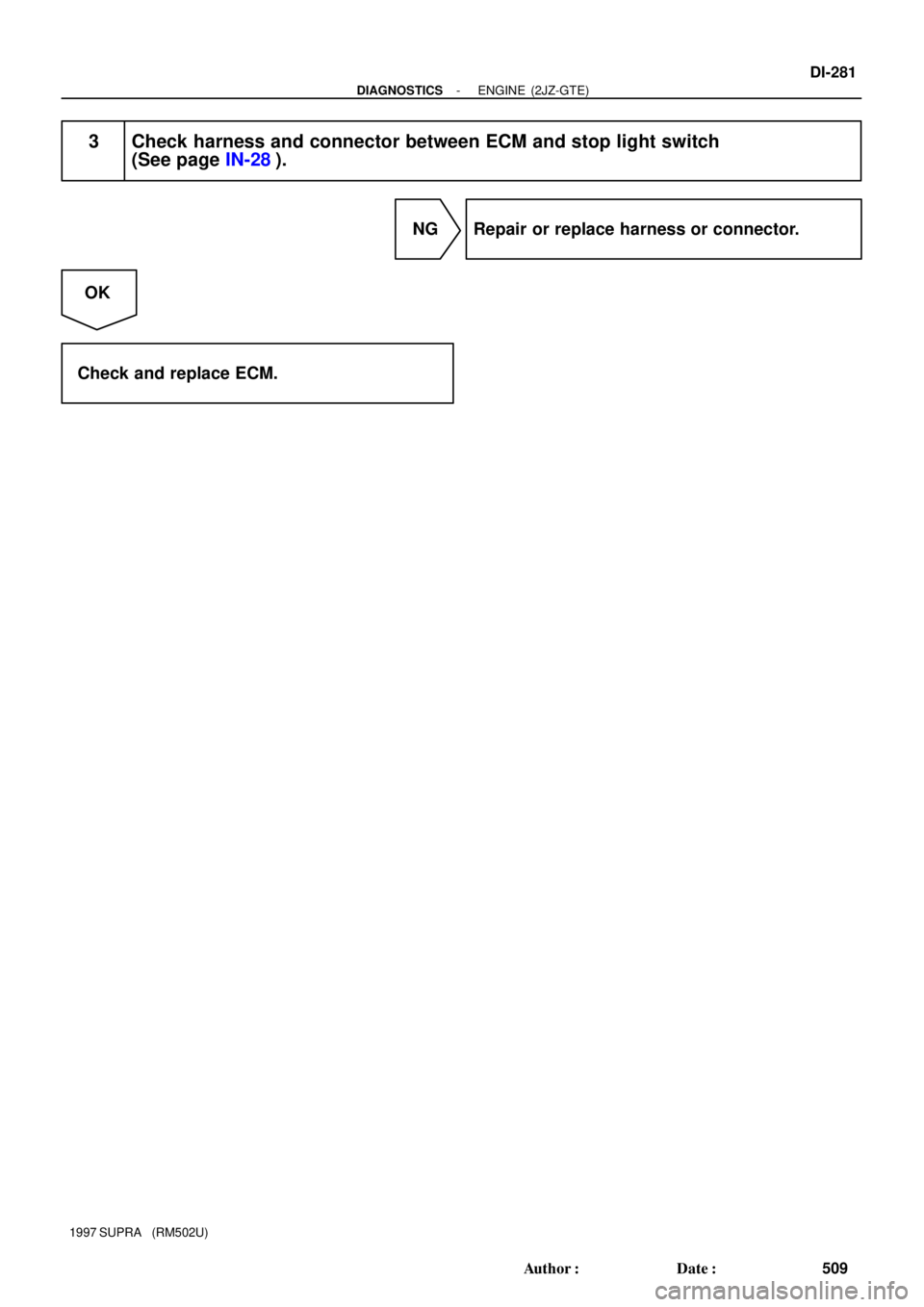
3 Check harness and connector between ECM and stop light switch
(See page IN-28).
NG Repair or replace harness or connector.
OK
Check and replace ECM.
Page 735 of 1807

7276
ON
OFF
0.5 sec.
0.5 sec.1.5 sec.
0.5 sec.0.5 sec.2.5 sec.
4 sec.
Repeat DI-444
- DI")
F00007
E1
Tc
Ts
lei-23-1-A
DLC1
BR3904
0.13 sec.
0.13 sec.
ON
OFF
BR3893
Malfunction Code (Example Code 72, 76)
7276
ON
OFF
0.5 sec.
0.5 sec.1.5 sec.
0.5 sec.0.5 sec.2.5 sec.
4 sec.
Repeat DI-444
- DIAGNOSTICSANTI-LOCK BRAKE SYSTEM
672 Author�: Date�:
1997 SUPRA (RM502U)
2. SPEED SENSOR SIGNAL AND DECELERATION SEN-
SOR
(a) Check the speed sensor signal and deceleration sensor.
(1) Turn the ignition switch OFF
(2) Using SST, connect terminal Ts and E1 of DLC1.
SST 09843-18020
(3) Start the engine.
(4) Check that the ABS warning light blinks.
HINT:
�If the ABS warning light does not blink, inspect the ABS
warning light circuit (See page DI-488).
�If the ABS warning light is always on, inspect and repair,
deceleration sensor.
(5) Drive the vehicle faster than 45 km/h (28 mph) for
several seconds.
(6) Stop the vehicle.
(7) Using SST, connect terminals Tc an E1 of DLC1.
SST 09843-18020
(8) Read the number of blinks of the ABS warning light.
HINT:
�See the list of DTC shown on the next page.
�If every sensor is normal, a normal code is output (A cycle
of 0.25 sec. ON and 0.25 sec. OFF is repeated).
�If 2 or more malfunctions are indicated at the same time,
the lowest numbered code will be displayed 1st.
(9) After doing the check, disconnect terminals Ts and
E1, Tc and E1 of DLC1, and turn ignition switch OFF.
Page 773 of 1807
F03341
R/B No.2J/B No.1Stop Light
SwitchABS ECU
125
Light
Failure
Sensor
Stop LightJ/B
No.11
10IH
IC
A18 A22 *1*2
G-WG-W
G-W1
2 W STOP
210
1B 1I W-LPOWER
22 W
2
2A
ALTR/B No.2
B
Battery
NORMAL ABS (2JZ-GE Engine)
SPORT ABS (2JS-GTE Engine)
*1:
*2:
1
DI-482
- DIAGNOSTICSANTI-LOCK BRAKE SYSTEM
710 Author�: Date�:
1997 SUPRA (RM502U)
DTC 49 Stop Light Switch Circuit
CIRCUIT DESCRIPTION
This stop light switch senses whether the brake pedal is depressed or released, and sends a signal to the
ECU.
DTC No.DTC Detecting ConditionTrouble Area
491.2 - 1.7 V of STP voltage is continued for 0.3 sec. or more.�Open in stop light circuit
WIRING DIAGRAM
INSPECTION PROCEDURE
1 Check operation of stop light.
CHECK:
Check that stop light lights up when brake pedal is depressed and turns off when brake pedal is released.
NG Replace stop light bulb.
OK
DI4VI-01
Page 774 of 1807
F03342F03343F03344
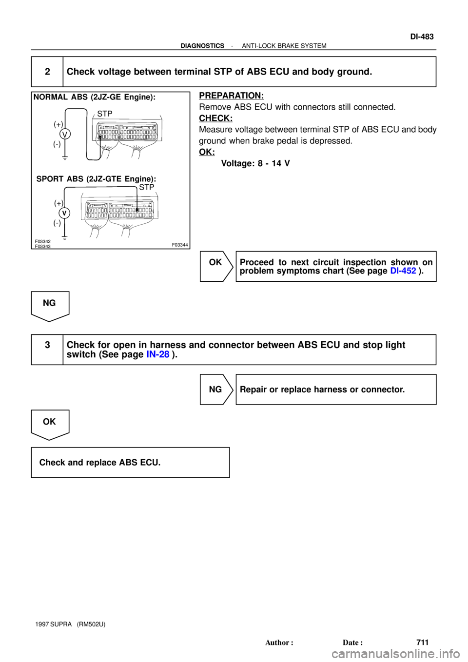
NORMAL ABS (2JZ-GE Engine):
SPORT ABS (2JZ-GTE Engine):V (+)
(-)
(+)
(-)STP
STP
- DIAGNOSTICSANTI-LOCK BRAKE SYSTEM
DI-483
711 Author�: Date�:
1997 SUPRA (RM502U)
2 Check voltage between terminal STP of ABS ECU and body ground.
PREPARATION:
Remove ABS ECU with connectors still connected.
CHECK:
Measure voltage between terminal STP of ABS ECU and body
ground when brake pedal is depressed.
OK:
Voltage: 8 - 14 V
OK Proceed to next circuit inspection shown on
problem symptoms chart (See page DI-452).
NG
3 Check for open in harness and connector between ABS ECU and stop light
switch (See page IN-28).
NG Repair or replace harness or connector.
OK
Check and replace ABS ECU.
Page 777 of 1807
DI-486
- DIAGNOSTICSANTI-LOCK BRAKE SYSTEM
714 Author�: Date�:
1997 SUPRA (RM502U)
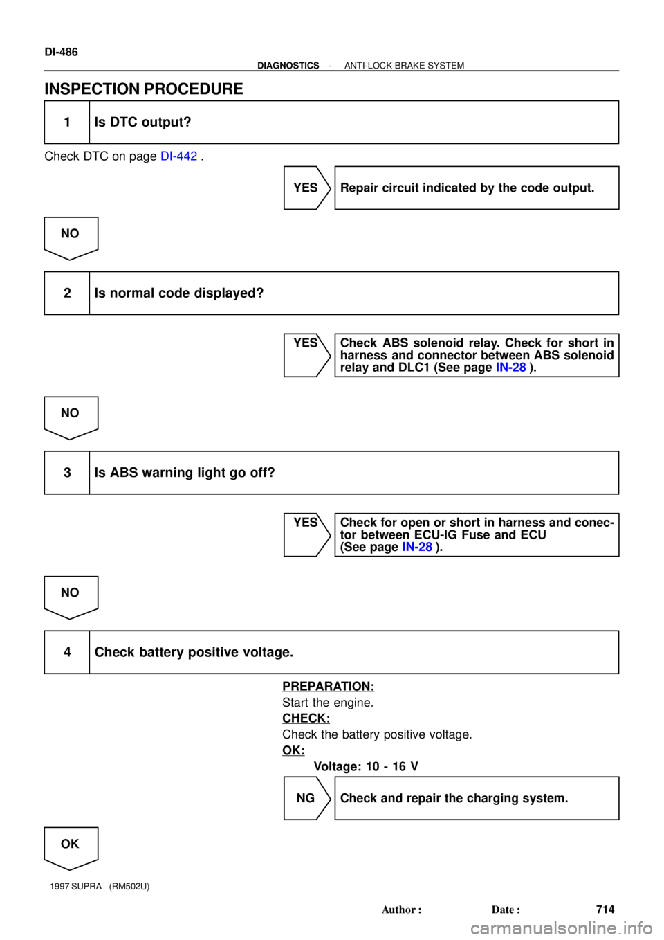
INSPECTION PROCEDURE
1 Is DTC output?
Check DTC on page DI-442.
YES Repair circuit indicated by the code output.
NO
2 Is normal code displayed?
YES Check ABS solenoid relay. Check for short in
harness and connector between ABS solenoid
relay and DLC1 (See page IN-28).
NO
3 Is ABS warning light go off?
YES Check for open or short in harness and conec-
tor between ECU-IG Fuse and ECU
(See page IN-28).
NO
4 Check battery positive voltage.
PREPARATION:
Start the engine.
CHECK:
Check the battery positive voltage.
OK:
Voltage: 10 - 16 V
NG Check and repair the charging system.
OK
Page 780 of 1807

(-) LOCK
- DIAGNOSTICSANTI-LOCK BRAKE SYSTEM
DI-489
717 Author�: Date�:
1997 SUPRA (RM502U)
INSPECT")
F02629F03349F03350
LOCK
Open
ContinuityA8A9
Continuity
F02629F03351F03352
OpenContinuity
A8 A9
(+)
(-) LOCK
- DIAGNOSTICSANTI-LOCK BRAKE SYSTEM
DI-489
717 Author�: Date�:
1997 SUPRA (RM502U)
INSPECTION PROCEDURE
2JZ-GE Engine:
Troubleshooting in accordance with the chart below for each trouble symptom.
ABS warning light does not light upGo to step 1
ABS warning light remains onGo to step 3
1 Check ABS warning light.
See Combination Meter Troubleshooting on page BE-2.
NG Replace bulb or combination meter assembly.
OK
2 Check ABS control (solenoid) relay.
PREPARATION:
Disconnect the connectors from ABS control (solenoid) relay.
CHECK:
Check continuity between each terminal of ABS control (sole-
noid) relay.
OK:
Terminals A9 - 1 and A8 - 3Continuity (Reference value 80 W)
Terminals A9 - 5 and A9 - 6Continuity
Terminals A9 - 2 and A9 - 5Open
CHECK:
(a) Apply battery positive voltage between terminals A9 - 1
and A8 - 3.
(b) Check continuity between each terminal of ABS solenoid
relay.
OK:
Terminals A9 - 5 and A9 - 6Open
Terminals A9 - 2 and A9 - 5Continuity
Page 782 of 1807
F02629F03355
F03356
LOCK
Open
Continuity
Continuity
- DIAGNOSTICSANTI-LOCK BRAKE SYSTEM
DI-491
719 Author�: Date�:
1997 SUPRA (RM502U)
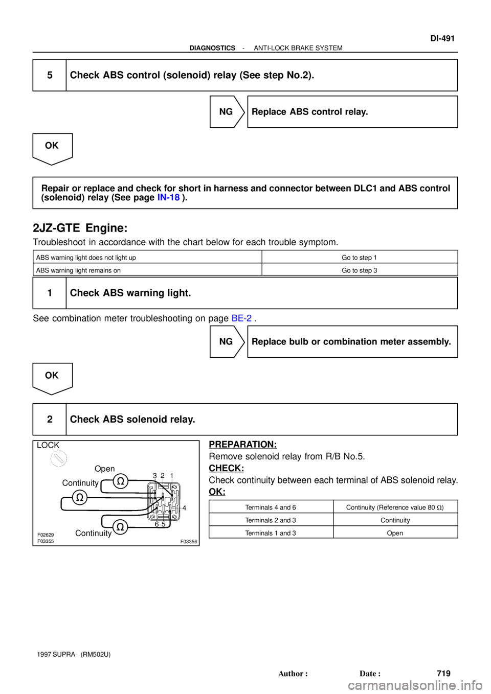
5 Check ABS control (solenoid) relay (See step No.2).
NG Replace ABS control relay.
OK
Repair or replace and check for short in harness and connector between DLC1 and ABS control
(solenoid) relay (See page IN-18).
2JZ-GTE Engine:
Troubleshoot in accordance with the chart below for each trouble symptom.
ABS warning light does not light upGo to step 1
ABS warning light remains onGo to step 3
1 Check ABS warning light.
See combination meter troubleshooting on page BE-2.
NG Replace bulb or combination meter assembly.
OK
2 Check ABS solenoid relay.
PREPARATION:
Remove solenoid relay from R/B No.5.
CHECK:
Check continuity between each terminal of ABS solenoid relay.
OK:
Terminals 4 and 6Continuity (Reference value 80 W)
Terminals 2 and 3Continuity
Terminals 1 and 3Open
Page 785 of 1807
F03361
ABS ECU
12 V
Tc
A20 A1998
*1 *2
R
R
R
IF1
11
P-B
II1 DLC1
R
*121*2P-B R
*1
*2
DLC2
11 Tc E
13
BR
BR BR
ED
IJ1 18BR
Tc E
134
NORMAL ABS (2JZ-GE Engine)
SPORT ABS (2JZ-GTE Engine)
*1:
*2:
S-17-1 Iei-23-1-A
F00041
DLC2
DLC1
E1Tc
E1
Tc
DI-494
- DIAGNOSTICSANTI-LOCK BRAKE SYSTEM
722 Author�: Date�:
1997 SUPRA (RM502U)
Tc Terminal Circuit
CIRCUIT DESCRIPTION
Connecting terminals Tc and E1 of the DLC1 or the DLC1 or the DLC2 causes the ECU to display the DTC
by flashing the ABS warning light.
WIRING DIAGRAM
INSPECTION PROCEDURE
1 Check voltage between terminals Tc and E1 of DLC2 or DLC1.
PREPARATION:
Turn ignition switch ON.
CHECK:
Measure voltage between terminals Tc and E1 of DLC2 or
DLC1.
OK:
Voltage: 10 - 14 V
OK If ABS warning light does not blink even after Tc
and E1 are connected, the ECU may be defec-
tive.
NG
DI4VM-01


SPORT ABS (2JZ-GTE Engine)
*1:
*2:
S-17-1")