Page 1501 of 1807
Z09125
0.65 mm
S00022
Ohmmeter
IDL
E2 Turn
B02446
B02858
0.54 or 0.70 mm
Ohmmeter
E2IDL
P11455
Ohmmeter
A B
A-B-
- SFI (2JZ-GTE)THROTTLE BODY
SF-45
1371 Author�: Date�:
1997 SUPRA (RM502U)
(b) Insert a 0.65 mm (0.026 in.) feeler gauge between the
throttle stop screw and stop lever.
(c) Connect the tester probe of an ohmmeter to the terminals
IDL and E2 of the sensor.
(d) Gradually turn the sensor clockwise until the ohmmeter
deflects, and secure it with the 2 set screws.
(e) Recheck the continuity between terminals IDL and E2.
Clearance between
lever and stop screwContinuity (IDL - E2)
0.54 mm (0.021 in.)Continuity
0.75 mm (0.028 in.)No continuity
(f) Reconnect the vacuum hose to the throttle body.
5. INSPECT SUB-THROTTLE ACTUATOR
Using an ohmmeter, measure the resistance between the ter-
minals (A and A-,to B and B-).
Resistance: 0.82 - 0.98 W at 20°C (68°F)
If the resistance is not as specified, replace the actuator.
Page 1503 of 1807
Z09127
Sub-Throttle
Valve
Closed0.45 mm
S00023
Ohmmeter
E2
IDL
Turn
Z09130
Sub-Throttle
Valve
0.41 or
0.48 mm
Closed
Ohmmeter
E2
IDL
VTA
VC
- SFI (2JZ-GTE)THROTTLE BODY
SF-47
1373 Author�: Date�:
1997 SUPRA (RM502U)
(b) Set the sub-throttle valve to fully closed position.
(c) Insert a 0.45 mm (0.018 in.) feeler gauge, between the
throttle stop screw and throttle valve gear.
(d) Connect the tester probe of an ohmmeter to the terminals
IDL and E2 of the sensor.
(e) Gradually turn the sensor clockwise until the ohmmeter
deflects, and secure it with the 2 set screws.
(f) Recheck the continuity between terminals IDL and E2.
Clearance between
lever and stop screwContinuity (IDL - E2)
0.41 mm (0.016 in.)Continuity
0.48 mm (0.019 in.)No continuity
10. REINSTALL SUB-THROTTLE ACTUATOR
Install the sub-throttle actuator with the 4 screws.
Page 1590 of 1807

SR142-01
W02982
R07283
Matchmarks A
B
R05740
Red Mark
- STEERINGTILT STEERING COLUMN
SR-21
1905 Author�: Date�:
1997 SUPRA (RM502U)
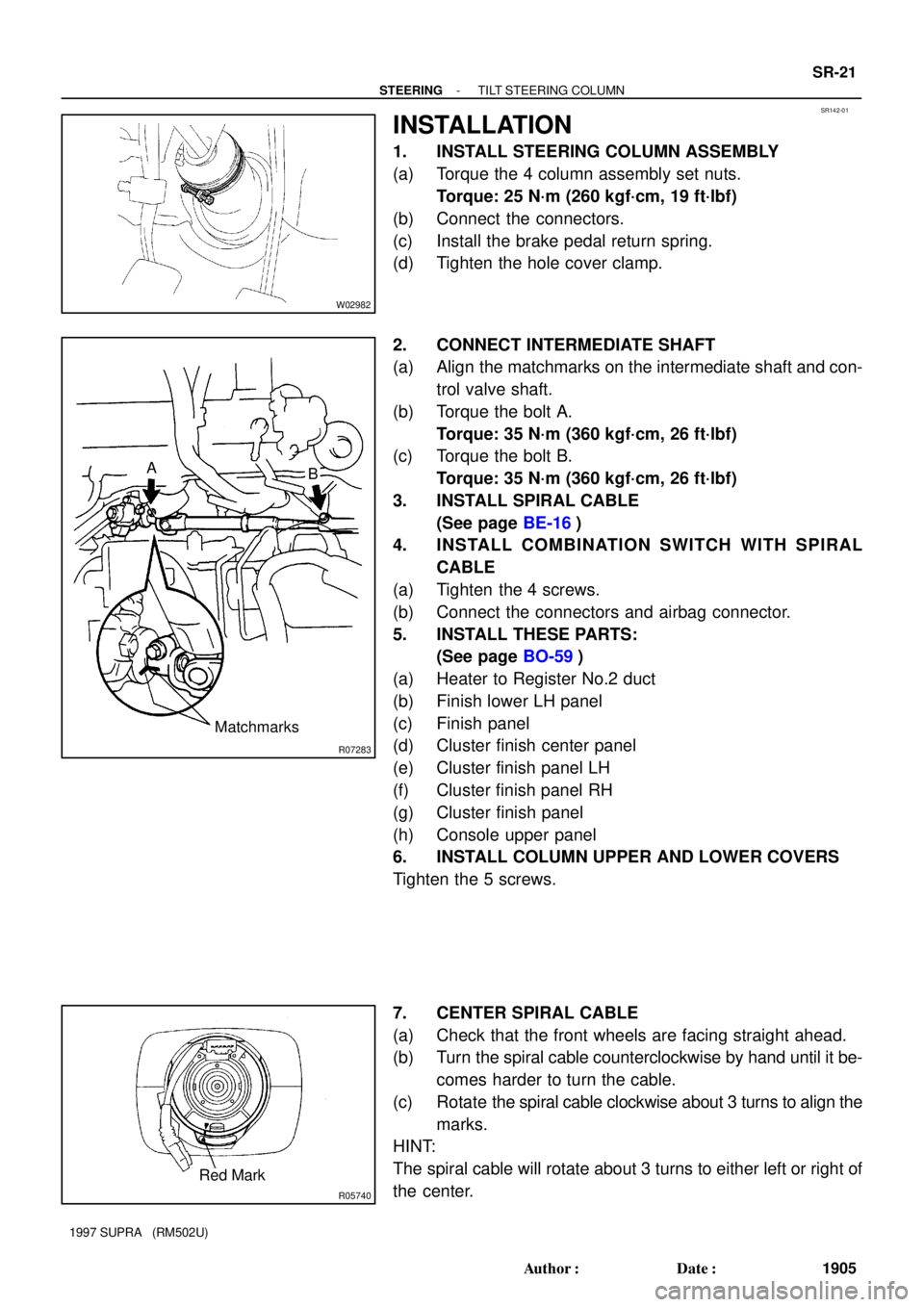
INSTALLATION
1. INSTALL STEERING COLUMN ASSEMBLY
(a) Torque the 4 column assembly set nuts.
Torque: 25 N´m (260 kgf´cm, 19 ft´lbf)
(b) Connect the connectors.
(c) Install the brake pedal return spring.
(d) Tighten the hole cover clamp.
2. CONNECT INTERMEDIATE SHAFT
(a) Align the matchmarks on the intermediate shaft and con-
trol valve shaft.
(b) Torque the bolt A.
Torque: 35 N´m (360 kgf´cm, 26 ft´lbf)
(c) Torque the bolt B.
Torque: 35 N´m (360 kgf´cm, 26 ft´lbf)
3. INSTALL SPIRAL CABLE
(See page BE-16)
4. INSTALL COMBINATION SWITCH WITH SPIRAL
CABLE
(a) Tighten the 4 screws.
(b) Connect the connectors and airbag connector.
5. INSTALL THESE PARTS:
(See page BO-59)
(a) Heater to Register No.2 duct
(b) Finish lower LH panel
(c) Finish panel
(d) Cluster finish center panel
(e) Cluster finish panel LH
(f) Cluster finish panel RH
(g) Cluster finish panel
(h) Console upper panel
6. INSTALL COLUMN UPPER AND LOWER COVERS
Tighten the 5 screws.
7. CENTER SPIRAL CABLE
(a) Check that the front wheels are facing straight ahead.
(b) Turn the spiral cable counterclockwise by hand until it be-
comes harder to turn the cable.
(c) Rotate the spiral cable clockwise about 3 turns to align the
marks.
HINT:
The spiral cable will rotate about 3 turns to either left or right of
the center.
Page 1595 of 1807

SR144-01
R06091
R07429
R07432
SR-26
- STEERINGPOWER STEERING VANE PUMP
1910 Author�: Date�:
1997 SUPRA (RM502U)
REMOVAL
1. REMOVE ENGINE UNDER COVER
Remove the 10 screws.
2. REMOVE BATTERY
(a) Disconnect the 2 terminals.
(b) Remove the bolt, nut and battery clamp.
(c) Remove the battery cover.
(d) Remove the battery and battery carrier.
3. 2JZ-GTE:
REMOVE AIR HOSE No.5
4. REMOVE DRIVE BELT
Loosen the drive belt tension by turning the drive belt tensioner
clockwise, and remove the drive belt.
5. 2JZ-GTE:
DISCONNECT OIL RESERVOIR TO PUMP HOSE
Remove the clip and disconnect the hose.
NOTICE:
Take care not to spill fluid on the A/C compressor rotor.
6. 2JZ-GE:
DISCONNECT RETURN TUBE
NOTICE:
Take care not to spill fluid on the A/C compressor rotor.
7. 2JZ-GTE:
REMOVE VANE PUMP PULLEY
Using SST to stop the pulley rotating, remove the nut.
SST 09960-10010 (09962-01000, 09963-01000)
8. REMOVE PRESSURE FEED TUBE
Using a spanner (24 mm) to hold the pressure port union, re-
move the union bolt and gasket.
9. REMOVE PS VANE PUMP ASSEMBLY
Remove the 2 pump assembly set bolts.
Page 1611 of 1807

SR14C-01
R10072
R07288
A
B
C
BearingSST
R07109
Cutouts
SST
Oil Seal
W00209
Press
SST
Oil Seal
SST
W00210
SST
Bearing SR-42
- STEERINGPOWER STEERING GEAR
1926 Author�: Date�:
1997 SUPRA (RM502U)
INSPECTION
NOTICE:
When using a vise, do not overtighten it.
1. INSPECT STEERING RACK
(a) Using a dial indicator, check the rack for runout and for
teeth wear or damage.
Maximum runout: 0.30mm (0.018 in.)
(b) Check the back surface for wear or damage.
2. IF NECESSARY, REPLACE OIL SEAL AND BEARING
(a) Set SST to the rack housing, as shown.
SST 09612-30012
(b) Turn A clockwise and engage the tips of C on the bearing.
(c) Using a spanner (8 mm), keep A fixed while turning nut B
clockwise, and remove the bearing.
NOTICE:
Be careful not to damage the rack housing.
(d) Using SST, remove the oil seal from the rack housing.
SST 09612-30012
NOTICE:
Be careful not to damage the rack housing.
HINT:
When using SST, apply the tips of SST to the cutouts in the rack
housing.
(e) Coat a new oil seal lip with power steering fluid.
(f) Using SST, press in the oil seal.
SST 09950-60010 (09951-00280, 09951-00390,
09952-06010), 09950-70010 (09951-07100)
NOTICE:
Make sure to install the oil seal facing the correct direction.
(g) Using SST, press in the bearing.
SST 09950-60010 (09951-00460),
09950-70010 (09951-07100)