Page 1310 of 1807
EM0AV-02
P11544
(2)(3)
(1) EM-58
- ENGINE MECHANICAL (2JZ-GTE)ENGINE UNIT
1163 Author�: Date�:
1997 SUPRA (RM502U)
REMOVAL
1. REMOVE HOOD
2. REMOVE RADIATOR ASSEMBLY
(See page CO-22)
3. DRAIN ENGINE OIL
4. DRAIN FUEL FROM FUEL TANK
5. REMOVE NO.1 AIR HOSE
6. DISCONNECT CONTROL CABLES FROM
THROTTLE BODY
Disconnect these cables:
�Accelerator cable
�Cruise control actuator cable
7. REMOVE AIR CLEANER AND MAF METER
ASSEMBLY
(a) Remove the 3 bolts.
(b) Loosen the hose clamp, disconnect the air hose from the
intake air connector.
(c) Disconnect the MAF meter wire from the clamp on the air
cleaner case.
(d) Disconnect the MAF meter connector, and remove the air
cleaner and MAF meter assembly.
8. M/T:
REMOVE DRIVE BELT TENSIONER DAMPER
(See page EM-15)
9. REMOVE DRIVE BELT, FAN, FLUID COUPLING
ASSEMBLY AND WATER PUMP PULLEY
(See page CO-7)
10. REMOVE CHARCOAL CANISTER
11. DISCONNECT HEATER WATER HOSES
12. DISCONNECT BRAKE BOOSTER VACUUM HOSE
13. DISCONNECT EVAP HOSE
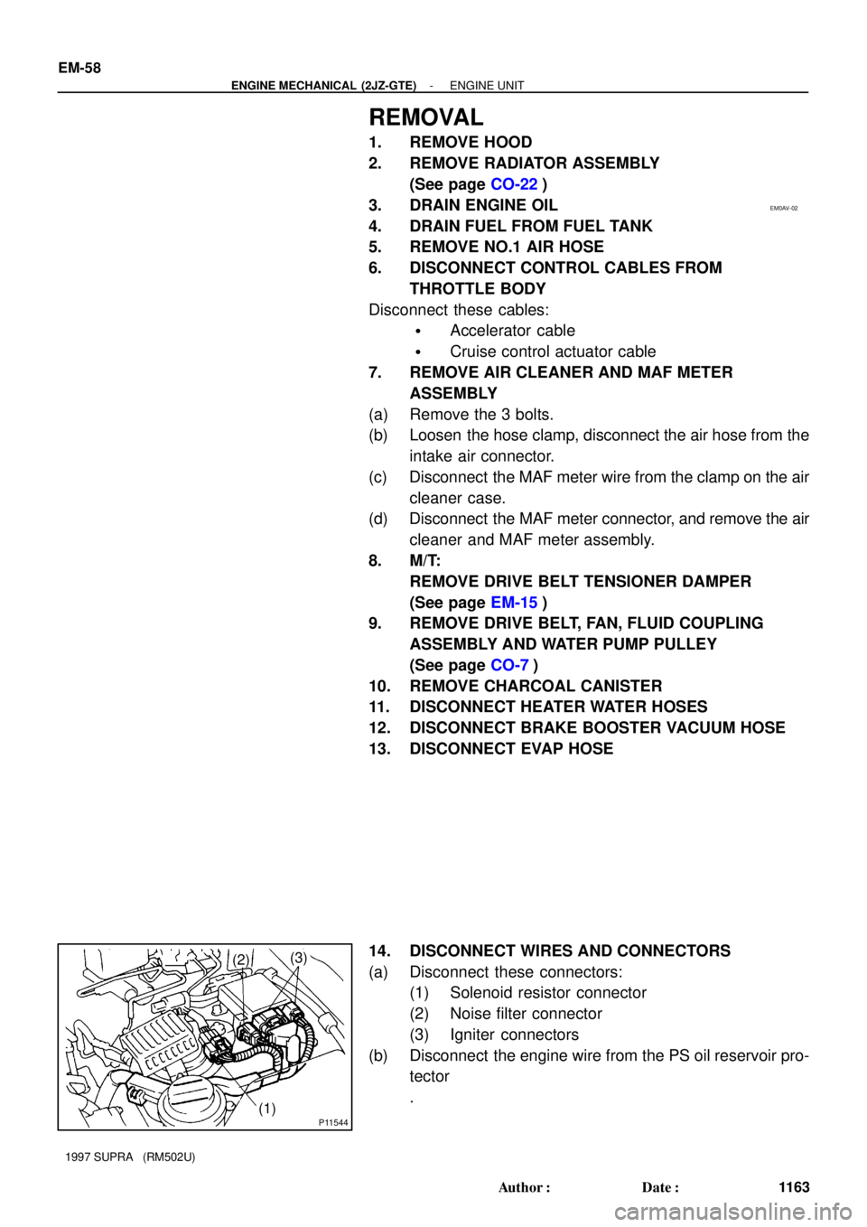
14. DISCONNECT WIRES AND CONNECTORS
(a) Disconnect these connectors:
(1) Solenoid resistor connector
(2) Noise filter connector
(3) Igniter connectors
(b) Disconnect the engine wire from the PS oil reservoir pro-
tector
.
Page 1323 of 1807
EM0AO-02
P02447
P04467
P12207Knock Sensor
Union for Oil Cooler HoseOil Pressure
Switch
SST
- ENGINE MECHANICAL (2JZ-GTE)CYLINDER BLOCK
EM-71
1176 Author�: Date�:
1997 SUPRA (RM502U)
DISASSEMBLY
1. M/T:
REMOVE FLYWHEEL
2. A/T:
REMOVE DRIVE PLATE
3. INSTALL ENGINE TO ENGINE STAND FOR
DISASSEMBLY
4. REMOVE GENERATOR
5. REMOVE TIMING BELT AND PULLEYS
(See page EM-15)
6. REMOVE CYLINDER HEAD (See page EM-29)
7. REMOVE OIL COOLER (See page LU-20)
8. REMOVE NO.2 WATER BYPASS PIPE WITH HOSE
Remove the 2 bolts, 2 nuts, water bypass pipe and gasket.
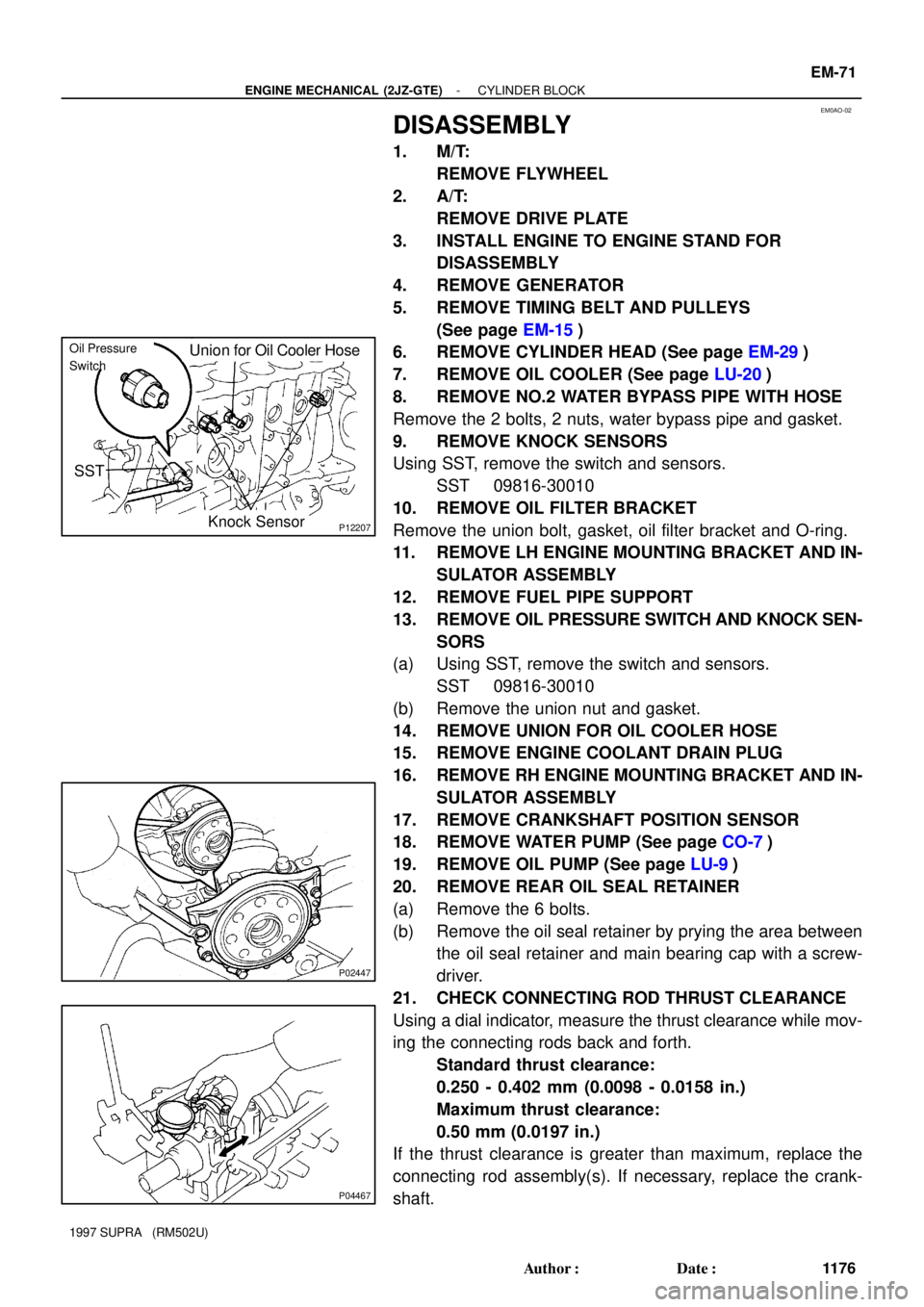
9. REMOVE KNOCK SENSORS
Using SST, remove the switch and sensors.
SST 09816-30010
10. REMOVE OIL FILTER BRACKET
Remove the union bolt, gasket, oil filter bracket and O-ring.
11. REMOVE LH ENGINE MOUNTING BRACKET AND IN-
SULATOR ASSEMBLY
12. REMOVE FUEL PIPE SUPPORT
13. REMOVE OIL PRESSURE SWITCH AND KNOCK SEN-
SORS
(a) Using SST, remove the switch and sensors.
SST 09816-30010
(b) Remove the union nut and gasket.
14. REMOVE UNION FOR OIL COOLER HOSE
15. REMOVE ENGINE COOLANT DRAIN PLUG
16. REMOVE RH ENGINE MOUNTING BRACKET AND IN-
SULATOR ASSEMBLY
17. REMOVE CRANKSHAFT POSITION SENSOR
18. REMOVE WATER PUMP (See page CO-7)
19. REMOVE OIL PUMP (See page LU-9)
20. REMOVE REAR OIL SEAL RETAINER
(a) Remove the 6 bolts.
(b) Remove the oil seal retainer by prying the area between
the oil seal retainer and main bearing cap with a screw-
driver.
21. CHECK CONNECTING ROD THRUST CLEARANCE
Using a dial indicator, measure the thrust clearance while mov-
ing the connecting rods back and forth.
Standard thrust clearance:
0.250 - 0.402 mm (0.0098 - 0.0158 in.)
Maximum thrust clearance:
0.50 mm (0.0197 in.)
If the thrust clearance is greater than maximum, replace the
connecting rod assembly(s). If necessary, replace the crank-
shaft.
Page 1344 of 1807
P02420
90°Painted Mark
90°
P02197
Seal Width
2 - 3 mm
Seal
Packing
P02104
Z16761
Adhesive EM-92
- ENGINE MECHANICAL (2JZ-GTE)CYLINDER BLOCK
1197 Author�: Date�:
1997 SUPRA (RM502U)
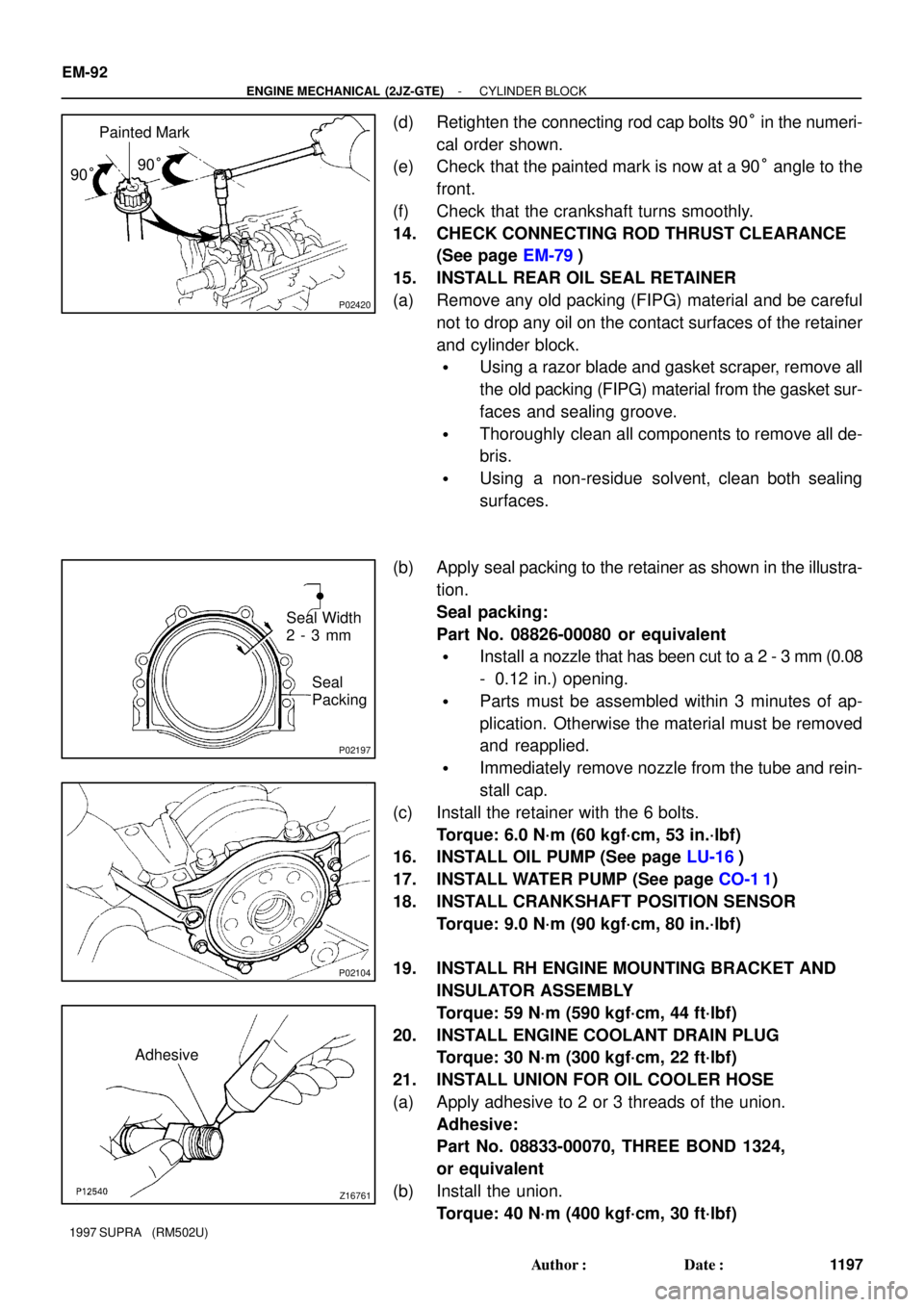
(d) Retighten the connecting rod cap bolts 90° in the numeri-
cal order shown.
(e) Check that the painted mark is now at a 90° angle to the
front.
(f) Check that the crankshaft turns smoothly.
14. CHECK CONNECTING ROD THRUST CLEARANCE
(See page EM-79)
15. INSTALL REAR OIL SEAL RETAINER
(a) Remove any old packing (FIPG) material and be careful
not to drop any oil on the contact surfaces of the retainer
and cylinder block.
�Using a razor blade and gasket scraper, remove all
the old packing (FIPG) material from the gasket sur-
faces and sealing groove.
�Thoroughly clean all components to remove all de-
bris.
�Using a non-residue solvent, clean both sealing
surfaces.
(b) Apply seal packing to the retainer as shown in the illustra-
tion.
Seal packing:
Part No. 08826-00080 or equivalent
�Install a nozzle that has been cut to a 2 - 3 mm (0.08
- 0.12 in.) opening.
�Parts must be assembled within 3 minutes of ap-
plication. Otherwise the material must be removed
and reapplied.
�Immediately remove nozzle from the tube and rein-
stall cap.
(c) Install the retainer with the 6 bolts.
Torque: 6.0 N´m (60 kgf´cm, 53 in.´lbf)
16. INSTALL OIL PUMP (See page LU-16)
17. INSTALL WATER PUMP (See page CO-1 1)
18. INSTALL CRANKSHAFT POSITION SENSOR
Torque: 9.0 N´m (90 kgf´cm, 80 in.´lbf)
19. INSTALL RH ENGINE MOUNTING BRACKET AND
INSULATOR ASSEMBLY
Torque: 59 N´m (590 kgf´cm, 44 ft´lbf)
20. INSTALL ENGINE COOLANT DRAIN PLUG
Torque: 30 N´m (300 kgf´cm, 22 ft´lbf)
21. INSTALL UNION FOR OIL COOLER HOSE
(a) Apply adhesive to 2 or 3 threads of the union.
Adhesive:
Part No. 08833-00070, THREE BOND 1324,
or equivalent
(b) Install the union.
Torque: 40 N´m (400 kgf´cm, 30 ft´lbf)
Page 1386 of 1807
LU04R-01
P11555
P12215
30 mm
Socket
Wrench LU-20
- LUBRICATIONOIL COOLER (2JZ-GTE)
1467 Author�: Date�:
1997 SUPRA (RM502U)
REMOVAL
1. DISCONNECT PS OIL RESERVOIR WITHOUT
DISCONNECTING HOSES
(a) Disconnect the 2 clamps of the engine wire protector from
the bracket.
(b) Remove the 3 bolts and disconnect the reservoir.
2. DRAIN ENGINE COOLANT
3. REMOVE OIL FILTER
(See page LU-4)
4. DISCONNECT WATER BYPASS HOSES FROM OIL
COOLER
5. REMOVE OIL COOLER
(a) Remove the relief valve, plate washer and oil cooler.
(b) Remove the 2 O-rings from the oil cooler.
Page 1499 of 1807
P11327
(4) (3)
(2)
(!) (5)
(6)
P11328
SF0H8-01
P11329
(1)
(2)
(3)
(4)
- SFI (2JZ-GTE)THROTTLE BODY
SF-43
1369 Author�: Date�:
1997 SUPRA (RM502U)
REMOVAL
1. DRAIN ENGINE COOLANT
2. REMOVE THROTTLE BODY
(a) Disconnect the hose, cables and connectors from the
throttle body:
(1) Air hose
(2) Accelerator cable
(3) Cruise control actuator cable
(4) Throttle position sensor connector
(5) Sub-throttle position sensor connector
(6) Sub-throttle actuator connector
(b) Remove the 2 bolts and 2 nuts, and disconnect the
throttle body from the air intake chamber.
Torque: 21 N´m (210 kgf´cm, 15 ft´lbf)
(c) Remove the gasket.
HINT:
Use a new gasket.
(d) Disconnect these hoses from the throttle body, and re-
move the throttle body:
(1) EVAP hose
(2) Water bypass hose (from No.4 water bypass pipe)
(3) Water bypass hose (from cylinder head)
(4) PS air hose
Page 1506 of 1807
SF0HD-01
P11386Connector
P11418(1)(2)
(3)
P12820
Check Valve
Seal
Washer
- SFI (2JZ-GTE)IDLE AIR CONTROL (IAC) VALVE
SF-51
1377 Author�: Date�:
1997 SUPRA (RM502U)
REMOVAL
1. DRAIN ENGINE COOLANT
2. DISCONNECT IAC VALVE CONNECTOR
3. REMOVE IAC VALVE
(a) Remove the 2 bolts, and disconnect the IAC valve from
the air intake chamber.
(b) Remove the gasket
.
(c) Disconnect these hoses from the IAC valve, and remove
the IAC valve:
(1) Air hose
(2) Water bypass hose (from No.2 water bypass pipe)
(3) Water bypass hose (from No.4 water bypass pipe)
(d) Remove the seal washer and check valve.
Page 1677 of 1807
SA0PW-01
R07211
R07210
SST
R00220
SST
R07212
SST SA-60
- SUSPENSION AND AXLEREAR DIFFERENTIAL SIDE GEAR SHAFT OIL SEAL
1750 Author�: Date�:
1997 SUPRA (RM502U)
REPLACEMENT
1. DRAIN HYPOID GEAR OIL
2. REMOVE REAR DRIVE SHAFT (See page SA-51)
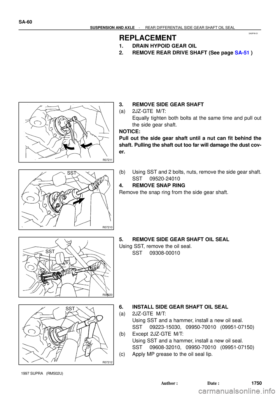
3. REMOVE SIDE GEAR SHAFT
(a) 2JZ-GTE M/T:
Equally tighten both bolts at the same time and pull out
the side gear shaft.
NOTICE:
Pull out the side gear shaft until a nut can fit behind the
shaft. Pulling the shaft out too far will damage the dust cov-
er.
(b) Using SST and 2 bolts, nuts, remove the side gear shaft.
SST 09520-24010
4. REMOVE SNAP RING
Remove the snap ring from the side gear shaft.
5. REMOVE SIDE GEAR SHAFT OIL SEAL
Using SST, remove the oil seal.
SST 09308-00010
6. INSTALL SIDE GEAR SHAFT OIL SEAL
(a) 2JZ-GTE M/T:
Using SST and a hammer, install a new oil seal.
SST 09223-15030, 09950-70010 (09951-07150)
(b) Except 2JZ-GTE M/T:
Using SST and a hammer, install a new oil seal.
SST 09608-32010, 09950-70010 (09951-07150)
(c) Apply MP grease to the oil seal lip.
Page 1682 of 1807
SA0PY-02
R06615
Matchmarks
R06904
R06905
- SUSPENSION AND AXLEREAR DIFFERENTIAL CARRIER
SA-65
1755 Author�: Date�:
1997 SUPRA (RM502U)
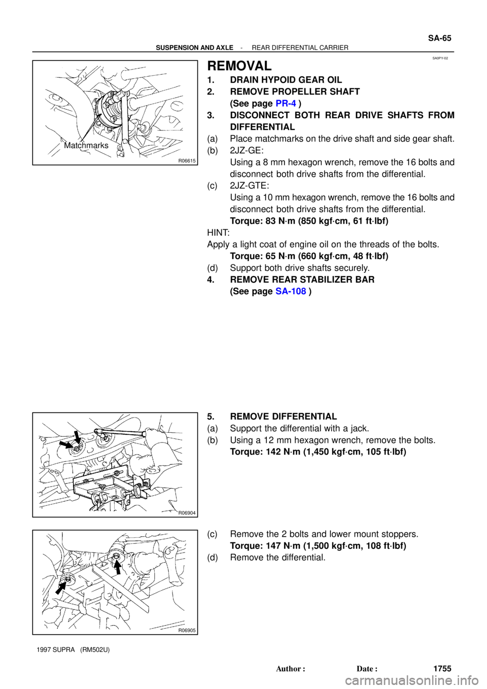
REMOVAL
1. DRAIN HYPOID GEAR OIL
2. REMOVE PROPELLER SHAFT
(See page PR-4)
3. DISCONNECT BOTH REAR DRIVE SHAFTS FROM
DIFFERENTIAL
(a) Place matchmarks on the drive shaft and side gear shaft.
(b) 2JZ-GE:
Using a 8 mm hexagon wrench, remove the 16 bolts and
disconnect both drive shafts from the differential.
(c) 2JZ-GTE:
Using a 10 mm hexagon wrench, remove the 16 bolts and
disconnect both drive shafts from the differential.
Torque: 83 N´m (850 kgf´cm, 61 ft´lbf)
HINT:
Apply a light coat of engine oil on the threads of the bolts.
Torque: 65 N´m (660 kgf´cm, 48 ft´lbf)
(d) Support both drive shafts securely.
4. REMOVE REAR STABILIZER BAR
(See page SA-108)
5. REMOVE DIFFERENTIAL
(a) Support the differential with a jack.
(b) Using a 12 mm hexagon wrench, remove the bolts.
Torque: 142 N´m (1,450 kgf´cm, 105 ft´lbf)
(c) Remove the 2 bolts and lower mount stoppers.
Torque: 147 N´m (1,500 kgf´cm, 108 ft´lbf)
(d) Remove the differential.