Page 917 of 1807
*1
HEAD
(LH-L WR)*2HEAD R/B No.2
FL MAIN
Light Control
Switch
R/B No.2
HEAD
(RH)*1
HEAD
(RH-L WR)*2R-")
I02543
Theft Deterrent and
Door Lock ECU
*1: USA Models
*2: CANADA Models BatteryR/B No.2
HEAD
(LH)*1
HEAD
(LH-L WR)*2HEAD R/B No.2
FL MAIN
Light Control
Switch
R/B No.2
HEAD
(RH)*1
HEAD
(RH-L WR)*2R-Y R-Y R-Y R-Y
R-G R-B
W-B
W-B BRR 2
2
2
22
22
2
11 1 1
4
23
10 16 13
IB2
IF2 2A
EA Headlight Relay
T13
DI-626
- DIAGNOSTICSTHEFT DETERRENT SYSTEM
854 Author�: Date�:
1997 SUPRA (RM502U)
Headlight Control Relay Circuit
CIRCUIT DESCRIPTION
When the theft deterrent system is activated, it causes the Tr in the ECU to switch on and off at approximately
0.2 sec. intervals. This switches the headlight control relay on and off, thus flashing the headlights (See the
wiring diagram below).
In this condition, if any of the following operations is done, the Tr in the ECU goes off and the headlight control
relay switches off, thus stopping the headlights flashing:
(1) The front LH or RH door is unlocked with a key.
(2) The ignition switch is turned to the ACC or ON position.
(3) Approximately 1 minute elapses.
WIRING DIAGRAM
DI4X5-01
Page 918 of 1807
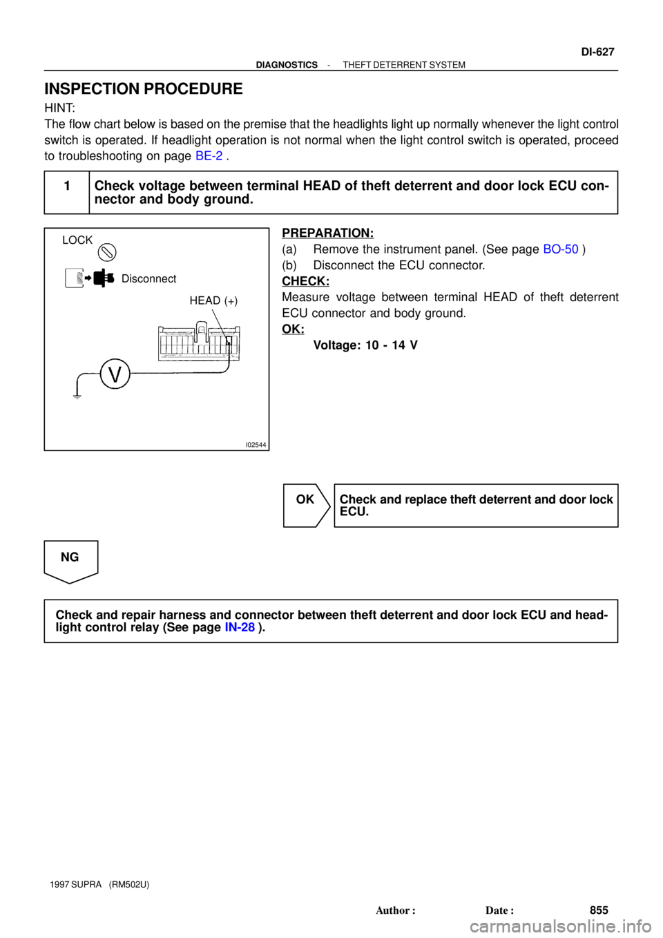
I02544
LOCK
Disconnect
HEAD (+)
- DIAGNOSTICSTHEFT DETERRENT SYSTEM
DI-627
855 Author�: Date�:
1997 SUPRA (RM502U)
INSPECTION PROCEDURE
HINT:
The flow chart below is based on the premise that the headlights light up normally whenever the light control
switch is operated. If headlight operation is not normal when the light control switch is operated, proceed
to troubleshooting on page BE-2.
1 Check voltage between terminal HEAD of theft deterrent and door lock ECU con-
nector and body ground.
PREPARATION:
(a) Remove the instrument panel. (See page BO-50)
(b) Disconnect the ECU connector.
CHECK:
Measure voltage between terminal HEAD of theft deterrent
ECU connector and body ground.
OK:
Voltage: 10 - 14 V
OK Check and replace theft deterrent and door lock
ECU.
NG
Check and repair harness and connector between theft deterrent and door lock ECU and head-
light control relay (See page IN-28).
Page 919 of 1807

I02545
I02545
Theft Deterrent and
Door Lock ECUT13
IF2
2 2
2A22 J/B No.1
1B 1K
1C
LG LGG-W G-W
G-WTAIL 11
16
3 5TAIL 1 W-L
W-B
Ta i l
Light
W-B
W-B
1
193
B
Battery
Light
Failure
Sensor
Light Control Switch15
23
G
Taillight Control Relay
B1
BJ
ALT
POWER
W
1
5
5 2 DI-628
- DIAGNOSTICSTHEFT DETERRENT SYSTEM
856 Author�: Date�:
1997 SUPRA (RM502U)
Taillight Control Relay Circuit
CIRCUIT DESCRIPTION
When the theft deterrent system is activated, it causes the Tr in the ECU to switch on and off at approximately
0.2 sec. intervals. This switches the taillight control relay on and off, thus the taillights flash (See the wiring
diagram below).
In this condition, if any of the following operations is done, the Tr in the ECU goes off and the taillight control
relay switches off, thus stopping the taillights flashing:
(1) The front LH or RH door is unlocked with a key.
(2) The ignition switch is turned to the ACC or ON position.
(3) Approximately 1 minute elapses.
WIRING DIAGRAM
DI4X6-01
Page 920 of 1807
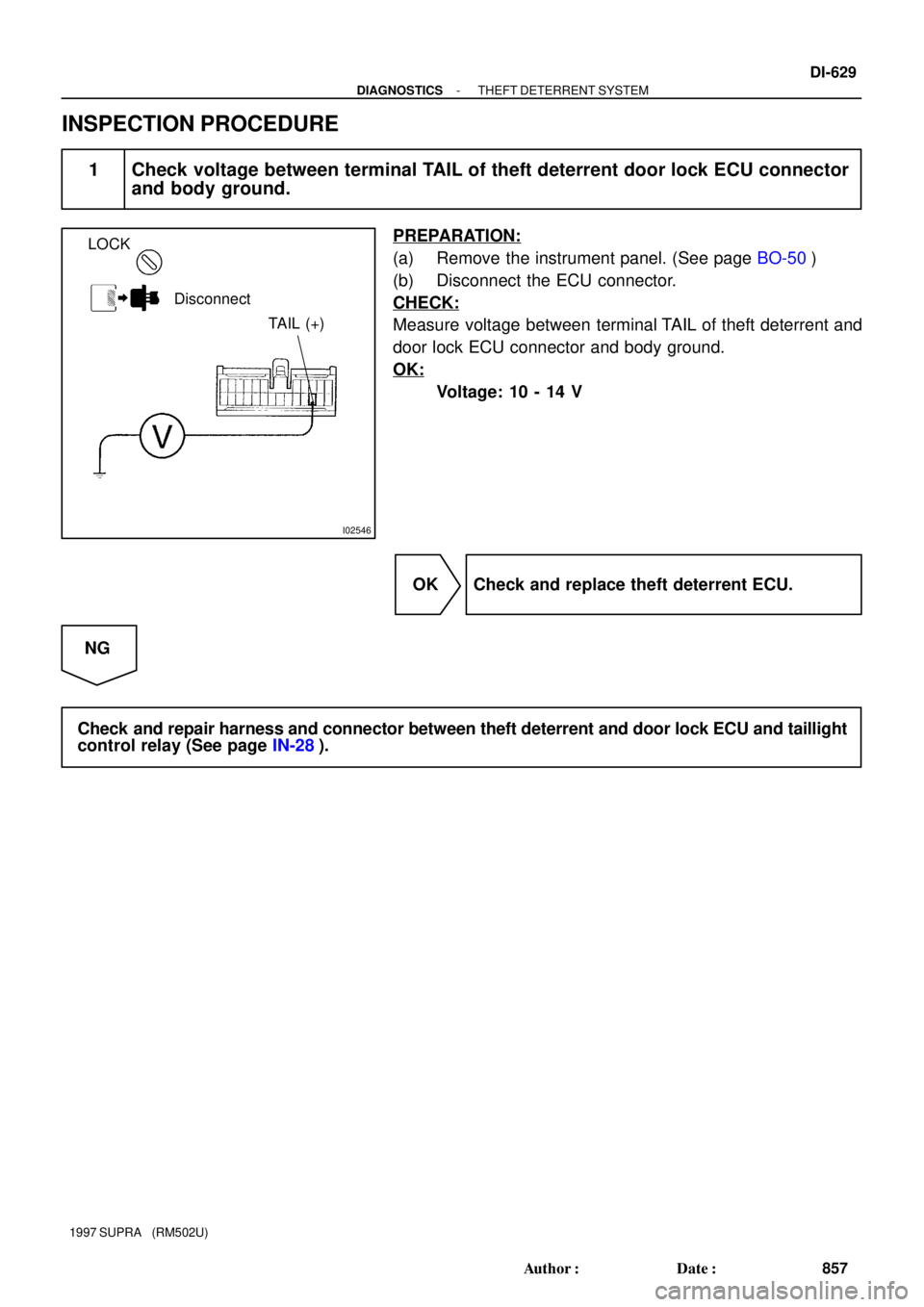
I02546
LOCK
Disconnect
TAIL (+)
- DIAGNOSTICSTHEFT DETERRENT SYSTEM
DI-629
857 Author�: Date�:
1997 SUPRA (RM502U)
INSPECTION PROCEDURE
1 Check voltage between terminal TAIL of theft deterrent door lock ECU connector
and body ground.
PREPARATION:
(a) Remove the instrument panel. (See page BO-50)
(b) Disconnect the ECU connector.
CHECK:
Measure voltage between terminal TAIL of theft deterrent and
door lock ECU connector and body ground.
OK:
Voltage: 10 - 14 V
OK Check and replace theft deterrent ECU.
NG
Check and repair harness and connector between theft deterrent and door lock ECU and taillight
control relay (See page IN-28).
Page 936 of 1807
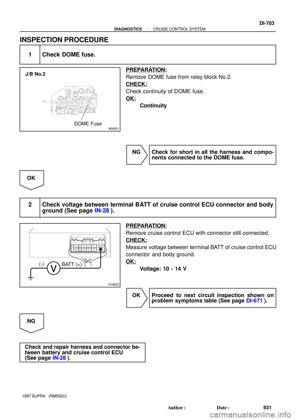
N09001
Relay Block No.2
DOME Fuse
- DIAGNOSTICSTHEFT DETERRENT SYSTEM
DI-645
873 Author�: Date�:
1997 SUPRA (RM502U)
INSPECTION PROCEDURE
1 Check DOME fuse.
PREPARATION:
Remove DOME fuse from R/B No.2.
CHECK:
Check continuity of DOME fuse.
OK:
Continuity
NG Check for short in all the harness and compo-
nents connected to the DOME fuse
(See attached wiring diagram).
OK
Page 939 of 1807
N09001
Relay Block No.2
POWER M-Fuse
DI-648
- DIAGNOSTICSTHEFT DETERRENT SYSTEM
876 Author�: Date�:
1997 SUPRA (RM502U)
INSPECTION PROCEDURE
1 Check POWER M-fuse.
PREPARATION:
Remove POWER M fuse from R/B No.2.
CHECK:
Check continuity of POWER M-fuse.
OK:
Continuity
NG Check for short in all the harness and compo-
nents connected to the DOOR fusible link
(See attached wiring diagram). *
1
OK
Page 994 of 1807
N09001
J/B No.2
DOME Fuse
N19843
(-)
BATT (+)
- DIAGNOSTICSCRUISE CONTROL SYSTEM
DI-703
931 Author�: Date�:
1997 SUPRA (RM502U)
INSPECTION PROCEDURE
1 Check DOME fuse.
PREPARATION:
Remove DOME fuse from relay block No.2.
CHECK:
Check continuity of DOME fuse.
OK:
Continuity
NG Check for short in all the harness and compo-
nents connected to the DOME fuse.
OK
2 Check voltage between terminal BATT of cruise control ECU connector and body
ground (See page IN-28).
PREPARATION:
Remove cruise control ECU with connector still connected.
CHECK:
Measure voltage between terminal BATT of cruise control ECU
connector and body ground.
OK:
Voltage: 10 - 14 V
OK Proceed to next circuit inspection shown on
problem symptoms table (See page DI-671).
NG
Check and repair harness and connector be-
tween battery and cruise control ECU
(See page IN-28).
Page 1001 of 1807
 EL")
A INTRODUCTION
2
This manual consists of the following 11 sections:
A
B
C
D
E
F
G
H
I
J
K
No.
GROUND POINTS
OVERALL
ELECTRICAL
WIRING DIAGRAM SYSTEM CIRCUITSINDEX
POWER SOURCE
(Current Flow Chart) ELECTRICAL
WIRING ROUTING RELAY LOCATIONS GLOSSARY OF
TERMS AND
SYMBOLS ABBREVIATIONS TROUBLE-
SHOOTING HOW TO USE
THIS MANUAL INTRODUCTION INDEX
Section Description
Index of the contents of this manual.
Brief explanation of each section.
Instructions on how to use this manual.
Describes the basic inspection procedures for electrical circuits.
Defines the abbreviations used in this manual.
Defines the symbols and functions of major parts.
Shows position of the Electronic Control Unit, Relays, Relay Block, etc.
This section is closely related to the system circuit.
Describes position of Parts Connectors, Splice points, Ground points, etc.
This section is closely related to the system circuit.
Describes power distribution from the power supply to various electrical
loads.
Index of the system circuits.
Electrical circuits of each system are shown from the power supply through
ground points. Wiring connections and their positions are shown and
classified by code according to the connection method. (Refer to the
section, How to use this manualº).
The System Outlineº and Service Hintsº useful for troubleshooting are
also contained in this section.
Shows ground positions of all the parts described in this manual.
Provides circuit diagrams showing the circuit connections.