Page 2882 of 3342
4. Schematic
B4M1227A
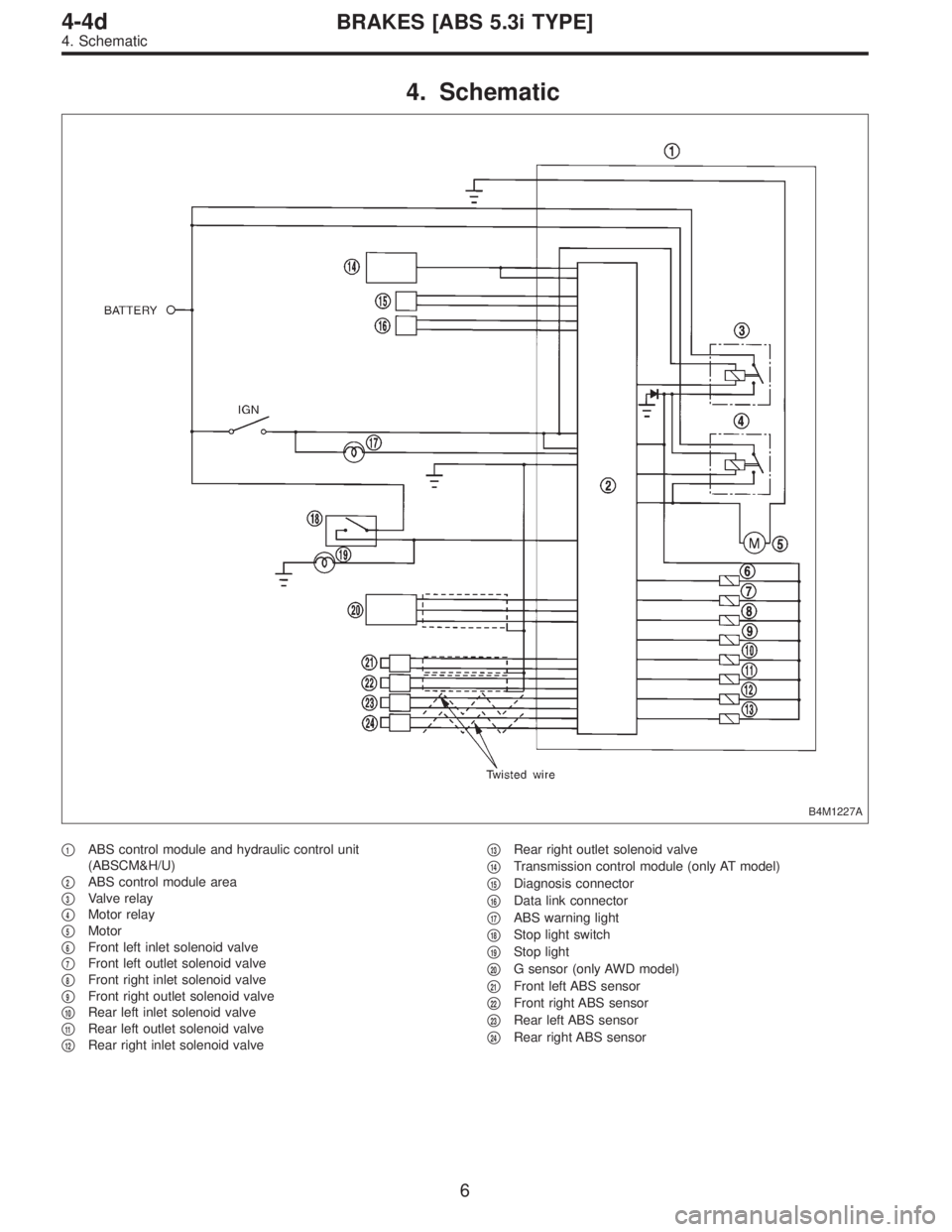
�1ABS control module and hydraulic control unit
(ABSCM&H/U)
�
2ABS control module area
�
3Valve relay
�
4Motor relay
�
5Motor
�
6Front left inlet solenoid valve
�
7Front left outlet solenoid valve
�
8Front right inlet solenoid valve
�
9Front right outlet solenoid valve
�
10Rear left inlet solenoid valve
�
11Rear left outlet solenoid valve
�
12Rear right inlet solenoid valve�
13Rear right outlet solenoid valve
�
14Transmission control module (only AT model)
�
15Diagnosis connector
�
16Data link connector
�
17ABS warning light
�
18Stop light switch
�
19Stop light
�
20G sensor (only AWD model)
�
21Front left ABS sensor
�
22Front right ABS sensor
�
23Rear left ABS sensor
�
24Rear right ABS sensor
6
4-4dBRAKES [ABS 5.3i TYPE]
4. Schematic
Page 2883 of 3342
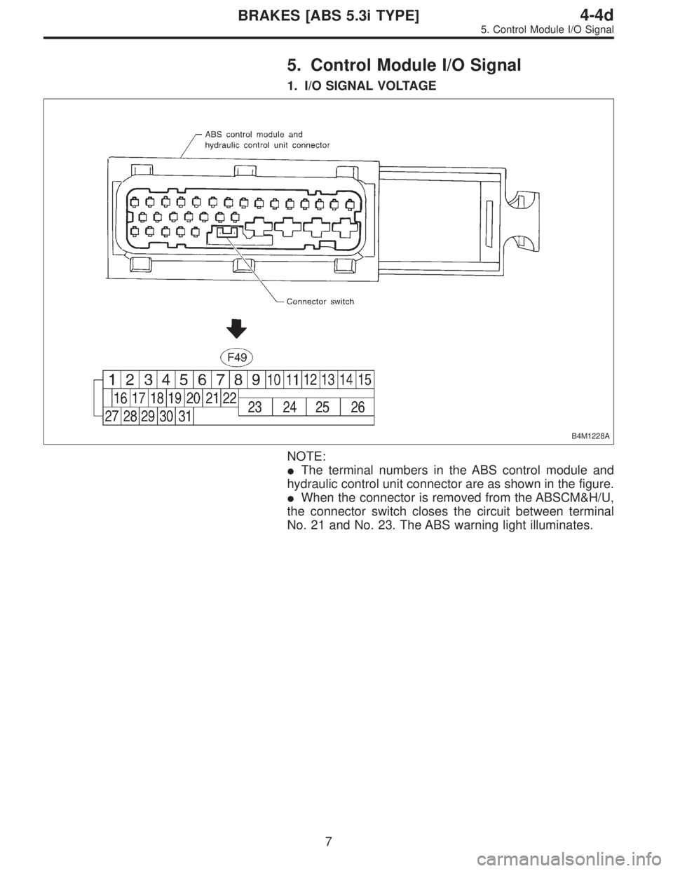
5. Control Module I/O Signal
1. I/O SIGNAL VOLTAGE
B4M1228A
NOTE:
�The terminal numbers in the ABS control module and
hydraulic control unit connector are as shown in the figure.
�When the connector is removed from the ABSCM&H/U,
the connector switch closes the circuit between terminal
No. 21 and No. 23. The ABS warning light illuminates.
7
4-4dBRAKES [ABS 5.3i TYPE]
5. Control Module I/O Signal
Page 2884 of 3342
—(�)Input/Output signal
Measured value and measuring conditions
ABS
sensor*2
(Wheel
speed
sensor)Front left wheel 9—10
0.12 — 1 V
(When it is 20 Hz.) Front right wheel 11")
ContentsTerminal No.
(+)—(�)Input/Output signal
Measured value and measuring conditions
ABS
sensor*2
(Wheel
speed
sensor)Front left wheel 9—10
0.12 — 1 V
(When it is 20 Hz.) Front right wheel 11—12
Rear left wheel 7—8
Rear right wheel 14—15
Valve relay power supply 24—23 10 — 15 V when ignition switch is ON.
Motor relay power supply 25—23 10 — 15 V when ignition switch is ON.
G sensor*2
(AWD
model only)power supply 30—28 4.75 — 5.25 V
ground 28 —
output 6—28 2.3±0.2 V when vehicle is in horizontal position.
Stop light switch*1 2—23Less than 1.5 V when the stop light is OFF and, 10 — 15 V
when the stop light is ON.
ABS warning light*2 21—23Less than 1.5 V during 1.5 seconds when ignition switch is
ON, and 10 — 15 V after 1.5 seconds.
AT ABS signal*2
(AT model only)31—23Less than 1.5 V when the ABS control does not operate still
and more than 5.5 V when ABS operates.
ABS operation signal monitor*2 3—23Less than 1.5 V when the ABS control does not operate still
and more than 5.5 V when ABS operates.
Select
monitor*2Data is received. 20—23 Less than 1.5 V when no data is received.
Data is sent. 5—23 4.75 — 5.25 V when no data is sent.
ABS
diagnosis
connector*2Terminal No. 3 29—23 10 — 15 V when ignition switch is ON.
Terminal No. 6 4—23 10 — 15 V when ignition switch is ON.
Power supply*1 1—23 10 — 15 V when ignition switch is ON.
Grounding line 23 —
Grounding line 26 —
*1: Measure the I/O signal voltage after removing the connector from the ABSCM&H/U terminal.
*2: Measure the I/O signal voltage at connector (F2) or (F1).
8
4-4dBRAKES [ABS 5.3i TYPE]
5. Control Module I/O Signal
Page 2885 of 3342
2. I/O SIGNAL DIAGRAM
B4M1229A
9
4-4dBRAKES [ABS 5.3i TYPE]
5. Control Module I/O Signal
Page 2886 of 3342
6. Diagnostics Chart for On-board
Diagnosis System
A: BASIC DIAGNOSTICS PROCEDURE
B4M1051A
CAUTION:
Remove foreign matter (dust, water, etc.) from the
ABSCM&H/U connector during removal and installa-
tion.
NOTE:
�To check harness for broken wires or short circuits,
shake it while holding it or the connector.
10
4-4dBRAKES [ABS 5.3i TYPE]
6. Diagnostics Chart for On-board Diagnosis System
Page 2887 of 3342

�When ABS warning light illuminates, read and record
trouble code indicated by ABS warning light.
B: CHECK LIST FOR INTERVIEW
Check the following items about the vehicle’s state.
1. THE STATE OF THE ABS WARNING LIGHT
ABS warning light
comes on.�Always
�Sometimes
�Only once
�Does not come on
�When /how long does it come on?:
Ignition key position�LOCK
�ACC
�ON (before starting engine)
�START
�On after starting (Engine is running)
�On after starting (Engine is stop)
Timing�Immediately after ignition is ON.
�Immediately after ignition starts.
�When advancing km/h to km/h
MPH to MPH
�While traveling at a constant speed km/h MPH
�When decelerating km/h to km/h
MPH to MPH
�When turning to right Steering angle : deg
Steering time : sec
�When turning to left Steering angle : deg
Steering time : sec
�When moving other electrical parts
�Parts name :
�Operating condition :
2. SYMPTOMS
ABS operating
condition�Performs no work.
�Operates only when abruptly applying brakes. Vehicle speed : km/h
MPH
�How to step on brake pedal :
a) Operating time :sec
b) Operating noise :�Produce /�Does not produce
�What kind of noise?�Knock
�Gong gong
�Bong
�Buzz
�Gong gong buzz
�Others :
c) Reaction force of brake pedal
�Stick
�Press down once with a clunk
�Press and released
�Others :
11
4-4dBRAKES [ABS 5.3i TYPE]
6. Diagnostics Chart for On-board Diagnosis System
Page 2888 of 3342
 Directional stability cannot be obtained or steering arm refuses to work when applying brakes :
�Ye s /�No
�When :�Vehicle turns to right
�Vehicle turns to left
�Spins
�Others :")
Behavior of vehicle a) Directional stability cannot be obtained or steering arm refuses to work when applying brakes :
�Ye s /�No
�When :�Vehicle turns to right
�Vehicle turns to left
�Spins
�Others :
b) Directional stability cannot be obtained or steering arm refuses to work when accelerating :
�Ye s /�No
�When :�Vehicle turns to right
�Vehicle turns to left
�Spins
�Others :
c) Brakes are out of order :�Ye s /�No
�What :�Braking distance is long
�Brakes lock or drag
�Pedal stroke is long
�Pedal sticks
�Others :
d) Poor acceleration :�Ye s /�No
�What :�Fails to accelerate
�Engine stalls
�Others :
e) Occurrence of vibration :�Ye s /�No
�Where
�What kind :
f) Occurrence of abnormal noise :�Ye s /�No
�Where
�What kind :
g) Occurrence of other phenomena :�Ye s /�No
�What kind :
3. CONDITIONS UNDER WHICH TROUBLE OCCURS
Environment a) Weather�Fine
�Cloudy
�Rainy
�Snowy
�Various/Others :
b) Ambient temperatureF(°C)
c) Road�Urban area
�Suburbs
�Highway
�General road
�Ascending slope
�Descending slope
�Paved road
�Gravel road
�Muddy road
�Sandy place
�Others :
d) Road surface�Dry
�Wet
�New-fallen snow
�Compressed snow
�Frozen slope
�Others :
12
4-4dBRAKES [ABS 5.3i TYPE]
6. Diagnostics Chart for On-board Diagnosis System
Page 2889 of 3342
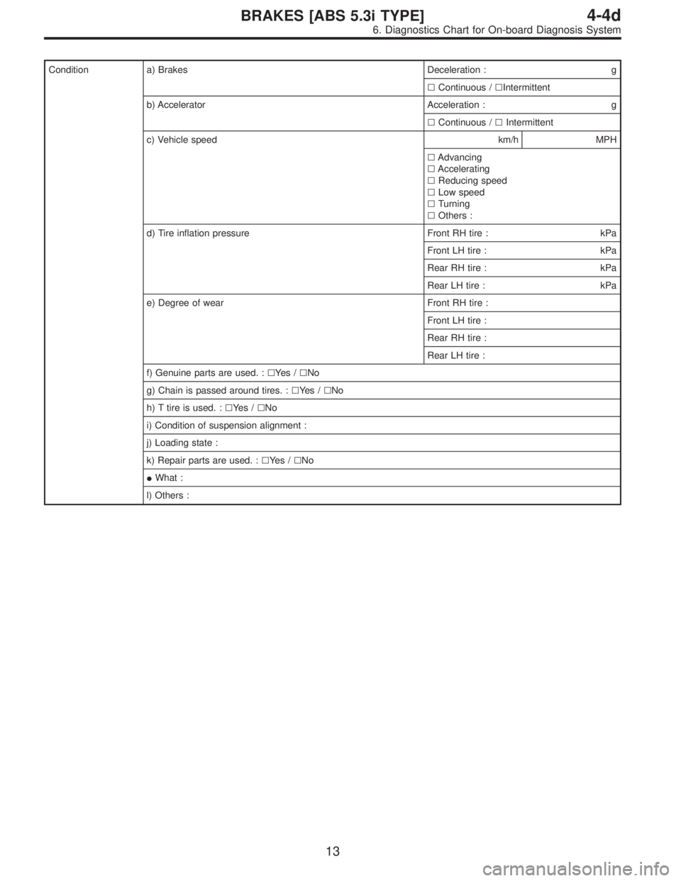
Condition a) Brakes Deceleration : g
�Continuous /�Intermittent
b) Accelerator Acceleration : g
�Continuous /�Intermittent
c) Vehicle speed km/h MPH
�Advancing
�Accelerating
�Reducing speed
�Low speed
�Turning
�Others :
d) Tire inflation pressure Front RH tire : kPa
Front LH tire : kPa
Rear RH tire : kPa
Rear LH tire : kPa
e) Degree of wear Front RH tire :
Front LH tire :
Rear RH tire :
Rear LH tire :
f) Genuine parts are used. :�Ye s /�No
g) Chain is passed around tires. :�Ye s /�No
h) T tire is used. :�Ye s /�No
i) Condition of suspension alignment :
j) Loading state :
k) Repair parts are used. :�Ye s /�No
�What :
l) Others :
13
4-4dBRAKES [ABS 5.3i TYPE]
6. Diagnostics Chart for On-board Diagnosis System
![SUBARU LEGACY 1997 Service Repair Manual 2. I/O SIGNAL DIAGRAM
B4M1229A
9
4-4dBRAKES [ABS 5.3i TYPE]
5. Control Module I/O Signal](/manual-img/17/57434/w960_57434-2884.png "SUBARU LEGACY 1997 Service Repair Manual 2. I/O SIGNAL DIAGRAM
B4M1229A
9
4-4dBRAKES [ABS 5.3i TYPE]
5. Control Module I/O Signal")
 from the
ABSCM&H/U connector during removal and installa-")