Page 2850 of 3342
10AF6
CHECK ABSCM.
1) Connect all connectors.
2) Erase the memory.
3) Perform inspection mode.
4) Read out the trouble code.
: Is the same trouble code as in the current
diagnosis still being output?
: Replace ABSCM.
: Go to next.
: Are other trouble codes being output?
: Proceed with the diagnosis corresponding to the
trouble code.
: A temporary poor contact.
245
4-4cBRAKES [ABS 5.3 TYPE]
10. Diagnostics Chart with Select Monitor
Page 2851 of 3342
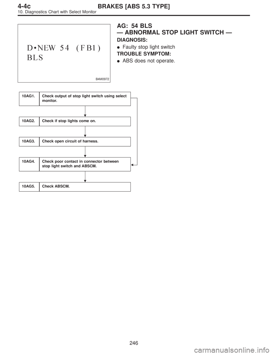
B4M0972
AG: 54 BLS
—ABNORMAL STOP LIGHT SWITCH—
DIAGNOSIS:
�Faulty stop light switch
TROUBLE SYMPTOM:
�ABS does not operate.
10AG1.Check output of stop light switch using select
monitor.
�
10AG2.Check if stop lights come on.
10AG3.Check open circuit of harness.
10AG4.Check poor contact in connector between
stop light switch and ABSCM.
10AG5.Check ABSCM.
�
�
�
�
246
4-4cBRAKES [ABS 5.3 TYPE]
10. Diagnostics Chart with Select Monitor
Page 2852 of 3342
WIRING DIAGRAM:
B4M1041
247
4-4cBRAKES [ABS 5.3 TYPE]
10. Diagnostics Chart with Select Monitor
Page 2853 of 3342
 Press
F,
0and
9on the select monitor.
2) Depress the brake pedal.
3) Read the stop light switch output on the select monitor
dis")
B4M0973
10AG1CHECK OUTPUT OF STOP LIGHT
SWITCH USING SELECT MONITOR.
1) Press
F,
0and
9on the select monitor.
2) Depress the brake pedal.
3) Read the stop light switch output on the select monitor
display.
: Is the reading indicated on monitor display
less than 1.5 V?
: Go to next step.
: Go to step10AG1.
4) Release the brake pedal.
5) Read the stop light switch output on the select monitor
display.
: Is the reading indicated on monitor display
greater than 4.5 V?
: Go to step10AG4.
: Go to step10AG2.
10AG2
CHECK IF STOP LIGHTS COME ON.
Depress the brake pedal.
: Do stop lights turn on?
: Go to step10AG3.
: Repair stop lights circuit.
B4M0908A
10AG3
CHECK OPEN CIRCUIT OF HARNESS.
1) Turn ignition switch to OFF.
2) Disconnect connector from ABSCM.
3) Depress brake pedal.
4) Measure voltage between ABSCM connector and chas-
sis ground.
: Connector & terminal
(F49) No. 36—Chassis ground
Is voltage 10—13 V?
: Go to step10AG4.
: Repair harness between stop light switch and
ABSCM.
248
4-4cBRAKES [ABS 5.3 TYPE]
10. Diagnostics Chart with Select Monitor
Page 2854 of 3342
10AG4CHECK POOR CONTACT IN CONNEC-
TOR BETWEEN STOP LIGHT SWITCH
AND ABSCM.
: Is there poor contact in connector between
stop light switch and ABSCM?
: Repair connector.
: Go to step10AG5.
10AG5
CHECK ABSCM.
1) Connect all connectors.
2) Erase the memory.
3) Perform inspection mode.
4) Read out the trouble code.
: Is the same trouble code as in the current
diagnosis still being output?
: Replace ABSCM.
: Go to next.
: Are other trouble codes being output?
: Proceed with the diagnosis corresponding to the
trouble code.
: A temporary poor contact.
249
4-4cBRAKES [ABS 5.3 TYPE]
10. Diagnostics Chart with Select Monitor
Page 2855 of 3342
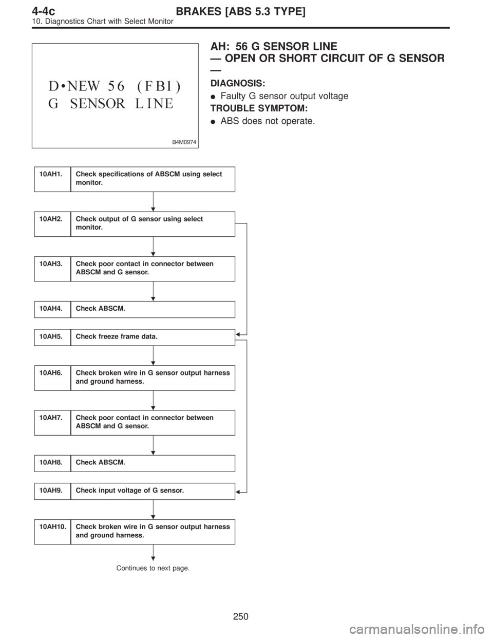
B4M0974
AH: 56 G SENSOR LINE
—OPEN OR SHORT CIRCUIT OF G SENSOR
—
DIAGNOSIS:
�Faulty G sensor output voltage
TROUBLE SYMPTOM:
�ABS does not operate.
10AH1.Check specifications of ABSCM using select
monitor.
�
�
10AH2.Check output of G sensor using select
monitor.
10AH3.Check poor contact in connector between
ABSCM and G sensor.
10AH4.Check ABSCM.
10AH5.Check freeze frame data.
10AH6.Check broken wire in G sensor output harness
and ground harness.
10AH7.Check poor contact in connector between
ABSCM and G sensor.
10AH8.Check ABSCM.
10AH9.Check input voltage of G sensor.
10AH10.Check broken wire in G sensor output harness
and ground harness.
Continues to next page.
�
�
�
�
�
�
�
�
250
4-4cBRAKES [ABS 5.3 TYPE]
10. Diagnostics Chart with Select Monitor
Page 2856 of 3342
From the former page.
10AH11.
Check ground short in G sensor output
harness.
10AH12.Check G sensor.
10AH13.Check poor contact in connector between
ABSCM and G sensor.
10AH14.Check ABSCM.
WIRING DIAGRAM:
B4M1050
�
�
�
�
251
4-4cBRAKES [ABS 5.3 TYPE]
10. Diagnostics Chart with Select Monitor
Page 2857 of 3342
 Press
F,
0and
0on the select monitor.
2) Read the select monitor display.
: Is an ABSCM for 4WD model installed on a
FWD model?
: Re")
B4M0921
10AH1CHECK SPECIFICATIONS OF ABSCM
USING SELECT MONITOR.
1) Press
F,
0and
0on the select monitor.
2) Read the select monitor display.
: Is an ABSCM for 4WD model installed on a
FWD model?
: Replace ABSCM.
: Go to step10AH2.
B4M0927
10AH2CHECK OUTPUT OF G SENSOR USING
SELECT MONITOR.
1) Press
F,
1and
0on the select monitor.
2) Read the select monitor display.
: Is the indicated reading 2.3±0.2 V when the
G sensor is in horizontal position?
: Go to step10AH3.
: Go to step10AH5.
10AH3CHECK POOR CONTACT IN CONNEC-
TOR BETWEEN ABSCM AND G SENSOR.
: Is there poor contact in connector between
ABSCM and G sensor?
: Repair connector.
: Go to step10AH4.
10AH4
CHECK ABSCM.
1) Connect all connectors.
2) Erase the memory.
3) Perform inspection mode.
4) Read out the trouble code.
: Is the same trouble code as in the current
diagnosis still being output?
: Replace ABSCM.
: Go to next.
: Are other trouble codes being output?
: Proceed with the diagnosis corresponding to the
trouble code.
: A temporary poor contact.
252
4-4cBRAKES [ABS 5.3 TYPE]
10. Diagnostics Chart with Select Monitor
 Connect all connectors.
2) Erase the memory.
3) Perform inspection mode.
4) Read out the trouble code.
: Is the same trouble code as in the current
diagnosis still being output?")
![SUBARU LEGACY 1997 Service Repair Manual WIRING DIAGRAM:
B4M1041
247
4-4cBRAKES [ABS 5.3 TYPE]
10. Diagnostics Chart with Select Monitor](/manual-img/17/57434/w960_57434-2851.png "SUBARU LEGACY 1997 Service Repair Manual WIRING DIAGRAM:
B4M1041
247
4-4cBRAKES [ABS 5.3 TYPE]
10. Diagnostics Chart with Select Monitor")