Page 2437 of 3342
G: TROUBLE CODE 22
—MASS AIR FLOW SIGNAL—
DIAGNOSIS:
Input signal circuit of TCM from ECM is open or shorted.
1. Check trouble code on engine side.
[T10B0], [T11B0].>
OK
�Not OK
Check for cause of trouble in engine.
2. Check harness connector between TCM and
ECM.
OK
�Not OK
Repair TCM connector terminal poor contact.
3. Check input signal for TCM.
OK
�Not OK
�Replace TCM.
Clear memory,Confirmation test,Not OK,
Repair TCM connector terminal poor contact.
B3M0475
1. CHECK TROUBLE CODE ON ENGINE SIDE.
Using Subaru select monitor or OBD-general scan tool,
check trouble code of mass air flow sensor on engine side.
�
�
�
33
3-2AUTOMATIC TRANSMISSION AND DIFFERENTIAL
7. Diagnostic Chart with Trouble Code
Page 2438 of 3342
 Turn ignition switch to OFF.
2) Disconnect connectors from TCM and ECM.
3) Measure resistance of harness connector between
TCM and ECM.
Conn")
B3M0476A
2. CHECK HARNESS CONNECTOR BETWEEN TCM
AND ECM.
1) Turn ignition switch to OFF.
2) Disconnect connectors from TCM and ECM.
3) Measure resistance of harness connector between
TCM and ECM.
Connector & terminal / Specified resistance:
(B54) No. 9—(B84) No. 47 / 1Ω, or less
B3M0224B
4) Measure resistance of harness connector between
TCM and body to make sure that circuit does not short.
Connector & terminal / Specified resistance:
(B54) No. 9—Body/1MΩ, or more
B3M0222B
3. CHECK INPUT SIGNAL FOR TCM.
1) Connect connectors to TCM and ECM.
2) Start the engine. (engine idling after warm-up)
3) Measure signal voltage between TCM connector termi-
nal and body.
Connector & terminal / Specified voltage:
Engine warm-up;
(B54) No. 9—Body / 0.5—1.22 V
OBD0145A
�Using Subaru select monitor:
(1) Connect connectors to TCM and ECM.
(2) Turn ignition switch to OFF.
(3) Connect the Subaru select monitor to data link con-
nector.
(4) Turn ignition switch to ON and Subaru select moni-
tor switch to ON.
(5) Start and warm-up the engine.
B3M0370
(6) Read data on Subaru select monitor.
(7) Designate mode using function key.
Function mode: F15
SPECIFIED DATA:
0.5—1.22 V (Engine warm-up)
34
3-2AUTOMATIC TRANSMISSION AND DIFFERENTIAL
7. Diagnostic Chart with Trouble Code
Page 2439 of 3342
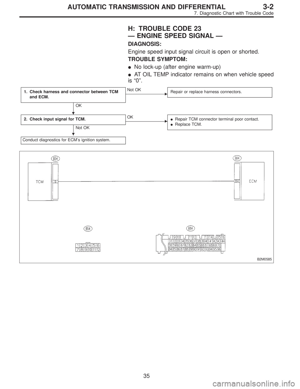
H: TROUBLE CODE 23
—ENGINE SPEED SIGNAL—
DIAGNOSIS:
Engine speed input signal circuit is open or shorted.
TROUBLE SYMPTOM:
�No lock-up (after engine warm-up)
�AT OIL TEMP indicator remains on when vehicle speed
is“0”.
1. Check harness and connector between TCM
and ECM.
OK
�Not OK
Repair or replace harness connectors.
2. Check input signal for TCM.
Not OK
�OK
�Repair TCM connector terminal poor contact.
�Replace TCM.
Conduct diagnostics for ECM’s ignition system.
B2M0585
�
�
35
3-2AUTOMATIC TRANSMISSION AND DIFFERENTIAL
7. Diagnostic Chart with Trouble Code
Page 2440 of 3342
 Turn ignition switch to OFF.
2) Disconnect connectors from TCM and ECM.
3) Measure resistance of harness connector between
TCM and ECM.")
B3M0477A
1. CHECK HARNESS AND CONNECTOR BETWEEN
TCM AND ECM.
1) Turn ignition switch to OFF.
2) Disconnect connectors from TCM and ECM.
3) Measure resistance of harness connector between
TCM and ECM.
Connector & terminal / Specified resistance:
(B54) No. 5—(B84) No. 64 / 1Ω, or less
OBD0410A
4) Measure resistance of harness connector between
TCM and body to make sure that circuit does not short.
Connector & terminal / Specified resistance:
(B54) No. 5—Body/1MΩ, or more
OBD0406A
2. CHECK INPUT SIGNAL FOR TCM.
1) Connect connectors to ECM and TCM.
2) Turn ignition switch ON (with engine OFF).
3) Measure signal voltage for TCM.
Connector & terminal / Specified voltage:
(B54) No. 5—Body / 10.5 V, or more
OBD0145A
�Using Subaru select monitor:
(1) Connect connectors to ECM and TCM.
(2) Turn ignition switch to OFF.
(3) Connect the Subaru select monitor to data link con-
nector.
(4) Turn ignition switch to ON and Subaru select moni-
tor switch to ON.
G3M0727
(5) Start and warm-up the engine.
(6) Operate at constant engine speed.
(7) Read data on Subaru select monitor.
(8) Designate mode using function key.
Function mode: F06
SPECIFIED DATA:
Same as tachometer reading (in combination
meter)
36
3-2AUTOMATIC TRANSMISSION AND DIFFERENTIAL
7. Diagnostic Chart with Trouble Code
Page 2441 of 3342
I: TROUBLE CODE 24
—DUTY SOLENOID C—
DIAGNOSIS:
Output signal circuit of duty solenoid C is open or shorted.
TROUBLE SYMPTOM:
Excessive“braking”in tight corners
1. Check harness and connectors between TCM
and duty solenoid C.
OK
�Not OK
Repair or replace harness connectors.
2. Check duty solenoid C’s ground line.
OK
�Not OK
Repair ground line.
3. Check duty solenoid C.
OK
�Not OK
Replace duty solenoid C.
�Repair TCM connector terminal poor contact.
�Replace TCM.
B3M0371
�
�
�
37
3-2AUTOMATIC TRANSMISSION AND DIFFERENTIAL
7. Diagnostic Chart with Trouble Code
Page 2442 of 3342
B3M0230B
1. CHECK HARNESS AND CONNECTORS BETWEEN
TCM AND DUTY SOLENOID C.
1) Turn ignition switch to OFF.
2) Disconnect connectors from TCM and transmission.
3) Measure resistance of harness connector between
TCM and transmission.
Connector & terminal / Specified resistance:
(B55) No. 3—(B11) No. 11 / 1Ω, or less
B3M0231B
4) Measure resistance of harness connector between
TCM and body to make sure that circuit does not short.
Connector & terminal / Specified resistance:
(B55) No. 3—Body/1MΩ, or more
G3M0109
2. CHECK DUTY SOLENOID C’s GROUND LINE.
Measure resistance between transmission connector
receptacle and transmission case.
Connector & terminal / Specified resistance:
(T4) No. 4—Transmission / 1Ω, or less
G3M0132
3. CHECK DUTY SOLENOID C.
Measure resistance between transmission connector
receptacle’s terminals.
Connector & terminal / Specified resistance:
(T4) No. 11—No.4/9—17Ω
38
3-2AUTOMATIC TRANSMISSION AND DIFFERENTIAL
7. Diagnostic Chart with Trouble Code
Page 2443 of 3342
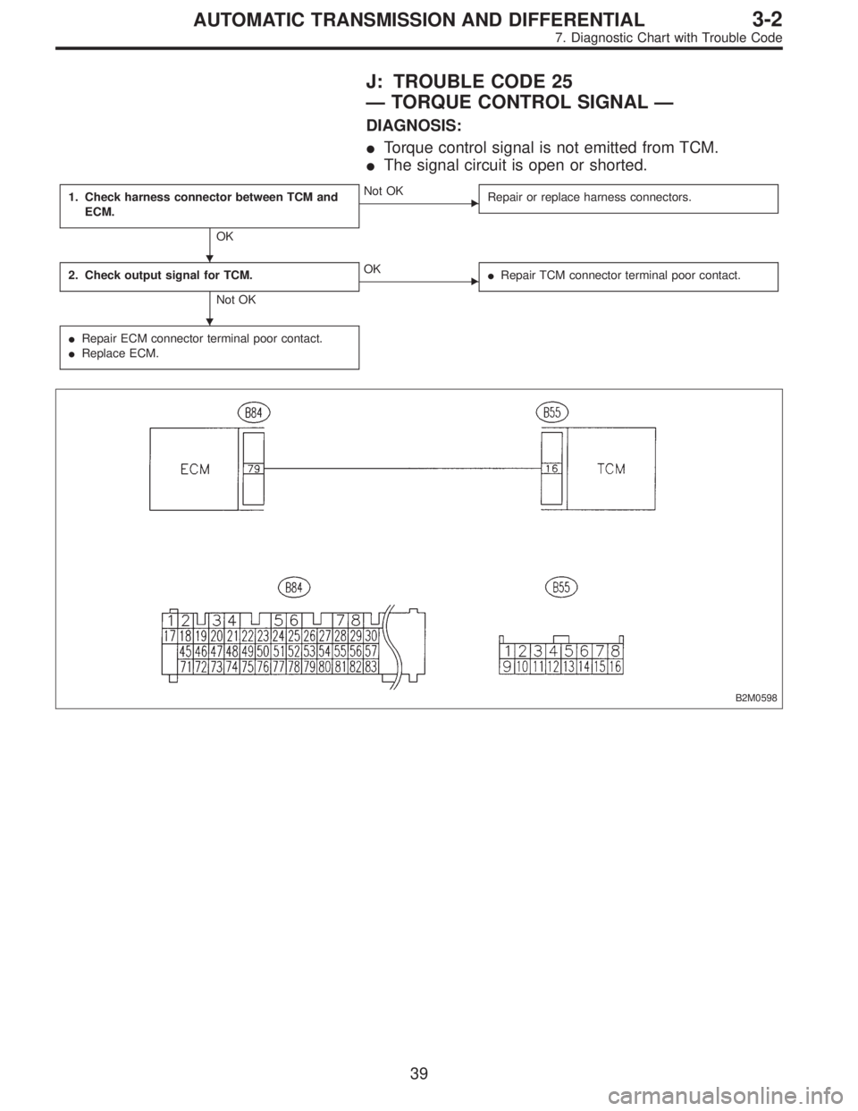
J: TROUBLE CODE 25
—TORQUE CONTROL SIGNAL—
DIAGNOSIS:
�Torque control signal is not emitted from TCM.
�The signal circuit is open or shorted.
1. Check harness connector between TCM and
ECM.
OK
�Not OK
Repair or replace harness connectors.
2. Check output signal for TCM.
Not OK
�OK
�Repair TCM connector terminal poor contact.
�Repair ECM connector terminal poor contact.
�Replace ECM.
B2M0598
�
�
39
3-2AUTOMATIC TRANSMISSION AND DIFFERENTIAL
7. Diagnostic Chart with Trouble Code
Page 2444 of 3342
B3M0478A
1. CHECK HARNESS CONNECTOR BETWEEN TCM
AND ECM.
1) Turn ignition switch to OFF.
2) Disconnect connectors from TCM and ECM.
3) Measure resistance of harness connector between
TCM and ECM.
Connector & terminal / Specified resistance:
(B55) No. 16—(B84) No. 79 / 1Ω, or less
B3M0235B
4) Measure resistance of harness connector between
TCM and body to make sure that circuit does not short.
Connector & terminal / Specified resistance:
(B55) No. 16—Body/1MΩ, or more
B3M0233B
2. CHECK OUTPUT SIGNAL FOR TCM.
1) Connect connectors to TCM and ECM.
2) Turn ignition switch to ON.
3) Measure signal voltage between TCM connector termi-
nal and body.
Connector & terminal / Specified voltage:
(B55) No. 16—Body / 5±1 V
40
3-2AUTOMATIC TRANSMISSION AND DIFFERENTIAL
7. Diagnostic Chart with Trouble Code


 Turn ignition switch to OFF.
2) Disconnect connectors from TCM and transmission.
3) Measure resistance of harness connector")
 Turn ignition switch to OFF.
2) Disconnect connectors from TCM and ECM.
3) Measure resistance of harness connector between
TCM and ECM.
Conn")