Page 2445 of 3342
K: TROUBLE CODE 31
—THROTTLE POSITION SENSOR—
DIAGNOSIS:
Input signal circuit of throttle position sensor is open or
shorted.
TROUBLE SYMPTOM:
Shift point too high or too low; engine brake not effected in
“3”range; excessive shift shock; excessive tight corner
“braking”
1. Check harness connector between TCM and
throttle position sensor.
OK
�Not OK
Repair or replace harness connectors.
2. Check throttle position sensor.
OK
�Not OK
Replace throttle position sensor.
3. Check input signal for TCM.
Not OK
�OK
�Repair TCM connector terminal poor contact.
�Replace TCM.
4. Check power supply to throttle position
sensor.
OK
�Not OK
Repair or replace harness connectors.
�Repair TCM connector terminal poor contact.
�Replace TCM.
B2M0613
�
�
�
�
41
3-2AUTOMATIC TRANSMISSION AND DIFFERENTIAL
7. Diagnostic Chart with Trouble Code
Page 2446 of 3342
 Turn ignition switch to OFF.
2) Disconnect connector from TCM and throttle position
sensor.
3) Measure resistance of ha")
OBD0507A
1. CHECK HARNESS CONNECTOR BETWEEN TCM
AND THROTTLE POSITION SENSOR.
1) Turn ignition switch to OFF.
2) Disconnect connector from TCM and throttle position
sensor.
3) Measure resistance of harness connector between
TCM and throttle position sensor.
Connector & terminal / Specified resistance:
(B54) No. 8—(E13) No.2/1Ω, or less
(B56) No. 19—(E13) No.3/1Ω, or less
B3M0382A
4) Measure resistance of harness connector between
TCM and body to make sure that circuit does not short.
Connector & terminal / Specified resistance:
(B54) No. 8—Body/1MΩ, or more
(B56) No. 19—Body/1MΩ, or more
OBD0510A
2. CHECK THROTTLE POSITION SENSOR.
Measure resistance between throttle position sensor termi-
nals.
Terminals / Specified resistance:
(E13) No. 1—No. 2 / 0.3—0.7 kΩ
(Throttle fully closed.)
3—6kΩ
(Throttle fully open.)
(E13) No. 1—No. 3 / 3.5—6.5 kΩ
OBD0503A
3. CHECK INPUT SIGNAL FOR TCM.
1) Connect connectors to TCM and throttle position sen-
sor.
2) Turn ignition switch ON (with engine OFF).
3) Measure signal voltage input emitted from throttle posi-
tion sensor with accelerator pedal fully depressed.
Connector & terminal / Specified voltage:
(B54) No. 8—No.7/
0.5±0.2 V (Throttle fully closed.)
4.6±0.3 V (Throttle fully open.)
OBD0145A
�Using Subaru select monitor:
(1) Connect connectors to TCM and throttle position
sensor.
(2) Turn ignition switch to OFF.
(3) Connect the Subaru select monitor to data link con-
nector.
(4) Turn ignition switch to ON and Subaru select moni-
tor switch to ON.
42
3-2AUTOMATIC TRANSMISSION AND DIFFERENTIAL
7. Diagnostic Chart with Trouble Code
Page 2447 of 3342
 Designate mode using function key.
(6) Read data on Subaru select monitor.
Function mode: F09
SPECIFIED DATA:
0.5±0.2 V (Throttle fully closed.)
4.6±0.3 V (Throttle fully open.)
[Must be")
B3M0383
(5) Designate mode using function key.
(6) Read data on Subaru select monitor.
Function mode: F09
SPECIFIED DATA:
0.5±0.2 V (Throttle fully closed.)
4.6±0.3 V (Throttle fully open.)
[Must be changed correspondingly with accelera-
tor pedal operation (from“released”to
“depressed”position).]
B3M0238A
4. CHECK POWER SUPPLY TO THROTTLE POSITION
SENSOR.
1) Turn ignition switch to OFF.
2) Disconnect connector from throttle position sensor.
3) Turn ignition switch to ON.
4) Measure power supply voltage to throttle position sen-
sor.
Connector & terminal / Specified voltage:
(E13) No. 1—Body / 5.12±0.1 V
OBD0145A
�Using Subaru select monitor:
(1) Turn ignition switch to OFF.
(2) Connect the Subaru select monitor to data link con-
nector.
(3) Turn ignition switch to ON and Subaru select moni-
tor switch to ON.
OBD0506
(4) Designate mode using function key.
(5) Read data on Subaru select monitor.
Function mode: F14
SPECIFIED DATA:
5.12±0.1 V
43
3-2AUTOMATIC TRANSMISSION AND DIFFERENTIAL
7. Diagnostic Chart with Trouble Code
Page 2448 of 3342
L: TROUBLE CODE 32
—VEHICLE SPEED SENSOR 1—
DIAGNOSIS:
Input signal circuit of TCM is open or shorted.
TROUBLE SYMPTOM:
No locking-up or excessive tight corner“braking”
1. Check harness connector between TCM and
vehicle speed sensor 1.
OK
�Not OK
Repair or replace harness connectors.
2. Check vehicle speed sensor 1.
OK
�Not OK
Replace vehicle speed sensor 1.
3. Check input signal for TCM.
OK
�Not OK
�Repair TCM connector terminal poor contact.
�Replace TCM.
When trouble code 32 reappears.
Mechanical trouble between vehicle speed sensor 1
and sprocket
B3M0412
�
�
�
44
3-2AUTOMATIC TRANSMISSION AND DIFFERENTIAL
7. Diagnostic Chart with Trouble Code
Page 2449 of 3342
 Turn ignition switch to OFF.
2) Disconnect connectors from TCM and transmission.
3) Measure resistance of harness connect")
OBD0400A
1. CHECK HARNESS CONNECTOR BETWEEN TCM
AND VEHICLE SPEED SENSOR 1.
1) Turn ignition switch to OFF.
2) Disconnect connectors from TCM and transmission.
3) Measure resistance of harness connector between
TCM and transmission connector.
Connector & terminal / Specified resistance:
(B54) No. 12—(B11) No. 16 / 1Ω, or less
(B54) No. 7—(B11)No.9/1Ω, or less
OBD0401A
4) Measure resistance of harness connector between
TCM and body to make sure that circuit does not short.
Connector & terminal / Specified resistance:
(B54) No. 7—Body/1MΩ, or more
(B54) No. 12—Body/1MΩ, or more
G3M0140
2. CHECK VEHICLE SPEED SENSOR 1.
1) Measure resistance between transmission connector
receptacle’s terminals.
Connector & terminal / Specified resistance:
(T4) No. 16—No. 9 / 450—720Ω
OBD0403A
2) Measure resistance of harness connector between
transmission connector and transmission case to make
sure that circuit does not short.
Connector & terminal / Specified resistance:
(T4) No. 16—Transmission / 1 MΩ, or more
(T4) No. 9—Transmission / 1 MΩ, or more
45
3-2AUTOMATIC TRANSMISSION AND DIFFERENTIAL
7. Diagnostic Chart with Trouble Code
Page 2450 of 3342
 Connect connectors to TCM and transmission.
2) Lift-up or raise the vehicle and place safety stands.
CAUTION:
On AWD models, raise all wheels off floor.
3) P")
OBD0396A
3. CHECK INPUT SIGNAL FOR TCM.
1) Connect connectors to TCM and transmission.
2) Lift-up or raise the vehicle and place safety stands.
CAUTION:
On AWD models, raise all wheels off floor.
3) Push the TCS OFF switch to ON. (With TCS models)
4) Start the engine and set vehicle in 20 km/h (12 MPH)
condition.
5) Measure voltage between TCM connector terminals.
Connector & terminal / Specified voltage:
(B54) No. 12—No. 7 / AC 1 V, or more
NOTE:
The speed difference between front and rear wheels may
light either the ABS or the ABS/TCS warning light, but this
indicates no malfunctions. When AT control diagnosis is
finished, perform the ABS or the ABS/TCS memory clear-
ance procedure of self-diagnosis system.
or 4-4d [T6D2] or [T9J0].>
OBD0145A
B3M0413
OBD0399
�Using Subaru select monitor:
(1) Connect connectors to TCM and transmission.
(2) Turn ignition switch to OFF.
(3) Connect the Subaru select monitor to data link con-
nector.
(4) Lift-up or raise the vehicle and place safety stands.
CAUTION:
On AWD models, raise all wheels off floor.
(5) Turn ignition switch to ON and Subaru select moni-
tor switch to ON.
(6) Push the TCS OFF switch to ON. (With TCS mod-
els)
(7) Start the engine and operate at constant speed.
(8) Read data on Subaru select monitor.
(9) Designate mode using function key.
Function mode: F02 or F03
SPECIFIED DATA:
F02: Compare speedometer with monitor indica-
tions.
F03: Compare speedometer with monitor indica-
tions.
�F02: Vehicle speed is indicated in“m/h”.
�F03: Vehicle speed is indicated in“km/h”.
NOTE:
The speed difference between front and rear wheels may
light either the ABS or the ABS/TCS warning light, but this
indicates no malfunctions. When AT control diagnosis is
finished, perform the ABS or the ABS/TCS memory clear-
ance procedure of self-diagnosis system.
or 4-4d [T6D2] or [T9J0].>
46
3-2AUTOMATIC TRANSMISSION AND DIFFERENTIAL
7. Diagnostic Chart with Trouble Code
Page 2451 of 3342
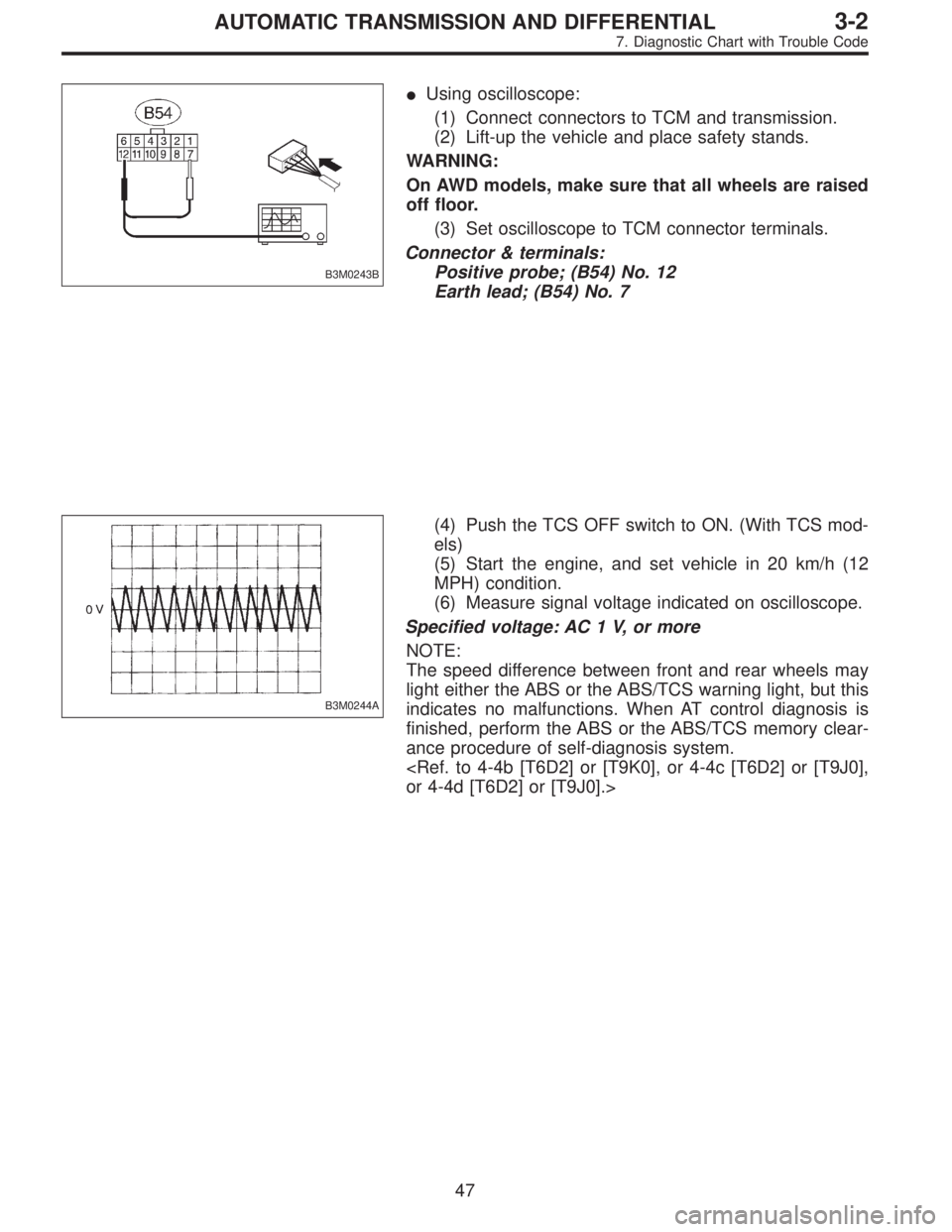
B3M0243B
�Using oscilloscope:
(1) Connect connectors to TCM and transmission.
(2) Lift-up the vehicle and place safety stands.
WARNING:
On AWD models, make sure that all wheels are raised
off floor.
(3) Set oscilloscope to TCM connector terminals.
Connector & terminals:
Positive probe; (B54) No. 12
Earth lead; (B54) No. 7
B3M0244A
(4) Push the TCS OFF switch to ON. (With TCS mod-
els)
(5) Start the engine, and set vehicle in 20 km/h (12
MPH) condition.
(6) Measure signal voltage indicated on oscilloscope.
Specified voltage: AC 1 V, or more
NOTE:
The speed difference between front and rear wheels may
light either the ABS or the ABS/TCS warning light, but this
indicates no malfunctions. When AT control diagnosis is
finished, perform the ABS or the ABS/TCS memory clear-
ance procedure of self-diagnosis system.
or 4-4d [T6D2] or [T9J0].>
47
3-2AUTOMATIC TRANSMISSION AND DIFFERENTIAL
7. Diagnostic Chart with Trouble Code
Page 2452 of 3342

M: TROUBLE CODE 33
—VEHICLE SPEED SENSOR 2—
DIAGNOSIS:
�The vehicle speed signal is abnormal.
�The circuit in combination meter is faulty.
�The harness connector between TCM and vehicle speed
sensor is in short or open.
TROUBLE SYMPTOM:
�Erroneous idling
�Engine stalls.
�Poor driving performance
1. Check operation of speedometer.
OK
�Not OK
Check combination meter circuit.
2. Check harness connector between TCM and
combination meter.
OK
�Not OK
Repair or replace harness connector.
3. Check vehicle speed sensor 2.
OK
�Not OK
�Mechanical trouble between vehicle speed sensor
2 and speedometer shaft in transmission
�Failure of the vehicle speed sensor 2
,Replace vehicle speed sensor 2.
4. Check input signal for TCM.
OK
�Not OK
�Repair TCM connector terminal poor contact.
�Replace TCM.
When trouble code 33 reappears after clearing
memory, repair TCM connector terminal poor
contact.
B3M0640
�
�
�
�
48
3-2AUTOMATIC TRANSMISSION AND DIFFERENTIAL
7. Diagnostic Chart with Trouble Code