Page 1930 of 3342
5. Specified Data
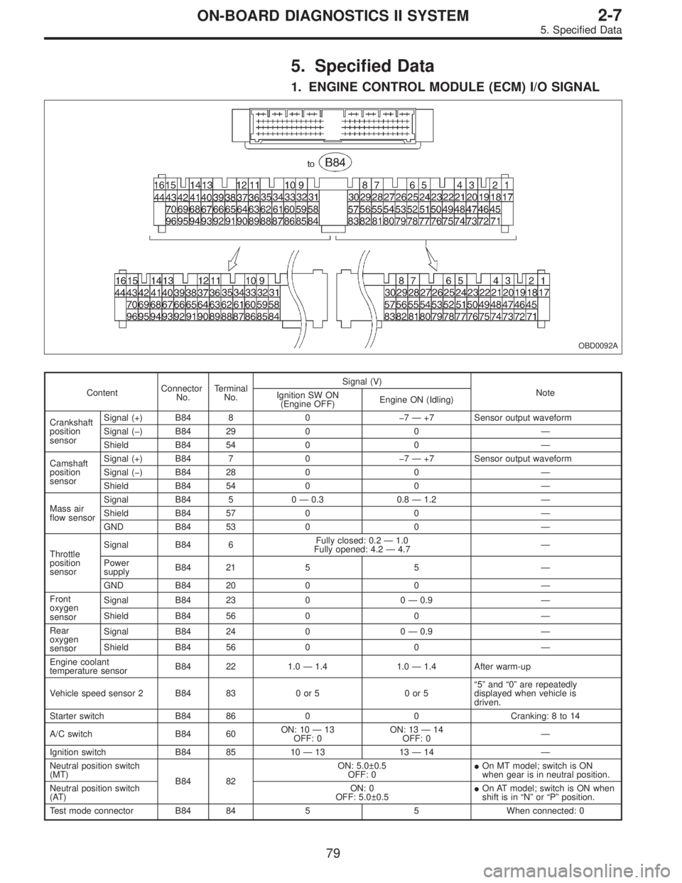
1. ENGINE CONTROL MODULE (ECM) I/O SIGNAL
OBD0092A
ContentConnector
No.Terminal
No.Signal (V)
Note
Ignition SW ON
(Engine OFF)Engine ON (Idling)
Crankshaft
position
sensorSignal (+) B84 8 07—+7 Sensor output waveform
Signal () B84 29 0 0—
Shield B84 54 0 0—
Camshaft
position
sensorSignal (+) B84 7 07—+7 Sensor output waveform
Signal () B84 28 0 0—
Shield B84 54 0 0—
Mass air
flow sensorSignal B84 5 0—0.3 0.8—1.2—
Shield B84 57 0 0—
GND B84 53 0 0—
Throttle
position
sensorSignal B84 6Fully closed: 0.2—1.0
Fully opened: 4.2—4.7—
Power
supplyB84 21 5 5—
GND B84 20 0 0—
Front
oxygen
sensorSignal B84 23 0 0—0.9—
Shield B84 56 0 0—
Rear
oxygen
sensorSignal B84 24 0 0—0.9—
Shield B84 56 0 0—
Engine coolant
temperature sensorB84 22 1.0—1.4 1.0—1.4 After warm-up
Vehicle speed sensor 2 B84 83 0 or 5 0 or 5“5”and“0”are repeatedly
displayed when vehicle is
driven.
Starter switch B84 86 0 0 Cranking: 8 to 14
A/C switch B84 60ON: 10—13
OFF: 0ON: 13—14
OFF: 0—
Ignition switch B84 85 10—13 13—14—
Neutral position switch
(MT)
B84 82ON: 5.0±0.5
OFF: 0�On MT model; switch is ON
when gear is in neutral position.
Neutral position switch
(AT)ON: 0
OFF: 5.0±0.5�On AT model; switch is ON when
shift is in“N”or“P”position.
Test mode connector B84 84 5 5 When connected: 0
79
2-7ON-BOARD DIAGNOSTICS II SYSTEM
5. Specified Data
Page 1947 of 3342
8. Diagnostics for Engine Starting
Failure
A: BASIC DIAGNOSTICS CHART
Inspection of starter motor circuit.
Inspection of ECM power supply and ground line.
Inspection of ignition control system.
Inspection of fuel pump circuit.
Inspection of fuel injector circuit.
Inspection of crankshaft position sensor circuit.
Inspection of camshaft position sensor circuit.
Inspection using Subaru select monitor or OBD-II
general scan tool or inspection using“9. General
Diagnostics Table.
�
�
�
�
�
�
�
96
2-7ON-BOARD DIAGNOSTICS II SYSTEM
8. Diagnostics for Engine Starting Failure
Page 1948 of 3342
B: STARTER MOTOR CIRCUIT
WIRING DIAGRAM:
B2M1047
CAUTION:
After repair or replacement of faulty parts, conduct
CLEAR MEMORY and INSPECTION MODES.
OBD0724
8B1CHECK INPUT SIGNAL FOR STARTER
MOTOR.
1) Turn ignition switch to OFF.
2) Disconnect connector from starter motor.
3) Turn ignition switch to ST.
97
2-7ON-BOARD DIAGNOSTICS II SYSTEM
8. Diagnostics for Engine Starting Failure
Page 1949 of 3342
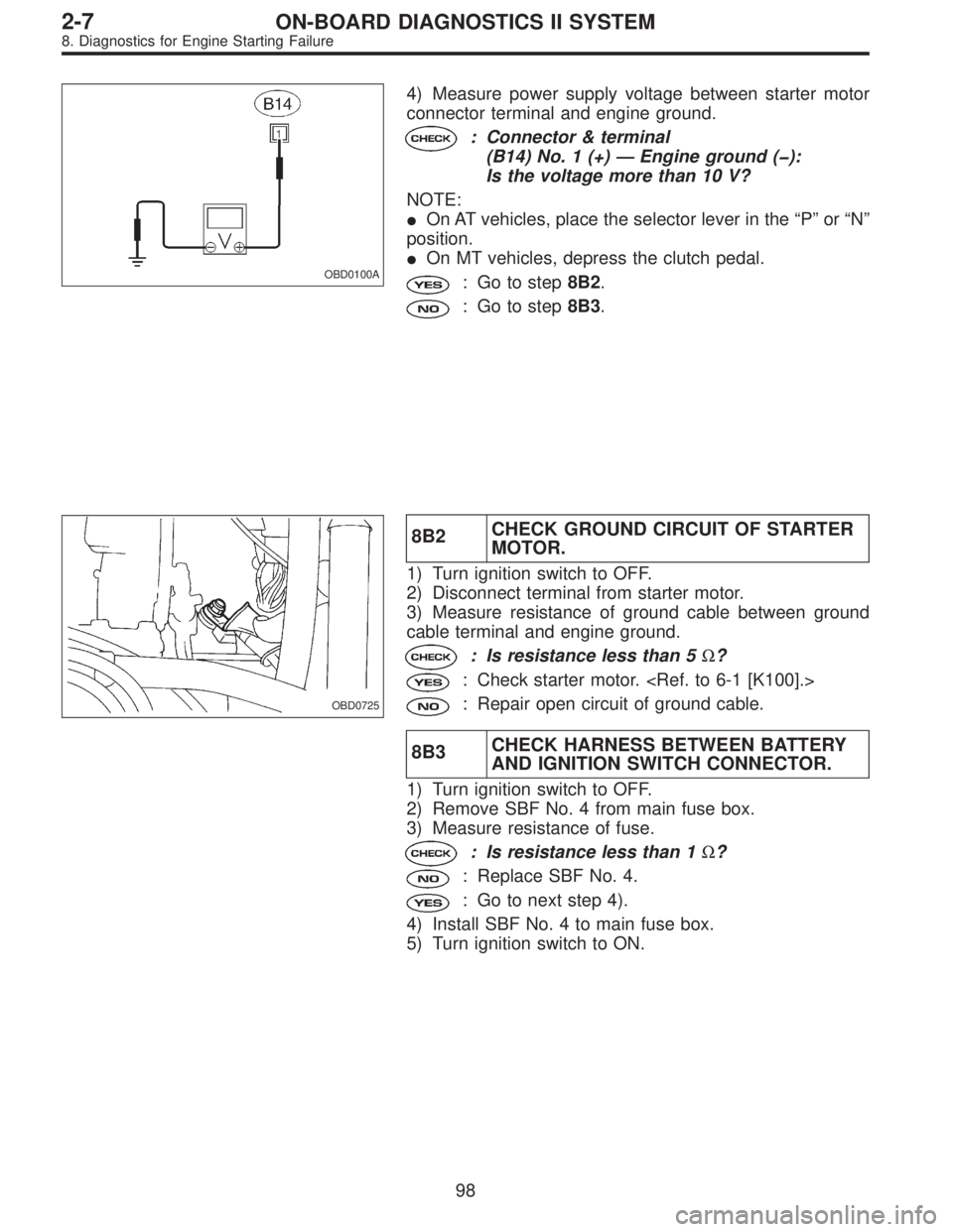
OBD0100A
4) Measure power supply voltage between starter motor
connector terminal and engine ground.
: Connector & terminal
(B14) No. 1 (+)—Engine ground ():
Is the voltage more than 10 V?
NOTE:
�On AT vehicles, place the selector lever in the“P”or“N”
position.
�On MT vehicles, depress the clutch pedal.
: Go to step8B2.
: Go to step8B3.
OBD0725
8B2CHECK GROUND CIRCUIT OF STARTER
MOTOR.
1) Turn ignition switch to OFF.
2) Disconnect terminal from starter motor.
3) Measure resistance of ground cable between ground
cable terminal and engine ground.
: Is resistance less than 5Ω?
: Check starter motor.
: Repair open circuit of ground cable.
8B3CHECK HARNESS BETWEEN BATTERY
AND IGNITION SWITCH CONNECTOR.
1) Turn ignition switch to OFF.
2) Remove SBF No. 4 from main fuse box.
3) Measure resistance of fuse.
: Is resistance less than 1Ω?
: Replace SBF No. 4.
: Go to next step 4).
4) Install SBF No. 4 to main fuse box.
5) Turn ignition switch to ON.
98
2-7ON-BOARD DIAGNOSTICS II SYSTEM
8. Diagnostics for Engine Starting Failure
Page 1950 of 3342
OBD0103A
6) Measure power supply voltage between ignition switch
connector and chassis ground.
: Connector & terminal
(B72) No. 1 (+)—Chassis ground ():
Is the voltage more than 10 V?
: Go to step8B4.
: Repair open circuit in harness between ignition
switch and SBF No. 4 connector.
8B4
CHECK TRANSMISSION TYPE.
: Is transmission type AT?
: Go to step8B5.
: Go to step8B9.
8B5
CHECK INHIBITOR SWITCH TYPE.
: Is inhibitor switch type plastic body?
: Go to step8B6.
: Go to step8B8.
B2M1279A
8B6
CHECK INHIBITOR SWITCH.
1) Turn ignition switch to OFF.
2) Place the selector lever in the“P”or“N”position.
3) Measure resistance between transmission harness
connector receptacle’s terminals.
: Connector & terminal
(T3) No. 11—No. 12:
Is the resistance less than 1Ω?
: Repair open circuit in harness between starter
motor and ignition switch connector.
: Go to step8B7.
99
2-7ON-BOARD DIAGNOSTICS II SYSTEM
8. Diagnostics for Engine Starting Failure
Page 1952 of 3342
B2M1279A
8B8
CHECK INHIBITOR SWITCH.
1) Turn ignition switch to OFF.
2) Place the selector lever in the“P”or“N”position.
3) Disconnect connector from transmission harness con-
nector.
4) Measure resistance between transmission harness
connector receptacle’s terminals.
: Connector & terminal
(T3) No. 11—No. 12:
Is the resistance less than 1Ω?
: Repair open circuit in harness between starter
motor and ignition switch connector.
: Replace inhibitor switch.
B2M0517A
8B9
CHECK STARTER INTERLOCK CIRCUIT.
1) Turn ignition switch to“ST”.
2) Measure voltage between clutch switch connector and
chassis ground.
: Connector & terminal
�With cruise control
(B107) No. 2 (+)—Chassis ground ():
�Without cruise control
(B106) No. 2 (+)—Chassis ground ():
Is the voltage more than 10 V?
: Replace starter interlock relay.
: Go to next step 3).
101
2-7ON-BOARD DIAGNOSTICS II SYSTEM
8. Diagnostics for Engine Starting Failure
Page 1953 of 3342
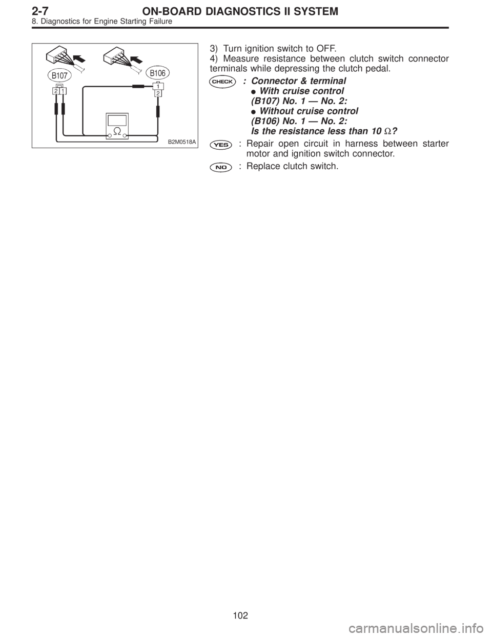
B2M0518A
3) Turn ignition switch to OFF.
4) Measure resistance between clutch switch connector
terminals while depressing the clutch pedal.
: Connector & terminal
�With cruise control
(B107) No. 1—No. 2:
�Without cruise control
(B106) No. 1—No. 2:
Is the resistance less than 10Ω?
: Repair open circuit in harness between starter
motor and ignition switch connector.
: Replace clutch switch.
102
2-7ON-BOARD DIAGNOSTICS II SYSTEM
8. Diagnostics for Engine Starting Failure
Page 1976 of 3342

B: GENERAL DIAGNOSTICS TABLE WITH
NONCONFORMITY SYMPTOM FOR
AUTOMATIC TRANSMISSION
Problem parts
Inhibitor switch
Control module
Vehicle speed sensor 1
Vehicle speed sensor 2
Select cable
Select lever
FWD switch
Starter motor and harness
Throttle position sensor
Hold switch
Accumulator (“N”—“D”)
Accumulator (2A)
Accumulator (4A)
Accumulator (3R)
ATF temperature sensor
Strainer
Duty solenoid A
Duty solenoid B
Shift solenoid 1
Shift solenoid 2
Shift solenoid 3
Control valve
Detent spring
Manual plate
Transfer clutch
Transfer valve
Transfer pipe
Duty solenoid C
Forward clutch
Symptom1234567891011121314151617181920212223242526272829
Starter does not rotate when select lever is
in“P”or“N.”; starter rotates when select
lever is“R”,“D”,“3”or“2.”����
Abnormal noise when select lever is in“P”or
“N.”��
Hissing noise occurs during standing starts.�
Noise occurs while driving in“D
1”range.
Noise occurs while driving in“D
2”range.
Noise occurs while driving in“D
3”range.
Noise occurs while driving in“D
4”range.
Engine stalls while shifting from one range to
another.�
Vehicle moves when select lever is in“N.”�
Shock occurs when select lever is moved
from“N”to“D.”�� �
Excessive time lag occurs when select lever
is moved from“N”to“D.”��
Shock occurs when select lever is moved
from“N”to“R.”���
Excessive time lag occurs when select lever
is moved from“N”to“R.”�
Vehicle does not start in any shift range
(engine revving up).��
Vehicle does not start in any shift range
(engine stall).
Vehicle does not start in“R”range only
(engine revving up).�� �
Vehicle does not start in“R”range only
(engine stall).�
Vehicle does not start in“D”or“3”range
(engine revving up).�
Vehicle does not start in“D”,“3”or“2”range
(engine revving up).�
Vehicle does not start in“D”,“3”or“2”range
(engine stall).
Vehicle starts in“R”range only (engine rev-
ving up).�
Acceleration during standing starts is poor
(high stall rpm).��
Acceleration during standing starts is poor
(low stall rpm).
Acceleration is poor when select lever is in
“D”,“3”or“2”range (normal stall rpm).��
Acceleration is poor when select lever is in
“R”(normal stall rpm).�
No shift occurs from 1st to 2nd gear.��� � �� �
No shift occurs from 2nd to 3rd gear.��
No shift occurs from 3rd to 4th gear.�����
No“kick-down”shifts occur.��
Engine brake is not effected when select
lever is in“3”range.�� � �
1234567891011121314151617181920212223242526272829
125
2-7ON-BOARD DIAGNOSTICS II SYSTEM
9. General Diagnostic Table