Page 1977 of 3342
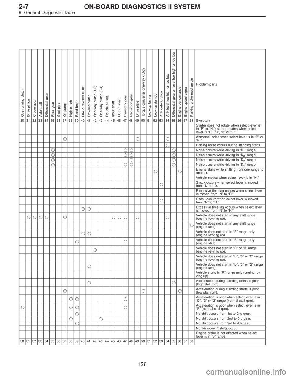
Overrunning clutch
Drive pinion
Crown gear
Axle shaft
Differential gear
Final gear
Seal pipe
Oil pump
High clutch
Band brake
Low & reverse clutch
Reverse clutch
One-way clutch (1-2)
One-way clutch (3-4)
Double oil seal
Input shaft
Output shaft
Planetary gear
Reduction gear
Drive plate
Torque converter one-way clutch
Lock-up facing
Lock-up damper
ATF deterioration
ATF level too high or too low
Differential gear oil level too high or too low
Engine performance
Engine speed signal
Parking brake mechanism
Problem parts
30 31 32 33 34 35 36 37 38 39 40 41 42 43 44 45 46 47 48 49 50 51 52 53 54 55 56 57 58 Symptom
Starter does not rotate when select lever is
in“P”or“N.”; starter rotates when select
lever is“R”,“D”,“3”or“2.”
���Abnormal noise when select lever is in“P”or
“N.”
�Hissing noise occurs during standing starts.
����Noise occurs while driving in“D
1”range.
����Noise occurs while driving in“D
2”range.
���Noise occurs while driving in“D
3”range.
����Noise occurs while driving in“D
4”range.
��Engine stalls while shifting from one range to
another.
Vehicle moves when select lever is in“N.”
�Shock occurs when select lever is moved
from“N”to“D.”
Excessive time lag occurs when select lever
is moved from“N”to“D.”
�Shock occurs when select lever is moved
from“N”to“R.”
��Excessive time lag occurs when select lever
is moved from“N”to“R.”
���� � ��� � �Vehicle does not start in any shift range
(engine revving up).
�Vehicle does not start in any shift range
(engine stall).
��Vehicle does not start in“R”range only
(engine revving up).
��Vehicle does not start in“R”range only
(engine stall).
�Vehicle does not start in“D”or“3”range
(engine revving up).
Vehicle does not start in“D”,“3”or“2”range
(engine revving up).
�Vehicle does not start in“D”,“3”or“2”range
(engine stall).
Vehicle starts in“R”range only (engine rev-
ving up).
��Acceleration during standing starts is poor
(high stall rpm).
���Acceleration during standing starts is poor
(low stall rpm).
�� �Acceleration is poor when select lever is in
“D”,“3”or“2”range (normal stall rpm).
����Acceleration is poor when select lever is in
“R”(normal stall rpm).
�No shift occurs from 1st to 2nd gear.
��No shift occurs from 2nd to 3rd gear.
�No shift occurs from 3rd to 4th gear.
No“kick-down”shifts occur.
Engine brake is not effected when select
lever is in“3”range.
30 31 32 33 34 35 36 37 38 39 40 41 42 43 44 45 46 47 48 49 50 51 52 53 54 55 56 57 58
126
2-7ON-BOARD DIAGNOSTICS II SYSTEM
9. General Diagnostic Table
Page 1978 of 3342
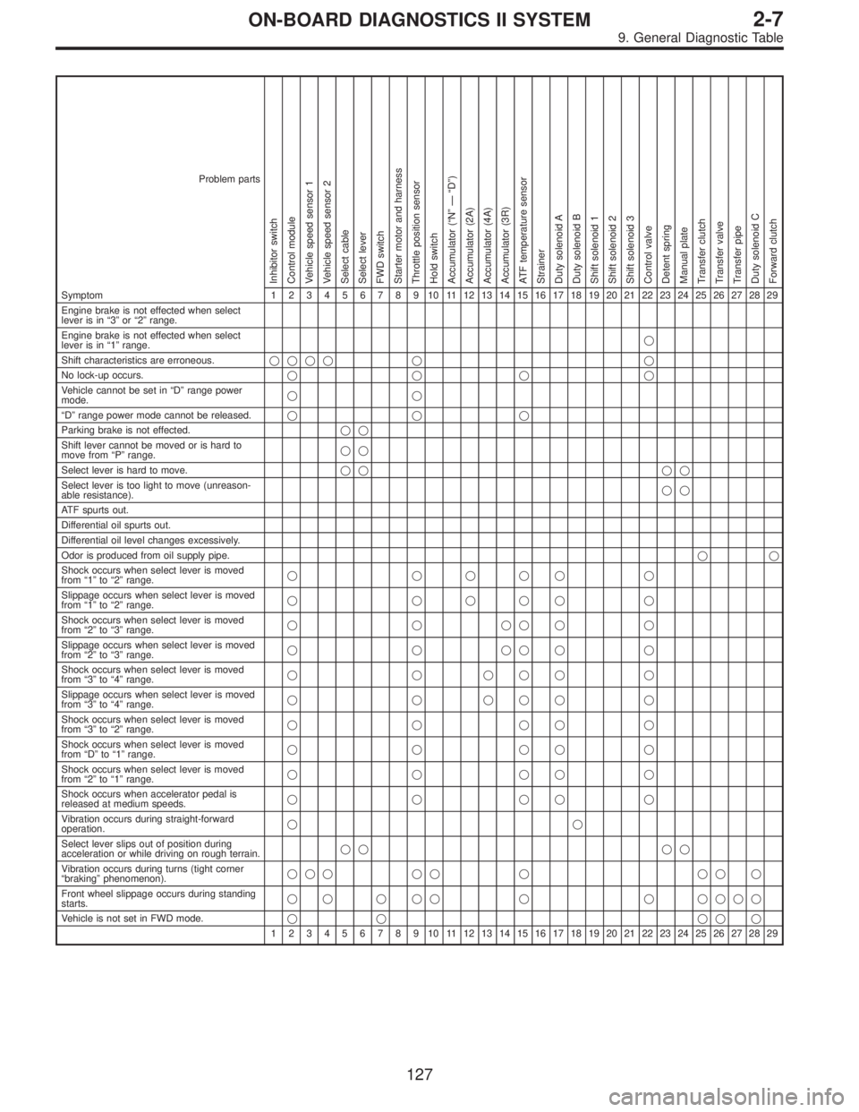
Problem parts
Inhibitor switch
Control module
Vehicle speed sensor 1
Vehicle speed sensor 2
Select cable
Select lever
FWD switch
Starter motor and harness
Throttle position sensor
Hold switch
Accumulator (“N”—“D”)
Accumulator (2A)
Accumulator (4A)
Accumulator (3R)
ATF temperature sensor
Strainer
Duty solenoid A
Duty solenoid B
Shift solenoid 1
Shift solenoid 2
Shift solenoid 3
Control valve
Detent spring
Manual plate
Transfer clutch
Transfer valve
Transfer pipe
Duty solenoid C
Forward clutch
Symptom1234567891011121314151617181920212223242526272829
Engine brake is not effected when select
lever is in“3”or“2”range.
Engine brake is not effected when select
lever is in“1”range.�
Shift characteristics are erroneous.���� � �
No lock-up occurs.����
Vehicle cannot be set in“D”range power
mode.��
“D”range power mode cannot be released.���
Parking brake is not effected.��
Shift lever cannot be moved or is hard to
move from“P”range.��
Select lever is hard to move.�� ��
Select lever is too light to move (unreason-
able resistance).��
ATF spurts out.
Differential oil spurts out.
Differential oil level changes excessively.
Odor is produced from oil supply pipe.��
Shock occurs when select lever is moved
from“1”to“2”range.� ���� �
Slippage occurs when select lever is moved
from“1”to“2”range.� ���� �
Shock occurs when select lever is moved
from“2”to“3”range.������
Slippage occurs when select lever is moved
from“2”to“3”range.������
Shock occurs when select lever is moved
from“3”to“4”range.� � ��� �
Slippage occurs when select lever is moved
from“3”to“4”range.� � ��� �
Shock occurs when select lever is moved
from“3”to“2”range.�����
Shock occurs when select lever is moved
from“D”to“1”range.�����
Shock occurs when select lever is moved
from“2”to“1”range.�����
Shock occurs when accelerator pedal is
released at medium speeds.�����
Vibration occurs during straight-forward
operation.��
Select lever slips out of position during
acceleration or while driving on rough terrain.�� ��
Vibration occurs during turns (tight corner
“braking”phenomenon).��� �� � �� �
Front wheel slippage occurs during standing
starts.� � � �� � � ����
Vehicle is not set in FWD mode.�� ���
1234567891011121314151617181920212223242526272829
127
2-7ON-BOARD DIAGNOSTICS II SYSTEM
9. General Diagnostic Table
Page 1981 of 3342
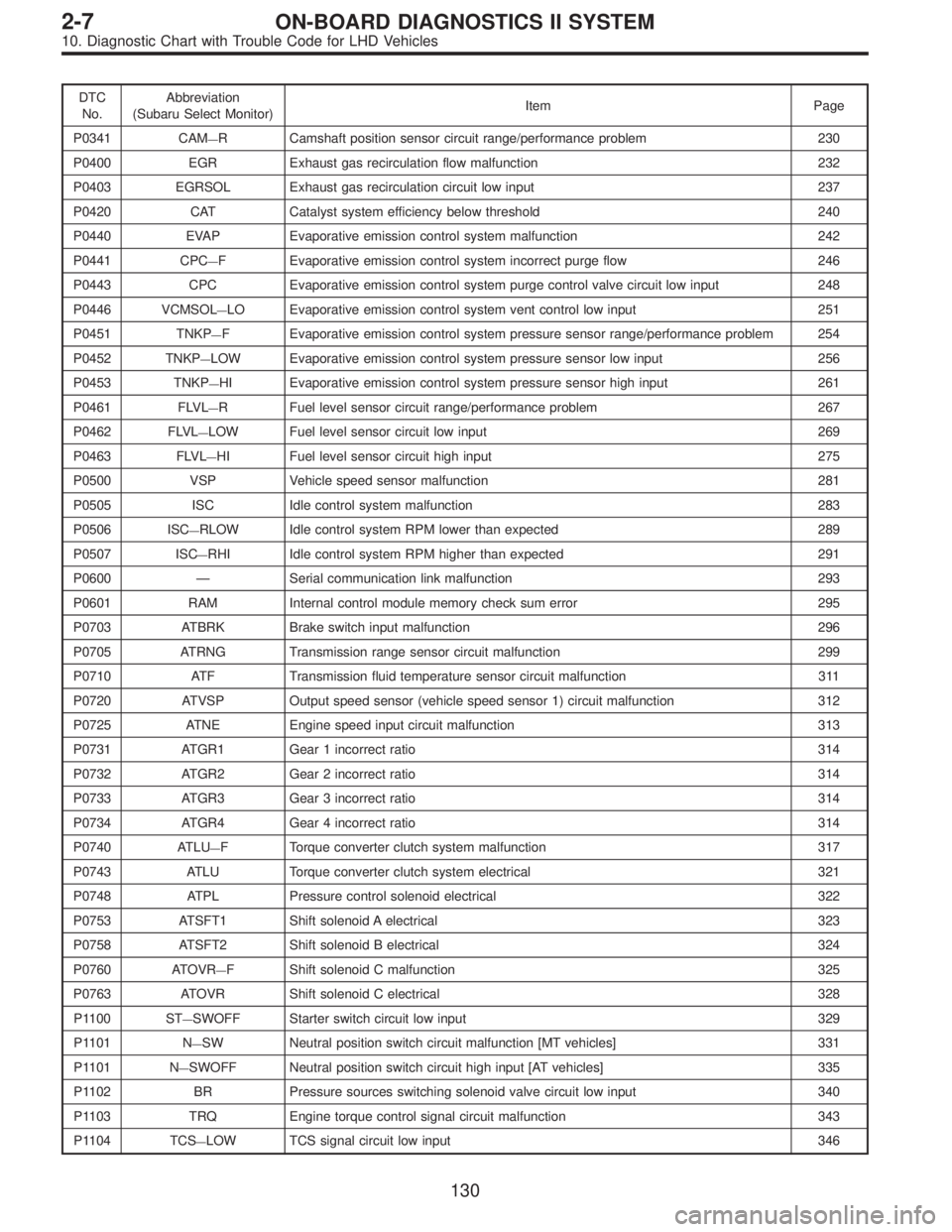
DTC
No.Abbreviation
(Subaru Select Monitor)Item Page
P0341 CAM
—R Camshaft position sensor circuit range/performance problem 230
P0400 EGR Exhaust gas recirculation flow malfunction 232
P0403 EGRSOL Exhaust gas recirculation circuit low input 237
P0420 CAT Catalyst system efficiency below threshold 240
P0440 EVAP Evaporative emission control system malfunction 242
P0441 CPC
—F Evaporative emission control system incorrect purge flow 246
P0443 CPC Evaporative emission control system purge control valve circuit low input 248
P0446 VCMSOL
—LO Evaporative emission control system vent control low input 251
P0451 TNKP
—F Evaporative emission control system pressure sensor range/performance problem 254
P0452 TNKP
—LOW Evaporative emission control system pressure sensor low input 256
P0453 TNKP
—HI Evaporative emission control system pressure sensor high input 261
P0461 FLVL
—R Fuel level sensor circuit range/performance problem 267
P0462 FLVL
—LOW Fuel level sensor circuit low input 269
P0463 FLVL
—HI Fuel level sensor circuit high input 275
P0500 VSP Vehicle speed sensor malfunction 281
P0505 ISC Idle control system malfunction 283
P0506 ISC
—RLOW Idle control system RPM lower than expected 289
P0507 ISC
—RHI Idle control system RPM higher than expected 291
P0600—Serial communication link malfunction 293
P0601 RAM Internal control module memory check sum error 295
P0703 ATBRK Brake switch input malfunction 296
P0705 ATRNG Transmission range sensor circuit malfunction 299
P0710 ATF Transmission fluid temperature sensor circuit malfunction 311
P0720 ATVSP Output speed sensor (vehicle speed sensor 1) circuit malfunction 312
P0725 ATNE Engine speed input circuit malfunction 313
P0731 ATGR1 Gear 1 incorrect ratio 314
P0732 ATGR2 Gear 2 incorrect ratio 314
P0733 ATGR3 Gear 3 incorrect ratio 314
P0734 ATGR4 Gear 4 incorrect ratio 314
P0740 ATLU
—F Torque converter clutch system malfunction 317
P0743 ATLU Torque converter clutch system electrical 321
P0748 ATPL Pressure control solenoid electrical 322
P0753 ATSFT1 Shift solenoid A electrical 323
P0758 ATSFT2 Shift solenoid B electrical 324
P0760 ATOVR
—F Shift solenoid C malfunction 325
P0763 ATOVR Shift solenoid C electrical 328
P1100 ST
—SWOFF Starter switch circuit low input 329
P1101 N
—SW Neutral position switch circuit malfunction [MT vehicles] 331
P1101 N
—SWOFF Neutral position switch circuit high input [AT vehicles] 335
P1102 BR Pressure sources switching solenoid valve circuit low input 340
P1103 TRQ Engine torque control signal circuit malfunction 343
P1104 TCS
—LOW TCS signal circuit low input 346
130
2-7ON-BOARD DIAGNOSTICS II SYSTEM
10. Diagnostic Chart with Trouble Code for LHD Vehicles
Page 1982 of 3342

DTC
No.Abbreviation
(Subaru Select Monitor)Item Page
P1120 ST
—SWON Starter switch circuit high input 348
P1121 N
—SWON Neutral position switch circuit low input [AT vehicles] 350
P1122 BR
—HI Pressure sources switching solenoid valve circuit high input 354
P1124 TCS
—HI TCS signal circuit high input 357
P1141 QA
—RHI Mass air flow sensor circuit range/performance problem (high input) 360
P1142 TH
—RLOW Throttle position sensor circuit range/performance problem (low input) 362
P1143 PS
—RLOW Pressure sensor circuit range/performance problem (low input) 364
P1144 PS
—RHI Pressure sensor circuit range/performance problem (high input) 368
P1400 PCVSOL
—LO Fuel tank pressure control solenoid valve circuit low input 370
P1420 PCVSOL
—HI Fuel tank pressure control solenoid valve circuit high input 374
P1421 EGRSOL
—HI Exhaust gas recirculation circuit high input 377
P1422 CPC
—HI Evaporative emission control system purge control valve circuit high input 380
P1423 VCMSOL
—HI Evaporative emission control system vent control high input 383
P1440 PCV
—FLOW Fuel tank pressure control system function problem (low input) 386
P1441 PCV
—FHI Fuel tank pressure control system function problem (high input) 390
P1442 FLVL
—R2 Fuel level sensor circuit range/performance problem 2 393
P1500 FAN
—1 Radiator fan relay 1 circuit low input 395
P1502 FAN
—F Radiator fan function problem 401
P1507 ISC
—SHI Idle control system malfunction (fail-safe) 403
P1520 FAN
—1HI Radiator fan relay 1 circuit high input 405
P1540 VSP
—S Vehicle speed sensor malfunction 2 407
P1700 ATTH Throttle position sensor circuit malfunction for automatic transmission 409
P1701 ATCRS Cruise control set signal circuit malfunction for automatic transmission 411
P1702 ATDIAG
—LO Automatic transmission diagnosis input signal circuit low input 413
P1722 ATDIAG
—HI Automatic transmission diagnosis input signal circuit high input 416
P1742 ATDIAG
—2 Automatic transmission diagnosis input signal circuit malfunction 419
131
2-7ON-BOARD DIAGNOSTICS II SYSTEM
10. Diagnostic Chart with Trouble Code for LHD Vehicles
Page 2150 of 3342
B2M0656
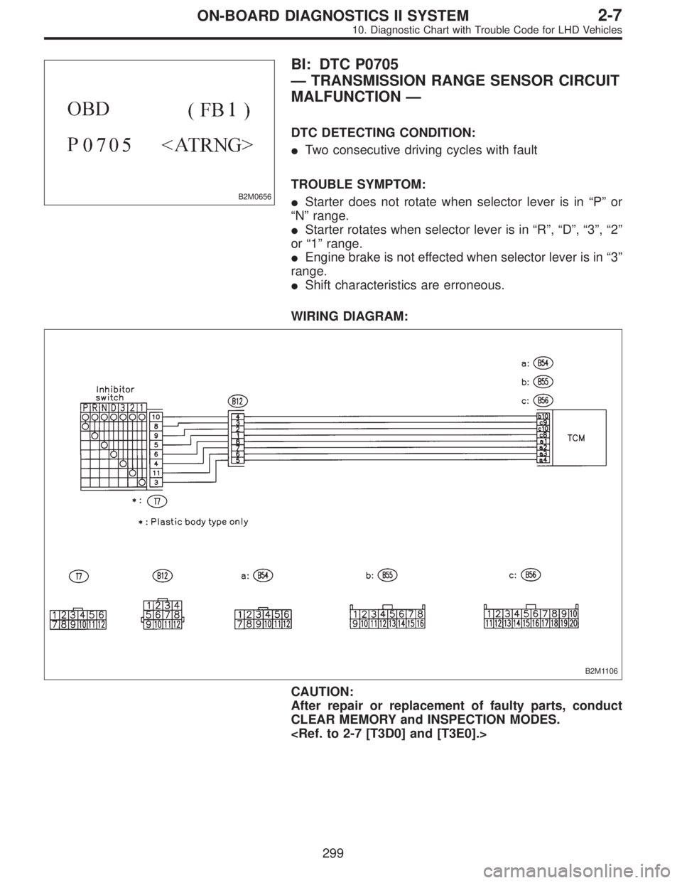
BI: DTC P0705
—TRANSMISSION RANGE SENSOR CIRCUIT
MALFUNCTION—
DTC DETECTING CONDITION:
�Two consecutive driving cycles with fault
TROUBLE SYMPTOM:
�Starter does not rotate when selector lever is in“P”or
“N”range.
�Starter rotates when selector lever is in“R”,“D”,“3”,“2”
or“1”range.
�Engine brake is not effected when selector lever is in“3”
range.
�Shift characteristics are erroneous.
WIRING DIAGRAM:
B2M1106
CAUTION:
After repair or replacement of faulty parts, conduct
CLEAR MEMORY and INSPECTION MODES.
299
2-7ON-BOARD DIAGNOSTICS II SYSTEM
10. Diagnostic Chart with Trouble Code for LHD Vehicles
Page 2180 of 3342
B2M1113
BX: DTC P1100
—STARTER SWITCH CIRCUIT LOW INPUT
—
DTC DETECTING CONDITION:
�Two consecutive driving cycles with fault
TROUBLE SYMPTOM:
�Failure of engine to start
WIRING DIAGRAM:
B2M1047
CAUTION:
After repair or replacement of faulty parts, conduct
CLEAR MEMORY and INSPECTION MODES.
329
2-7ON-BOARD DIAGNOSTICS II SYSTEM
10. Diagnostic Chart with Trouble Code for LHD Vehicles
Page 2181 of 3342
10BX1CHECK OPERATION OF STARTER
MOTOR.
: Does starter motor operate when ignition
switch to“ST”?
NOTE:
�On AT vehicles, place the inhibitor switch in the“P”or“N”
position.
�On MT vehicles, depress the clutch pedal.
: Repair harness and connector.
NOTE:
In this case, repair the following:
�Open or ground short circuit in harness between ECM
and starter motor connector.
�Poor contact in ECM connector.
: Check starter motor circuit.
330
2-7ON-BOARD DIAGNOSTICS II SYSTEM
10. Diagnostic Chart with Trouble Code for LHD Vehicles
Page 2199 of 3342
B2M1122
CD: DTC P1120
—STARTER SWITCH CIRCUIT HIGH
INPUT—
DTC DETECTING CONDITION:
�Two consecutive driving cycles with fault
TROUBLE SYMPTOM:
�Failure of engine to start
WIRING DIAGRAM:
B2M1047
CAUTION:
After repair or replacement of faulty parts, conduct
CLEAR MEMORY and INSPECTION MODES.
348
2-7ON-BOARD DIAGNOSTICS II SYSTEM
10. Diagnostic Chart with Trouble Code for LHD Vehicles