Page 1281 of 3342
8. CLEARANCE TABLE (RHD MODEL)
CAUTION:
This table lists various clearances that must be cor-
rectly adjusted to ensure normal vehicle driving with-
out interfering noise, or any other faults.
LocationMinimum
allowance
mm (in)LocationMinimum
allowance
mm (in)
�
1Crossmember—Pipe5 (0.20)�5Stabilizer—Pipe5 (0.20)
�
2DOJ—Shaft or joint14 (0.55)�6Exhaust pipe—Pipe15 (0.59)
�
3DOJ—Valve housing11 (0.43)�7Exhaust pipe—Gearbox boot15 (0.59)
�
4Pipe—Pipe
2 (0.08)�
8Side frame—Hose A and B15 (0.59)
Pipe—Crossmember�9Pipe portion of hose A—Pipe portion of hose B1.5
(0.059)
B4M0676A
97
4-3DIAGNOSTICS
1. Power Steering
Page 1290 of 3342
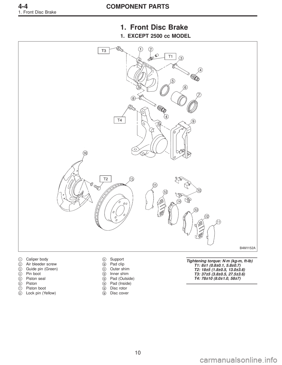
1. Front Disc Brake
1. EXCEPT 2500 cc MODEL
B4M1152A
�1Caliper body
�
2Air bleeder screw
�
3Guide pin (Green)
�
4Pin boot
�
5Piston seal
�
6Piston
�
7Piston boot
�
8Lock pin (Yellow)�
9Support
�
10Pad clip
�
11Outer shim
�
12Inner shim
�
13Pad (Outside)
�
14Pad (Inside)
�
15Disc rotor
�
16Disc cover
Tightening torque: N⋅m (kg-m, ft-lb)
T1: 8±1 (0.8±0.1, 5.8±0.7)
T2: 18±5 (1.8±0.5, 13.0±3.6)
T3: 37±5 (3.8±0.5, 27.5±3.6)
T4: 78±10 (8.0±1.0, 58±7)
10
4-4COMPONENT PARTS
1. Front Disc Brake
Page 1291 of 3342
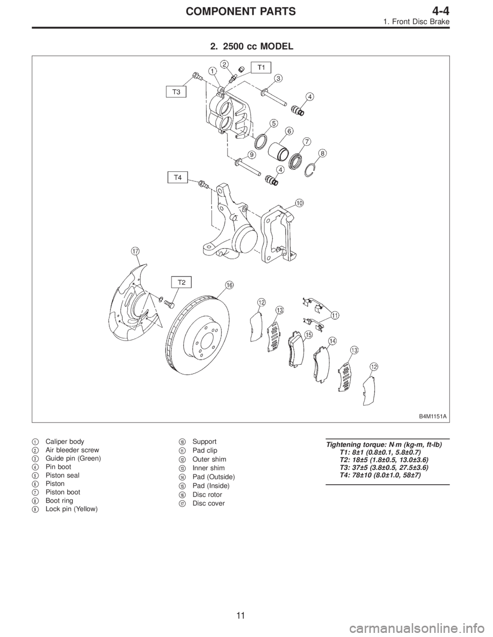
2. 2500 cc MODEL
B4M1151A
�1Caliper body
�
2Air bleeder screw
�
3Guide pin (Green)
�
4Pin boot
�
5Piston seal
�
6Piston
�
7Piston boot
�
8Boot ring
�
9Lock pin (Yellow)�
10Support
�
11Pad clip
�
12Outer shim
�
13Inner shim
�
14Pad (Outside)
�
15Pad (Inside)
�
16Disc rotor
�
17Disc cover
Tightening torque: N⋅m (kg-m, ft-lb)
T1: 8±1 (0.8±0.1, 5.8±0.7)
T2: 18±5 (1.8±0.5, 13.0±3.6)
T3: 37±5 (3.8±0.5, 27.5±3.6)
T4: 78±10 (8.0±1.0, 58±7)
11
4-4COMPONENT PARTS
1. Front Disc Brake
Page 1292 of 3342
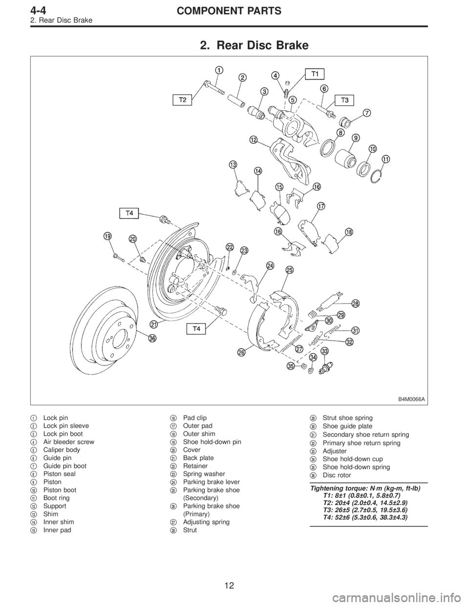
2. Rear Disc Brake
B4M0066A
�1Lock pin
�
2Lock pin sleeve
�
3Lock pin boot
�
4Air bleeder screw
�
5Caliper body
�
6Guide pin
�
7Guide pin boot
�
8Piston seal
�
9Piston
�
10Piston boot
�
11Boot ring
�
12Support
�
13Shim
�
14Inner shim
�
15Inner pad�
16Pad clip
�
17Outer pad
�
18Outer shim
�
19Shoe hold-down pin
�
20Cover
�
21Back plate
�
22Retainer
�
23Spring washer
�
24Parking brake lever
�
25Parking brake shoe
(Secondary)
�
26Parking brake shoe
(Primary)
�
27Adjusting spring
�
28Strut�
29Strut shoe spring
�
30Shoe guide plate
�
31Secondary shoe return spring
�
32Primary shoe return spring
�
33Adjuster
�
34Shoe hold-down cup
�
35Shoe hold-down spring
�
36Disc rotor
Tightening torque: N⋅m (kg-m, ft-lb)
T1: 8±1 (0.8±0.1, 5.8±0.7)
T2: 20±4 (2.0±0.4, 14.5±2.9)
T3: 26±5 (2.7±0.5, 19.5±3.6)
T4: 52±6 (5.3±0.6, 38.3±4.3)
12
4-4COMPONENT PARTS
2. Rear Disc Brake
Page 1293 of 3342
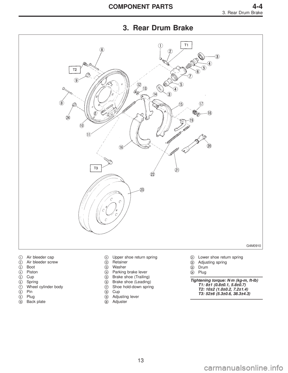
3. Rear Drum Brake
G4M0910
�1Air bleeder cap
�
2Air bleeder screw
�
3Boot
�
4Piston
�
5Cup
�
6Spring
�
7Wheel cylinder body
�
8Pin
�
9Plug
�
10Back plate�
11Upper shoe return spring
�
12Retainer
�
13Washer
�
14Parking brake lever
�
15Brake shoe (Trailing)
�
16Brake shoe (Leading)
�
17Shoe hold-down spring
�
18Cup
�
19Adjusting lever
�
20Adjuster�
21Lower shoe return spring
�
22Adjusting spring
�
23Drum
�
24Plug
Tightening torque: N⋅m (kg-m, ft-lb)
T1: 8±1 (0.8±0.1, 5.8±0.7)
T2: 10±2 (1.0±0.2, 7.2±1.4)
T3: 52±6 (5.3±0.6, 38.3±4.3)
13
4-4COMPONENT PARTS
3. Rear Drum Brake
Page 1307 of 3342
1. Front Disc Brake
B4M0065B
�1Air bleeder screw
�
2Guide pin
�
3Guide pin boot
�
4Piston
�
5Piston seal
�
6Piston boot
�
7Lock pin boot
�
8Lock pin sleeve
�
9Caliper body�
10Lock pin
�
11Housing
�
12Support
�
13Pad clip
�
14Outer shim
�
15Outer pad
�
16Inner pad
�
17Inner shim
�
18Shim�
19Disc rotor
�
20Disc cover
Tightening torque: N⋅m (kg-m, ft-lb)
T1: 8±1 (0.8±0.1, 5.8±0.7)
T2: 18±5 (1.8±0.5, 13.0±3.6)
T3: 39±5 (4±0.5, 28.9±3.6)
T4: 78±10 (8.0±1.0, 58±7)
27
4-4SERVICE PROCEDURE
1. Front Disc Brake
Page 1310 of 3342
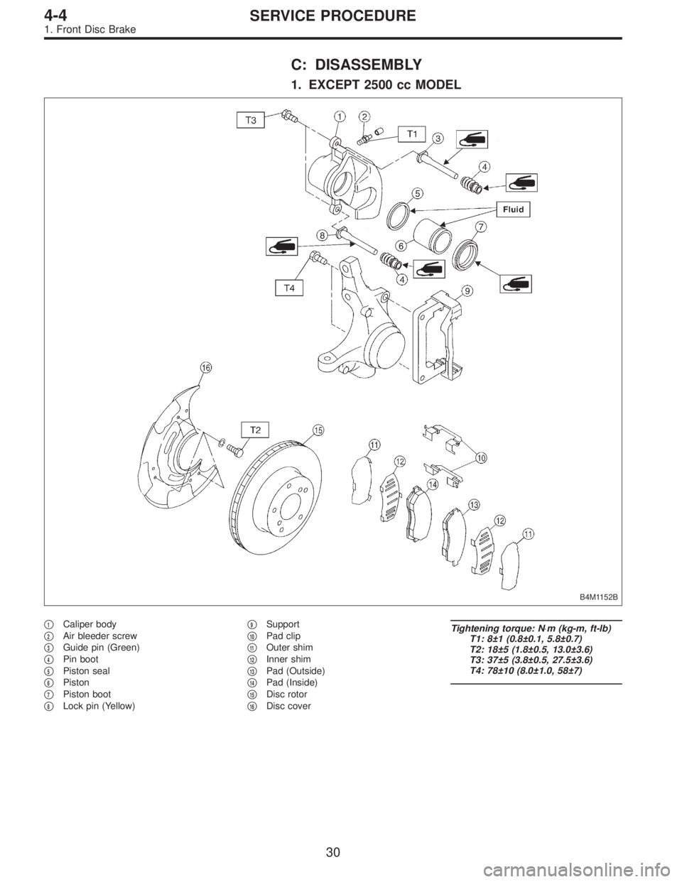
C: DISASSEMBLY
1. EXCEPT 2500 cc MODEL
B4M1152B
�1Caliper body
�
2Air bleeder screw
�
3Guide pin (Green)
�
4Pin boot
�
5Piston seal
�
6Piston
�
7Piston boot
�
8Lock pin (Yellow)�
9Support
�
10Pad clip
�
11Outer shim
�
12Inner shim
�
13Pad (Outside)
�
14Pad (Inside)
�
15Disc rotor
�
16Disc cover
Tightening torque: N⋅m (kg-m, ft-lb)
T1: 8±1 (0.8±0.1, 5.8±0.7)
T2: 18±5 (1.8±0.5, 13.0±3.6)
T3: 37±5 (3.8±0.5, 27.5±3.6)
T4: 78±10 (8.0±1.0, 58±7)
30
4-4SERVICE PROCEDURE
1. Front Disc Brake
Page 1311 of 3342
1) Clean mud and foreign particles from caliper body
assembly and support.
CAUTION:
Be careful not to allow foreign particles to enter inlet
(at brake hose connector).
B4M1174A
2) Gradually supply compressed air via caliper body brake
hose to force piston out.
CAUTION:
�Place a wooden block as shown in Figure to prevent
damage to piston.
�Do not apply excessively high-pressure.
3) Remove piston boot.
B4M1173A
4) Remove piston seal from caliper body cylinder.
5) Remove guide pin and boot from caliper body.
31
4-4SERVICE PROCEDURE
1. Front Disc Brake

CAUTION:
This table lists various clearances that must be cor-
rectly adjusted to ensure normal vehicle driving with-
out interfering noise, or any other faults.
Locatio")

 Clean mud and foreign particles from caliper body
assembly and support.
CAUTION:
Be careful not to allow foreign particles to enter inlet
(at brake hose connector).
B4M1174A
2) Gradually supply com")