Page 1326 of 3342
G4M0402
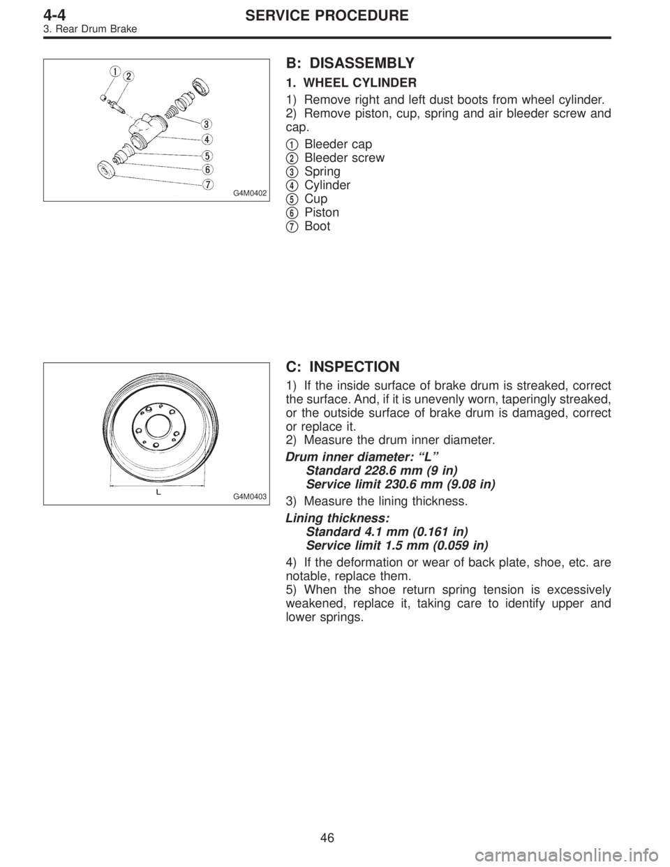
B: DISASSEMBLY
1. WHEEL CYLINDER
1) Remove right and left dust boots from wheel cylinder.
2) Remove piston, cup, spring and air bleeder screw and
cap.
�
1Bleeder cap
�
2Bleeder screw
�
3Spring
�
4Cylinder
�
5Cup
�
6Piston
�
7Boot
G4M0403
C: INSPECTION
1) If the inside surface of brake drum is streaked, correct
the surface. And, if it is unevenly worn, taperingly streaked,
or the outside surface of brake drum is damaged, correct
or replace it.
2) Measure the drum inner diameter.
Drum inner diameter: “L”
Standard 228.6 mm (9 in)
Service limit 230.6 mm (9.08 in)
3) Measure the lining thickness.
Lining thickness:
Standard 4.1 mm (0.161 in)
Service limit 1.5 mm (0.059 in)
4) If the deformation or wear of back plate, shoe, etc. are
notable, replace them.
5) When the shoe return spring tension is excessively
weakened, replace it, taking care to identify upper and
lower springs.
46
4-4SERVICE PROCEDURE
3. Rear Drum Brake
Page 1327 of 3342
 Assembly i")
D: ASSEMBLY
1. WHEEL CYLINDER
Clean all parts in brake fluid. Check and replace faulty
parts.
�Cup and boot for damage or fatigue
�Cylinder, piston and spring or damage or rust formation
1) Assembly is the reverse order of disassembly.
G4M0404
(1) When installing the cup, use ST, apply brake fluid
to the frictional surface for smooth installation and pay
attention to cup direction.
(2) STs are available in different sizes.
CAUTION:
�When replacing the repair kit, make sure that the
sizes of cylinder and cup are the same as those which
were replaced.
�Use only the tool of the correct size.
ST: ADAPTER
Applicable size Part No.
17.46 mm (11/16 in) 925460000
19.05 mm (3/4 in) 926460000
CAUTION:
While assembling, be careful to prevent any metal
chip, dust or dirt from entering the wheel cylinder.
G4M0405
2) Apply rubber grease to the boot inside as shown in
Figure.
Grease:
NIGLUBE RX-2 (Part No. 003606000)
CAUTION:
Never use brake grease.
G4M0401
E: INSTALLATION
1. WHEEL CYLINDER
Install wheel cylinder on back plate, and tighten bolts.
Tightening torque:
10±2 N⋅m (1.0±0.2 kg-m, 7.2±1.4 ft-lb)
47
4-4SERVICE PROCEDURE
3. Rear Drum Brake
Page 1343 of 3342
 Drain brake fluid from reservoir of master cylinder.
2) Remove adjusting nut and cable clamp, and disconnect
PHV cable from cable bracket on engine.
3) Detach PHV")
G4M0428
8. Hill Holder
A: REMOVAL
1) Drain brake fluid from reservoir of master cylinder.
2) Remove adjusting nut and cable clamp, and disconnect
PHV cable from cable bracket on engine.
3) Detach PHV cable from clips.
4) Remove cable clamp, and disconnect PHV cable from
PHV stay.
CAUTION:
Carefully protect boots and inner cable from damage
when disconnecting PHV cable.
5) Disconnect brake pipes from PHV.
CAUTION:
�Pay attention not to drop brake fluid onto body
painting since it may dissolve paint.
�Pay attention not to damage hexagonal head of flare
nut by using pipe wrench without fail.
6) Detach PHV along with support from side frame.
CAUTION:
Exercise utmost care to prevent foreign matter from
entering into PHV when removing it.
B: INSPECTION
Check up removed parts as follows, and replace defective
ones.
1) Check if boots of PHV cable are damaged or degraded,
and if inner cable is damaged or corroded.
2) Check if return spring is worn out, damaged or cor-
roded.
3) Confirm that rolling sound of ball is heard with PHV
inclined and lever rotates smoothly.
CAUTION:
Never disassemble PHV. Replace entire PHV assembly
if necessary.
62
4-4SERVICE PROCEDURE
8. Hill Holder
Page 1403 of 3342
B4M0628
G: INSTALLATION
1) Install hydraulic unit and bracket.
Tightening torque:
32±7 N⋅m (3.3±0.7 kg-m, 23.9±5.1 ft-lb)
2) Connect brake pipes to their correct hydraulic unit con-
nections.
3) Connect connector to hydraulic unit.
4) Install canister.
5) Install air cleaner case.
6) Install air intake duct.
7) Connect ground cable to battery.
CAUTION:
Cover relay securely with rubber boot.
21. ABS/TCS Control Module
A: REMOVAL
1) Disconnect ground cable from battery.
2) Remove floor mat located under lower right side of front
seat.
B4M0643A
3) Remove screw which secure ABS/TCS control module
from the body.
4) Disconnect connector from ABS/TCS control module.
B: INSPECTION
Check that connector is connected correctly and that con-
nector terminal sliding resistance is correct.
11 9
4-4SERVICE PROCEDURE
20. Hydraulic Unit for ABS/TCS System - 21. ABS/TCS Control Module
Page 1404 of 3342
B4M0628
G: INSTALLATION
1) Install hydraulic unit and bracket.
Tightening torque:
32±7 N⋅m (3.3±0.7 kg-m, 23.9±5.1 ft-lb)
2) Connect brake pipes to their correct hydraulic unit con-
nections.
3) Connect connector to hydraulic unit.
4) Install canister.
5) Install air cleaner case.
6) Install air intake duct.
7) Connect ground cable to battery.
CAUTION:
Cover relay securely with rubber boot.
21. ABS/TCS Control Module
A: REMOVAL
1) Disconnect ground cable from battery.
2) Remove floor mat located under lower right side of front
seat.
B4M0643A
3) Remove screw which secure ABS/TCS control module
from the body.
4) Disconnect connector from ABS/TCS control module.
B: INSPECTION
Check that connector is connected correctly and that con-
nector terminal sliding resistance is correct.
11 9
4-4SERVICE PROCEDURE
20. Hydraulic Unit for ABS/TCS System - 21. ABS/TCS Control Module
Page 1405 of 3342
C: INSTALLATION
1) Connect connector to ABS/TCS control module.
2) Install ABS/TCS control module on the body.
CAUTION:
�When installing seat rail, be careful no to have the
harness caught in the rail.
�Cover the connector completely with rubber boot.
120
4-4SERVICE PROCEDURE
21. ABS/TCS Control Module
Page 1418 of 3342
 Fluid leakage from the hydraulic mechanismRepair or replace (cup, piston seal, piston boot, master cylin")
1. Entire Brake System
Trouble and possible cause Corrective action
1. Insufficient braking
(1) Fluid leakage from the hydraulic mechanismRepair or replace (cup, piston seal, piston boot, master cylinder
piston kit, pipe or hose).
(2) Entry of air into the hydraulic mechanism Bleed the air.
(3) Excessively wide shoe clearance Adjust the clearance.
(4) Wear, deteriorated surface material, adhering water or fluid
on the liningReplace, grind or clean.
(5) Improper operation of master cylinder, disc caliper, brake
booster or check valveCorrect or replace.
2. Unstable or uneven braking
(1) Fluid on the lining, drum or rotor Eliminate cause of fluid leakage, clean, or replace.
(2) Drum or rotor eccentricity Correct or replace the drum or rotor.
(3) Worn brake drum, or damage to the drum caused by sand Correct by grinding, or replace.
(4) Improper lining contact, deteriorated surface material,
improper inferior material, or wearCorrect by grinding, or replace.
(5) Deformed back plate Correct or replace.
(6) Improper tire inflation Inflate to correct pressure.
(7) Disordered wheel alignment Adjust alignment.
(8) Loosened back plate or the support installing bolts Retighten.
(9) Loosened wheel bearing Retighten to normal tightening torque or replace.
(10) Trouble in the hydraulic system Replace the cylinder, brake pipe or hose.
(11) Uneven effect of the parking brake Check, adjust, or replace the rear brake and cable system.
3. Excessive pedal stroke
(1) Entry of air into the hydraulic mechanism Bleed the air.
(2) Excessive play in the master cylinder push rod Adjust.
(3) Fluid leakage from the hydraulic mechanismRepair or replace (cup, piston seal, piston boot, master cylinder
piston kit, pipe or hose).
(4) Improperly adjusted shoe clearance Adjust.
(5) Improper lining contact or worn lining Correct or replace.
131
4-4DIAGNOSTICS
1. Entire Brake System
Page 1434 of 3342

1) Installation is in the reverse order of removal proce-
dures.
CAUTION:
�Be careful not to bend clutch cable too much.
�Never fail t")
G4M0330
E: INSTALLATION
1. BRAKE AND CLUTCH PEDAL (2200 cc MODEL)
1) Installation is in the reverse order of removal proce-
dures.
CAUTION:
�Be careful not to bend clutch cable too much.
�Never fail to cover outer cable end with boot.
�Be careful not to kink accelerator cable.
2) Adjustment after pedal installation.
[W1A1].>
B4M0159A
2. ACCELERATOR PEDAL
1) Make sure that holder and casing cap are securely con-
nected.
�
1Casing cap
�
2Accelerator cable
�
3Toe board
�
4Accelerator pedal bracket
�
5Holder
2) Adjustment after pedal installation.
[W1A1].>
3. BRAKE AND CLUTCH PEDAL (2500 cc MODEL)
1) Set pedal bracket above steering column.
2) Insert bolts of brake booster into holes on toe board,
support it from engine room, and fit holes of pedal bracket
onto the bolts.
At this time, operating rod of brake booster should be
engaged with brake pedal.
3) While pushing pedal bracket upward firmly, tighten 4
nuts and 2 bolts at its upper surface.
B4M1189A
4) Connect operating rod of brake booster to brake pedal
using clevis pin and snap pin.
5) Connect electrical connectors for stop light switch, etc.
6) Install steering column or steering assembly as before.
7) Install nut which secures clutch master cylinder.
8) Install clevis pin which secures lever to push rod.
9) Check brake pedal free play.
10) Adjust clutch pedal.
15
4-5SERVICE PROCEDURE
1. Pedal
 Install hydraulic unit and bracket.
Tightening torque:
32±7 N⋅m (3.3±0.7 kg-m, 23.9±5.1 ft-lb)
2) Connect brake pipes to their correct hydraulic unit con-
nections. <Re")
 Install hydraulic unit and bracket.
Tightening torque:
32±7 N⋅m (3.3±0.7 kg-m, 23.9±5.1 ft-lb)
2) Connect brake pipes to their correct hydraulic unit con-
nections. <Re")