Page 2399 of 3342
B2M1142
CU: DTC P1540
—VEHICLE SPEED SENSOR MALFUNCTION
2—
WIRING DIAGRAM:
B2M1285
NOTE:
Check vehicle speed sensor 2 circuit.
548
2-7ON-BOARD DIAGNOSTICS II SYSTEM
11. Diagnostic Chart with Trouble Code for RHD Vehicles
Page 2400 of 3342
OBD0501
CV: DTC P1700
—THROTTLE POSITION SENSOR CIRCUIT
MALFUNCTION—
WIRING DIAGRAM:
B2M0613
NOTE:
Check throttle position sensor circuit for automatic trans-
mission.
549
2-7ON-BOARD DIAGNOSTICS II SYSTEM
11. Diagnostic Chart with Trouble Code for RHD Vehicles
Page 2408 of 3342
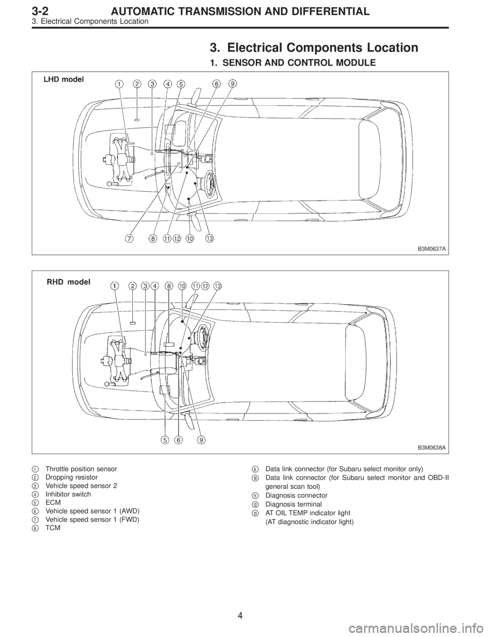
3. Electrical Components Location
1. SENSOR AND CONTROL MODULE
B3M0637A
B3M0638A
�1Throttle position sensor
�
2Dropping resistor
�
3Vehicle speed sensor 2
�
4Inhibitor switch
�
5ECM
�
6Vehicle speed sensor 1 (AWD)
�
7Vehicle speed sensor 1 (FWD)
�
8TCM�
9Data link connector (for Subaru select monitor only)
�
10Data link connector (for Subaru select monitor and OBD-II
general scan tool)
�
11Diagnosis connector
�
12Diagnosis terminal
�
13AT OIL TEMP indicator light
(AT diagnostic indicator light)
4
3-2AUTOMATIC TRANSMISSION AND DIFFERENTIAL
3. Electrical Components Location
Page 2411 of 3342
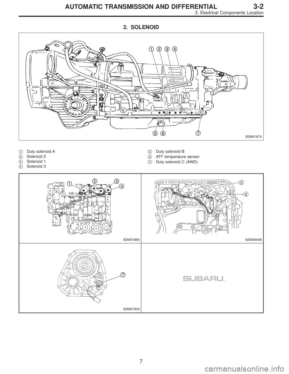
2. SOLENOID
B3M0187A
�1Duty solenoid A
�
2Solenoid 2
�
3Solenoid 1
�
4Solenoid 3�
5Duty solenoid B
�
6ATF temperature sensor
�
7Duty solenoid C (AWD)
B3M0188AB2M0464B
B3M0190A
7
3-2AUTOMATIC TRANSMISSION AND DIFFERENTIAL
3. Electrical Components Location
Page 2412 of 3342
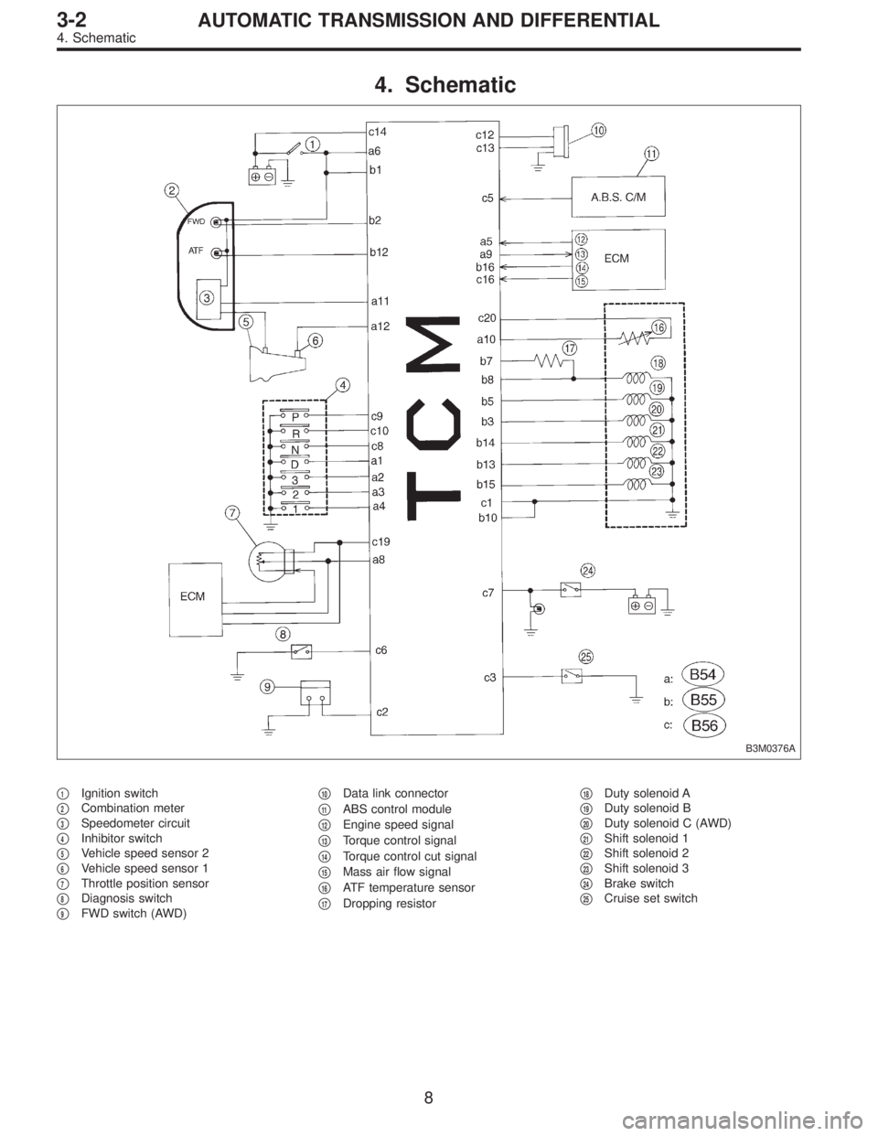
4. Schematic
B3M0376A
�1Ignition switch
�
2Combination meter
�
3Speedometer circuit
�
4Inhibitor switch
�
5Vehicle speed sensor 2
�
6Vehicle speed sensor 1
�
7Throttle position sensor
�
8Diagnosis switch
�
9FWD switch (AWD)�
10Data link connector
�
11ABS control module
�
12Engine speed signal
�
13Torque control signal
�
14Torque control cut signal
�
15Mass air flow signal
�
16ATF temperature sensor
�
17Dropping resistor�
18Duty solenoid A
�
19Duty solenoid B
�
20Duty solenoid C (AWD)
�
21Shift solenoid 1
�
22Shift solenoid 2
�
23Shift solenoid 3
�
24Brake switch
�
25Cruise set switch
8
3-2AUTOMATIC TRANSMISSION AND DIFFERENTIAL
4. Schematic
Page 2414 of 3342
Resistance to
body
(ohms)
Throttle position
sensorB54 8Throttle fully closed. 0.5±0.2
—
Throttle fully open. 4.6±0.3
Throttle positio")
ContentConnector
No.Terminal
No.Measuring conditionsVoltage
(V)Resistance to
body
(ohms)
Throttle position
sensorB54 8Throttle fully closed. 0.5±0.2
—
Throttle fully open. 4.6±0.3
Throttle position
sensor power
supplyB56 19Ignition switch ON
(With engine OFF)5.05±0.25—
ATF temperature
sensorB54 10ATF temperature 20°C(68°F) 3.45±0.55 2.1—2.9 k
ATF temperature 80°C (176°F) 1.2±0.2 275—375
Vehicle speed
sensor 1B54 12Vehicle stopped. 0
450—720
Vehicle speed at least 20 km/h (12
MPH)More than 1 (AC range)
Vehicle speed
sensor 2B56 11When vehicle is slowly moved at
least 2 meters (7ft).Less than 1)More than 9—
Engine speed
signalB54 5Ignition switch ON (with engine
OFF).More than 10.5
—
Ignition switch ON (with engine ON). 8—11
Cruise set signal B56 3When cruise control is set (SET
lamp ON).Less than 1
—
When cruise control is not set (SET
lamp OFF).More than 6.5
Torque control
signalB55 16 Ignition switch ON 5±1—
Torque control cut
signalB56 16 Ignition switch ON 6—9—
Mass air flow
signalB54 9 Engine idling after warm-up 0.5—1.2—
Shift solenoid 1 B55 141st or 4th gear More than 9
20—32
2nd or 3rd gear Less than 1
Shift solenoid 2 B55 131st or 2nd gear More than 9
20—32
3rd or 4th gear Less than 1
Shift solenoid 3 B55 15Select lever in“N”range (with
throttle fully closed).Less than 1
20—32
Select lever in“D”range (with
throttle fully closed).More than 9
Duty solenoid A B55 8Throttle fully closed (with engine
OFF) after warm-up.1.5—4.0
2.0—4.5
Throttle fully open (with engine
OFF) after warm-up.Less than 1
Dropping resistor B55 7Throttle fully closed (with engine
OFF) after warm-up.More than 8.5
12—18
Throttle fully open (with engine
OFF) after warm-up.Less than 1
Duty solenoid B B55 5When lock up occurs. More than 8.5
9—17
When lock up is released. Less than 0.5
Duty solenoid C
(AWD model only)B55 3Fuse on FWD switch More than 8.5
9—17 Fuse removed from FWD switch
(with throttle fully open and with
select lever in 1st gear).Less than 0.5
Sensor ground
line 1B54 7—0 Less than 1
Sensor ground
line 2B56 20—0 Less than 1
System ground
lineB56 1—0 Less than 1
Power system
ground lineB55 10—0 Less than 1
FWD switch
(AWD model only)B56 2Fuse removed. 6—9.1
—
Fuse installed. Less than 1
10
3-2AUTOMATIC TRANSMISSION AND DIFFERENTIAL
5. Transmission Control Module (TCM) I/O Signal
Page 2416 of 3342
B: ABNORMAL DISPLAY ON AT OIL TEMP
INDICATOR
When any on-board diagnostic item is malfunctioning, the
display on the AT OIL TEMP indicator blinks immediately
after the engine starts.
The malfunctioning part or unit can be determined by a
trouble code during on-board diagnostic operation. Prob-
lems which occurred previously can also be identified
through the memory function.
If the AT OIL TEMP indicator does not show a problem
(although a problem is occurring), the problem can be
determined by checking the performance characteristics of
each sensor using the select monitor.
Indicator signal is as shown in the figure.
WARNING:
Warning can be noticed only when the engine is ini-
tially started.
B3M0410A
12
3-2AUTOMATIC TRANSMISSION AND DIFFERENTIAL
6. Diagnostic Chart for On-board Diagnostic System
Page 2418 of 3342
Page
11 Duty solenoid ADetects open or shorted drive
circuit, as well as valve seizure.PLDTY 16
12 D")
D: LIST OF TROUBLE CODE
1. TROUBLE CODE
Trouble code Item Content of diagnosisAbbr.
(Select monitor)Page
11 Duty solenoid ADetects open or shorted drive
circuit, as well as valve seizure.PLDTY 16
12 Duty solenoid BDetects open or shorted drive
circuit, as well as valve seizure.LUDTY 20
13 Shift solenoid 3Detects open or shorted drive
circuit, as well as valve seizure.OVR 24
14 Shift solenoid 2Detects open or shorted drive
circuit, as well as valve seizure.SFT2 26
15 Shift solenoid 1Detects open or shorted drive
circuit, as well as valve seizure.SFT1 28
21 ATF temperature sensorDetects open or shorted input
signal circuit.ATFT 30
22 Mass air flow signalDetects open or shorted input
signal circuit.AFM 33
23 Engine speed signalDetects open or shorted input
signal circuit.EREV 35
24 Duty solenoid CDetects open or shorted drive
circuit, as well as valve seizure.4WDTY 37
25 Torque control signalDetects open or shorted input
signal circuit.TQ.CT 39
31 Throttle position sensorDetects open or shorted input
signal circuit.THV 41
32 Vehicle speed sensor 1Detects open or shorted input
signal circuit.VSP1 44
33 Vehicle speed sensor 2Detects open or shorted input
signal circuit.VSP2 48
14
3-2AUTOMATIC TRANSMISSION AND DIFFERENTIAL
6. Diagnostic Chart for On-board Diagnostic System
![SUBARU LEGACY 1997 Service Repair Manual B2M1142
CU: DTC P1540
—VEHICLE SPEED SENSOR MALFUNCTION
2—
WIRING DIAGRAM:
B2M1285
NOTE:
Check vehicle speed sensor 2 circuit.
<Ref. to 2-7 [T10CX0].>
548
2-7ON-BOARD DIAGNOSTICS II SYSTEM
11. Dia](/manual-img/17/57434/w960_57434-2398.png "SUBARU LEGACY 1997 Service Repair Manual B2M1142
CU: DTC P1540
—VEHICLE SPEED SENSOR MALFUNCTION
2—
WIRING DIAGRAM:
B2M1285
NOTE:
Check vehicle speed sensor 2 circuit.
<Ref. to 2-7 [T10CX0].>
548
2-7ON-BOARD DIAGNOSTICS II SYSTEM
11. Dia")
![SUBARU LEGACY 1997 Service Repair Manual OBD0501
CV: DTC P1700
—THROTTLE POSITION SENSOR CIRCUIT
MALFUNCTION—
WIRING DIAGRAM:
B2M0613
NOTE:
Check throttle position sensor circuit for automatic trans-
mission.
<Ref. to 2-7 [T10CY0].>
549](/manual-img/17/57434/w960_57434-2399.png "SUBARU LEGACY 1997 Service Repair Manual OBD0501
CV: DTC P1700
—THROTTLE POSITION SENSOR CIRCUIT
MALFUNCTION—
WIRING DIAGRAM:
B2M0613
NOTE:
Check throttle position sensor circuit for automatic trans-
mission.
<Ref. to 2-7 [T10CY0].>
549")