Page 2422 of 3342

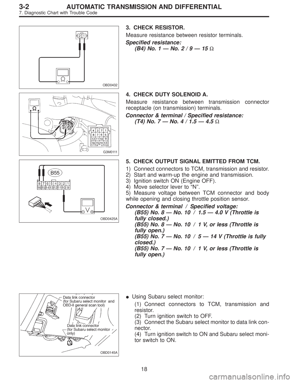
OBD0432
3. CHECK RESISTOR.
Measure resistance between resistor terminals.
Specified resistance:
(B4) No. 1—No.2/9—15Ω
G3M0111
4. CHECK DUTY SOLENOID A.
Measure resistance between transmission connector
receptacle (on transmission) terminals.
Connector & terminal / Specified resistance:
(T4) No. 7—No. 4 / 1.5—4.5Ω
OBD0425A
5. CHECK OUTPUT SIGNAL EMITTED FROM TCM.
1) Connect connectors to TCM, transmission and resistor.
2) Start and warm-up the engine and transmission.
3) Ignition switch ON (Engine OFF).
4) Move selector lever to“N”.
5) Measure voltage between TCM connector and body
while opening and closing throttle position sensor.
Connector & terminal / Specified voltage:
(B55) No. 8—No. 10 / 1.5—4.0 V (Throttle is
fully closed.)
(B55) No. 8—No. 10 / 1 V, or less (Throttle is
fully open.)
(B55) No. 7—No. 10 / 5—14 V (Throttle is fully
closed.)
(B55) No. 7—No. 10 / 1 V, or less (Throttle is
fully open.)
OBD0145A
�Using Subaru select monitor:
(1) Connect connectors to TCM, transmission and
resistor.
(2) Turn ignition switch to OFF.
(3) Connect the Subaru select monitor to data link con-
nector.
(4) Turn ignition switch to ON and Subaru select moni-
tor switch to ON.
18
3-2AUTOMATIC TRANSMISSION AND DIFFERENTIAL
7. Diagnostic Chart with Trouble Code
Page 2434 of 3342
F: TROUBLE CODE 21
—ATF TEMPERATURE SENSOR—
DIAGNOSIS:
Input signal circuit of TCM to ATF temperature sensor is
open or shorted.
TROUBLE SYMPTOM:
Excessive shift shock
1. Check harness and connectors between TCM
and ATF temperature sensor.
OK
�Not OK
Repair or replace harness connectors.
2. Check ATF temperature sensor.
OK
�Not OK
Replace ATF temperature sensor.
3. Check input signal for TCM.
Not OK
�OK
�Repair TCM connector terminal poor contact.
�Repair TCM connector terminal poor contact.
�Replace TCM.
B3M0411
�
�
�
30
3-2AUTOMATIC TRANSMISSION AND DIFFERENTIAL
7. Diagnostic Chart with Trouble Code
Page 2435 of 3342

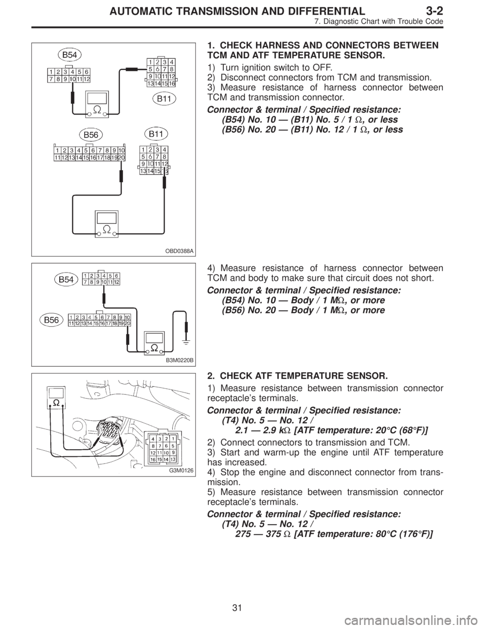
OBD0388A
1. CHECK HARNESS AND CONNECTORS BETWEEN
TCM AND ATF TEMPERATURE SENSOR.
1) Turn ignition switch to OFF.
2) Disconnect connectors from TCM and transmission.
3) Measure resistance of harness connector between
TCM and transmission connector.
Connector & terminal / Specified resistance:
(B54) No. 10—(B11)No.5/1Ω, or less
(B56) No. 20—(B11) No. 12 / 1Ω, or less
B3M0220B
4) Measure resistance of harness connector between
TCM and body to make sure that circuit does not short.
Connector & terminal / Specified resistance:
(B54) No. 10—Body/1MΩ, or more
(B56) No. 20—Body/1MΩ, or more
G3M0126
2. CHECK ATF TEMPERATURE SENSOR.
1) Measure resistance between transmission connector
receptacle’s terminals.
Connector & terminal / Specified resistance:
(T4) No. 5—No. 12 /
2.1—2.9 kΩ[ATF temperature: 20°C (68°F)]
2) Connect connectors to transmission and TCM.
3) Start and warm-up the engine until ATF temperature
has increased.
4) Stop the engine and disconnect connector from trans-
mission.
5) Measure resistance between transmission connector
receptacle’s terminals.
Connector & terminal / Specified resistance:
(T4) No. 5—No. 12 /
275—375Ω[ATF temperature: 80°C (176°F)]
31
3-2AUTOMATIC TRANSMISSION AND DIFFERENTIAL
7. Diagnostic Chart with Trouble Code
Page 2437 of 3342
G: TROUBLE CODE 22
—MASS AIR FLOW SIGNAL—
DIAGNOSIS:
Input signal circuit of TCM from ECM is open or shorted.
1. Check trouble code on engine side.
[T10B0], [T11B0].>
OK
�Not OK
Check for cause of trouble in engine.
2. Check harness connector between TCM and
ECM.
OK
�Not OK
Repair TCM connector terminal poor contact.
3. Check input signal for TCM.
OK
�Not OK
�Replace TCM.
Clear memory,Confirmation test,Not OK,
Repair TCM connector terminal poor contact.
B3M0475
1. CHECK TROUBLE CODE ON ENGINE SIDE.
Using Subaru select monitor or OBD-general scan tool,
check trouble code of mass air flow sensor on engine side.
�
�
�
33
3-2AUTOMATIC TRANSMISSION AND DIFFERENTIAL
7. Diagnostic Chart with Trouble Code
Page 2445 of 3342
K: TROUBLE CODE 31
—THROTTLE POSITION SENSOR—
DIAGNOSIS:
Input signal circuit of throttle position sensor is open or
shorted.
TROUBLE SYMPTOM:
Shift point too high or too low; engine brake not effected in
“3”range; excessive shift shock; excessive tight corner
“braking”
1. Check harness connector between TCM and
throttle position sensor.
OK
�Not OK
Repair or replace harness connectors.
2. Check throttle position sensor.
OK
�Not OK
Replace throttle position sensor.
3. Check input signal for TCM.
Not OK
�OK
�Repair TCM connector terminal poor contact.
�Replace TCM.
4. Check power supply to throttle position
sensor.
OK
�Not OK
Repair or replace harness connectors.
�Repair TCM connector terminal poor contact.
�Replace TCM.
B2M0613
�
�
�
�
41
3-2AUTOMATIC TRANSMISSION AND DIFFERENTIAL
7. Diagnostic Chart with Trouble Code
Page 2446 of 3342

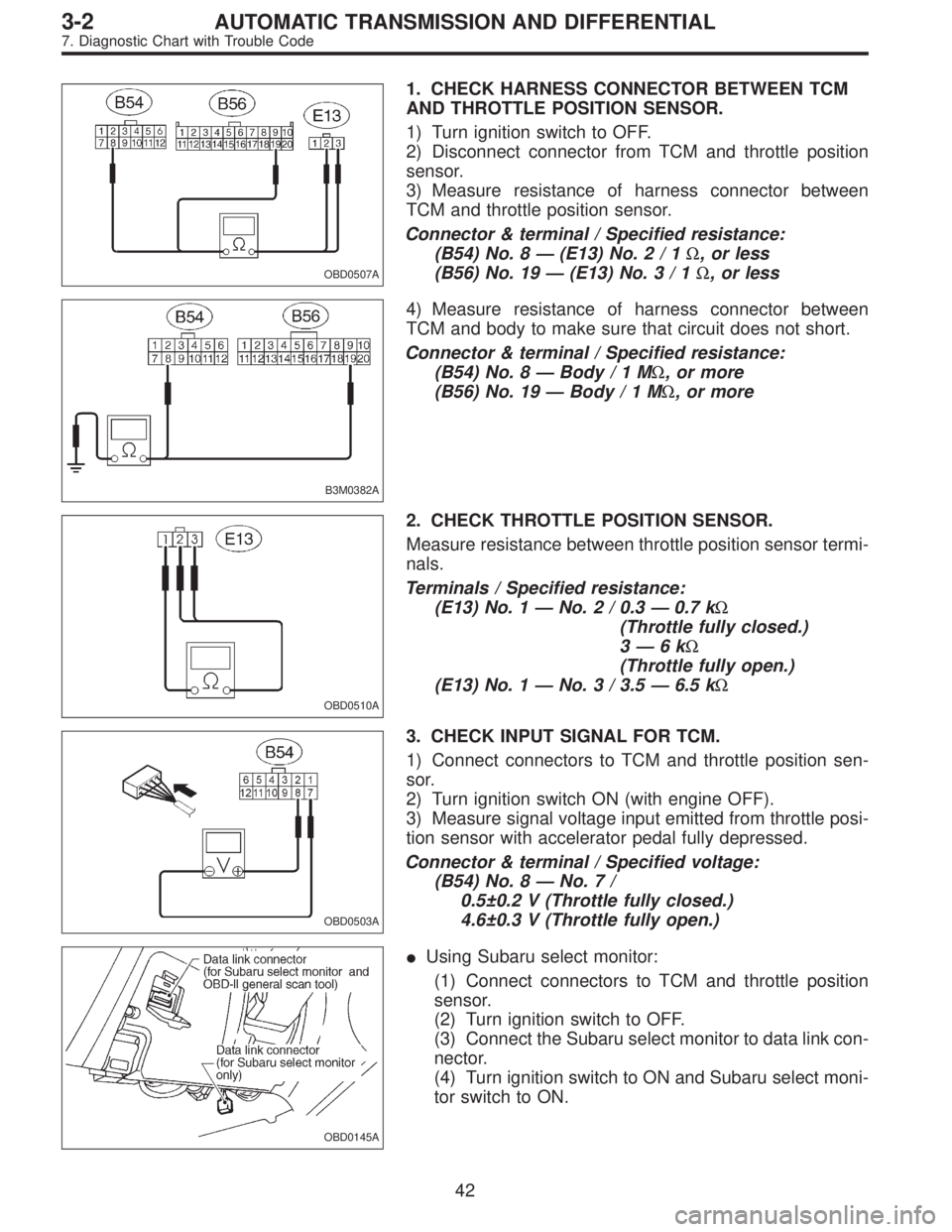
OBD0507A
1. CHECK HARNESS CONNECTOR BETWEEN TCM
AND THROTTLE POSITION SENSOR.
1) Turn ignition switch to OFF.
2) Disconnect connector from TCM and throttle position
sensor.
3) Measure resistance of harness connector between
TCM and throttle position sensor.
Connector & terminal / Specified resistance:
(B54) No. 8—(E13) No.2/1Ω, or less
(B56) No. 19—(E13) No.3/1Ω, or less
B3M0382A
4) Measure resistance of harness connector between
TCM and body to make sure that circuit does not short.
Connector & terminal / Specified resistance:
(B54) No. 8—Body/1MΩ, or more
(B56) No. 19—Body/1MΩ, or more
OBD0510A
2. CHECK THROTTLE POSITION SENSOR.
Measure resistance between throttle position sensor termi-
nals.
Terminals / Specified resistance:
(E13) No. 1—No. 2 / 0.3—0.7 kΩ
(Throttle fully closed.)
3—6kΩ
(Throttle fully open.)
(E13) No. 1—No. 3 / 3.5—6.5 kΩ
OBD0503A
3. CHECK INPUT SIGNAL FOR TCM.
1) Connect connectors to TCM and throttle position sen-
sor.
2) Turn ignition switch ON (with engine OFF).
3) Measure signal voltage input emitted from throttle posi-
tion sensor with accelerator pedal fully depressed.
Connector & terminal / Specified voltage:
(B54) No. 8—No.7/
0.5±0.2 V (Throttle fully closed.)
4.6±0.3 V (Throttle fully open.)
OBD0145A
�Using Subaru select monitor:
(1) Connect connectors to TCM and throttle position
sensor.
(2) Turn ignition switch to OFF.
(3) Connect the Subaru select monitor to data link con-
nector.
(4) Turn ignition switch to ON and Subaru select moni-
tor switch to ON.
42
3-2AUTOMATIC TRANSMISSION AND DIFFERENTIAL
7. Diagnostic Chart with Trouble Code
Page 2447 of 3342

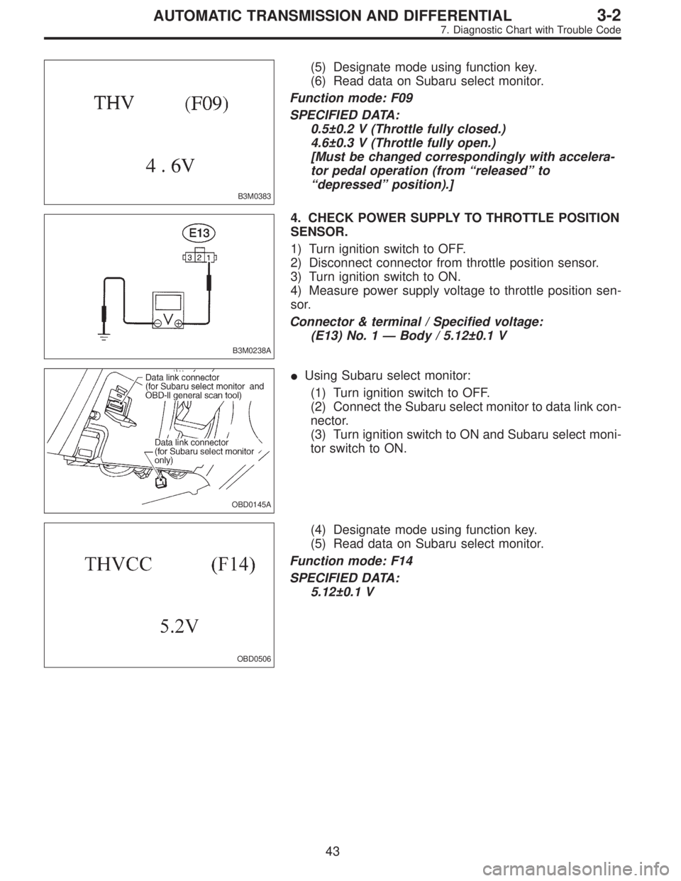
B3M0383
(5) Designate mode using function key.
(6) Read data on Subaru select monitor.
Function mode: F09
SPECIFIED DATA:
0.5±0.2 V (Throttle fully closed.)
4.6±0.3 V (Throttle fully open.)
[Must be changed correspondingly with accelera-
tor pedal operation (from“released”to
“depressed”position).]
B3M0238A
4. CHECK POWER SUPPLY TO THROTTLE POSITION
SENSOR.
1) Turn ignition switch to OFF.
2) Disconnect connector from throttle position sensor.
3) Turn ignition switch to ON.
4) Measure power supply voltage to throttle position sen-
sor.
Connector & terminal / Specified voltage:
(E13) No. 1—Body / 5.12±0.1 V
OBD0145A
�Using Subaru select monitor:
(1) Turn ignition switch to OFF.
(2) Connect the Subaru select monitor to data link con-
nector.
(3) Turn ignition switch to ON and Subaru select moni-
tor switch to ON.
OBD0506
(4) Designate mode using function key.
(5) Read data on Subaru select monitor.
Function mode: F14
SPECIFIED DATA:
5.12±0.1 V
43
3-2AUTOMATIC TRANSMISSION AND DIFFERENTIAL
7. Diagnostic Chart with Trouble Code
Page 2448 of 3342
L: TROUBLE CODE 32
—VEHICLE SPEED SENSOR 1—
DIAGNOSIS:
Input signal circuit of TCM is open or shorted.
TROUBLE SYMPTOM:
No locking-up or excessive tight corner“braking”
1. Check harness connector between TCM and
vehicle speed sensor 1.
OK
�Not OK
Repair or replace harness connectors.
2. Check vehicle speed sensor 1.
OK
�Not OK
Replace vehicle speed sensor 1.
3. Check input signal for TCM.
OK
�Not OK
�Repair TCM connector terminal poor contact.
�Replace TCM.
When trouble code 32 reappears.
Mechanical trouble between vehicle speed sensor 1
and sprocket
B3M0412
�
�
�
44
3-2AUTOMATIC TRANSMISSION AND DIFFERENTIAL
7. Diagnostic Chart with Trouble Code