Page 1924 of 3342
OBD0669A
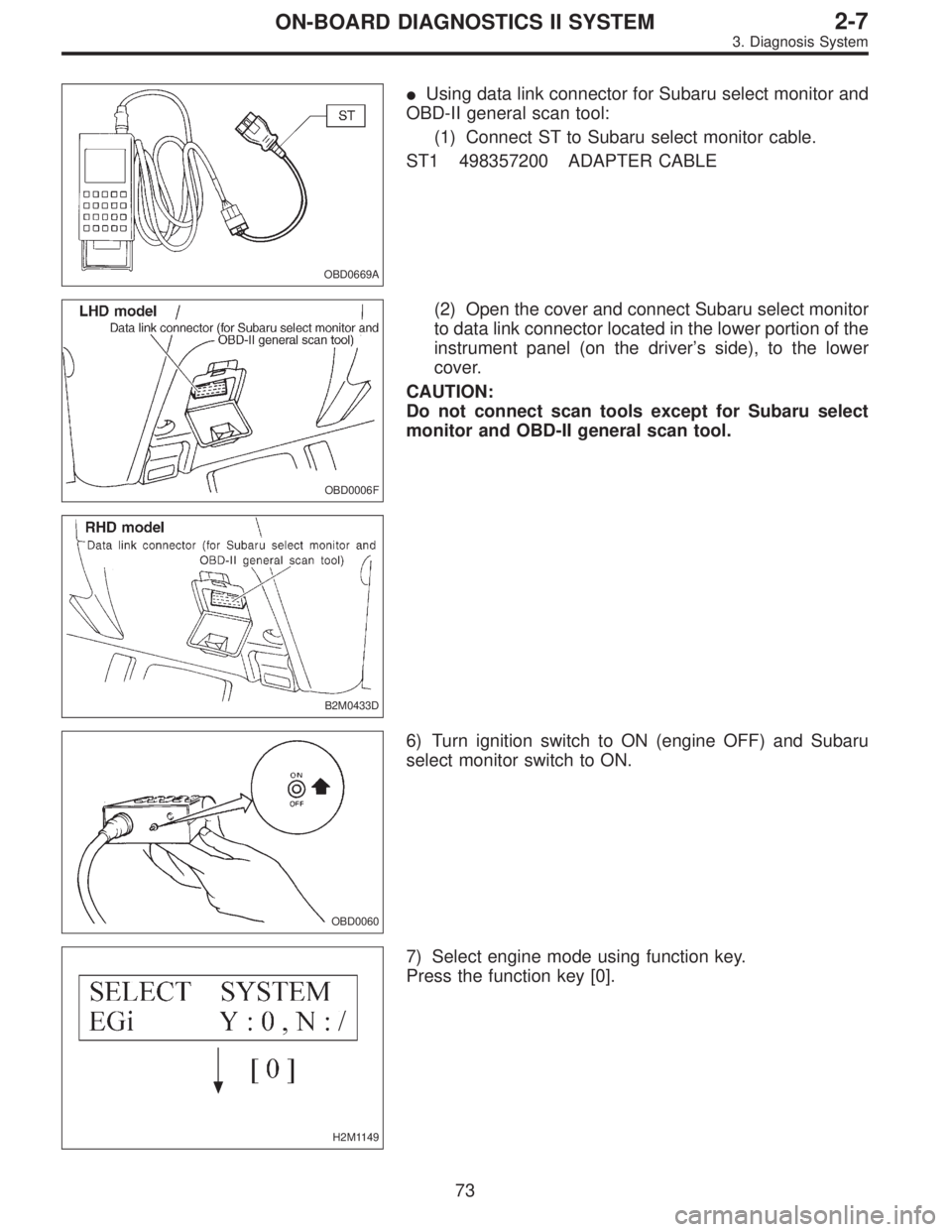
�Using data link connector for Subaru select monitor and
OBD-II general scan tool:
(1) Connect ST to Subaru select monitor cable.
ST1 498357200 ADAPTER CABLE
OBD0006F
B2M0433D
(2) Open the cover and connect Subaru select monitor
to data link connector located in the lower portion of the
instrument panel (on the driver’s side), to the lower
cover.
CAUTION:
Do not connect scan tools except for Subaru select
monitor and OBD-II general scan tool.
OBD0060
6) Turn ignition switch to ON (engine OFF) and Subaru
select monitor switch to ON.
H2M1149
7) Select engine mode using function key.
Press the function key [0].
73
2-7ON-BOARD DIAGNOSTICS II SYSTEM
3. Diagnosis System
Page 1928 of 3342
 Use engine grounding terminal or engine proper as the
grounding point to the body when measuring voltage and
resistance in the engine compartment.
OBD0040B
8) Use TCM mounting stud bolts a")
B2M0648A
7) Use engine grounding terminal or engine proper as the
grounding point to the body when measuring voltage and
resistance in the engine compartment.
OBD0040B
8) Use TCM mounting stud bolts at the body head ground-
ing point when measuring voltage and resistance inside the
passenger compartment.
9) Every MFI-related part is a precision part. Do not drop
them.
10) Observe the following cautions when installing a radio
in MFI equipped models.
CAUTION:
�The antenna must be kept as far apart as possible
from the control unit.
(The ECM is located under the steering column, inside
of the instrument panel lower trim panel.)
�The antenna feeder must be placed as far apart as
possible from the ECM and MFI harness.
�Carefully adjust the antenna for correct matching.
�When mounting a large power type radio, pay spe-
cial attention to the three items above mentioned.
�Incorrect installation of the radio may affect the
operation of the ECM.
11) Before disconnecting the fuel hose, disconnect the fuel
pump connector and crank the engine for more than five
seconds to release pressure in the fuel system. If engine
starts during this operation, run it until it stops.
12) Problems in the electronic-controlled automatic trans-
mission may be caused by failure of the engine, the elec-
tronic control system, the transmission proper, or by a com-
bination of these. These three causes must be distin-
guished clearly when performing diagnostics.
13) Diagnostics should be conducted by rotating with
simple, easy operations and proceeding to complicated,
difficult operations. The most important thing in diagnostics
is to understand the customer’s complaint, and distinguish
between the three causes.
77
2-7ON-BOARD DIAGNOSTICS II SYSTEM
4. Cautions
Page 1930 of 3342
 I/O SIGNAL
OBD0092A
ContentConnector
No.Terminal
No.Signal (V)
Note
Ignition SW ON
(Engine OFF)Engine ON (Idling)
Crankshaft
position
sensorSignal (+)")
5. Specified Data
1. ENGINE CONTROL MODULE (ECM) I/O SIGNAL
OBD0092A
ContentConnector
No.Terminal
No.Signal (V)
Note
Ignition SW ON
(Engine OFF)Engine ON (Idling)
Crankshaft
position
sensorSignal (+) B84 8 0�7—+7 Sensor output waveform
Signal (�) B84 29 0 0—
Shield B84 54 0 0—
Camshaft
position
sensorSignal (+) B84 7 0�7—+7 Sensor output waveform
Signal (�) B84 28 0 0—
Shield B84 54 0 0—
Mass air
flow sensorSignal B84 5 0—0.3 0.8—1.2—
Shield B84 57 0 0—
GND B84 53 0 0—
Throttle
position
sensorSignal B84 6Fully closed: 0.2—1.0
Fully opened: 4.2—4.7—
Power
supplyB84 21 5 5—
GND B84 20 0 0—
Front
oxygen
sensorSignal B84 23 0 0—0.9—
Shield B84 56 0 0—
Rear
oxygen
sensorSignal B84 24 0 0—0.9—
Shield B84 56 0 0—
Engine coolant
temperature sensorB84 22 1.0—1.4 1.0—1.4 After warm-up
Vehicle speed sensor 2 B84 83 0 or 5 0 or 5“5”and“0”are repeatedly
displayed when vehicle is
driven.
Starter switch B84 86 0 0 Cranking: 8 to 14
A/C switch B84 60ON: 10—13
OFF: 0ON: 13—14
OFF: 0—
Ignition switch B84 85 10—13 13—14—
Neutral position switch
(MT)
B84 82ON: 5.0±0.5
OFF: 0�On MT model; switch is ON
when gear is in neutral position.
Neutral position switch
(AT)ON: 0
OFF: 5.0±0.5�On AT model; switch is ON when
shift is in“N”or“P”position.
Test mode connector B84 84 5 5 When connected: 0
79
2-7ON-BOARD DIAGNOSTICS II SYSTEM
5. Specified Data
Page 1933 of 3342
 I/O
SIGNAL
OBD0093A
Check with ignition switch ON.
ContentConnector
No.Terminal
No.Measuring conditions Voltage (V)
Back-up power supply B56 14 Ignition switch OFF")
3. TRANSMISSION CONTROL MODULE (TCM) I/O
SIGNAL
OBD0093A
Check with ignition switch ON.
ContentConnector
No.Terminal
No.Measuring conditions Voltage (V)
Back-up power supply B56 14 Ignition switch OFF 10—16
Ignition power supplyB54 6
Ignition switch ON (with engine OFF) 10—16
B55 1
Inhibitor switch“P”range switch B56 9Selector lever in“P”range Less than 1
Selector lever in any other than“P”
rangeMore than 8
“N”range switch B56 8Selector lever in“N”range Less than 1
Selector lever in any other than“N”
rangeMore than 8
“R”range switch B56 10Selector lever in“R”range Less than 1
Selector lever in any other than“R”
rangeMore than 6
“D”range switch B54 1Selector lever in“D”range Less than 1
Selector lever in any other than“D”
rangeMore than 6
“3”range switch B54 2Selector lever in“3”range Less than 1
Selector lever in any other than“3”
rangeMore than 6
“2”range switch B54 3Selector lever in“2”range Less than 1
Selector lever in any other than“2”
rangeMore than 6
“1”range switch B54 4Selector lever in“1”range Less than 1
Selector lever in any other than“1”
rangeMore than 6
Brake switch B56 7Brake pedal depressed More than 10.5
Brake pedal released Less than 1
ABS signal B56 5ABS switch ON Less than 1
ABS switch OFF More than 6.5
AT diagnostics signal B55 12Ignition switch ON (with engine OFF) Less than 1
Ignition switch ON (with engine ON) More than 10
Diagnosis switch B56 6Diagnosis connector connected. Less than 1
Diagnosis connector disconnected. More than 6
82
2-7ON-BOARD DIAGNOSTICS II SYSTEM
5. Specified Data
Page 1935 of 3342
![SUBARU LEGACY 1997 Service Repair Manual 6. Basic Diagnostic Procedure
Trouble occurs.
Ask the customer when and how the
trouble occurred using interview
check list. <Ref. to 2-7 [T6B0].>
Start the engine.
Ye s�NoInspection using“8. Diagno](/manual-img/17/57434/w960_57434-1934.png "SUBARU LEGACY 1997 Service Repair Manual 6. Basic Diagnostic Procedure
Trouble occurs.
Ask the customer when and how the
trouble occurred using interview
check list. <Ref. to 2-7 [T6B0].>
Start the engine.
Ye s�NoInspection using“8. Diagno")
6. Basic Diagnostic Procedure
Trouble occurs.
Ask the customer when and how the
trouble occurred using interview
check list.
Start the engine.
Ye s�NoInspection using“8. Diagnostics for
Engine Start Failure”.
[T800].>
Malfunction indicator lamp (MIL) illu-
minates.
Ye s�NoInspection using“9. General Diag-
nostics Table”.
Inspection using Subaru select moni-
tor or OBD-II general scan tool.
(Subaru select monitor: MODE FB1)
Trouble code
�No trouble code designated.Repair.
See NOTE: *1
designated.
Inspection using“10. Diagnostics
Chart with Trouble Code for LHD
Vehicles”.
“11. Diagnostics Chart with Trouble
Code for RHD Vehicles”.
[T1100].>
See NOTE: *2.
�Trouble code
designated.
�
Repair.
Inspection mode
Inspection using Subaru select moni-
tor or OBD-II general scan tool.
(Subaru select monitor: MODE FB0)
No trouble code
�Clear memory mode.�
designated.
END
NOTE:
�*1: If trouble code is not shown on display although the
MIL illuminates, perform diagnostics of the MIL (CHECK
ENGINE LIGHT) circuit or combination meter.
[T700].>
�*2: Carry out the basic check, only when trouble code
about automatic transmission is shown on display.
2-7 [T6A0].>
�
�
�
�
�
�
84
2-7ON-BOARD DIAGNOSTICS II SYSTEM
6. Basic Diagnostic Procedure
Page 1942 of 3342
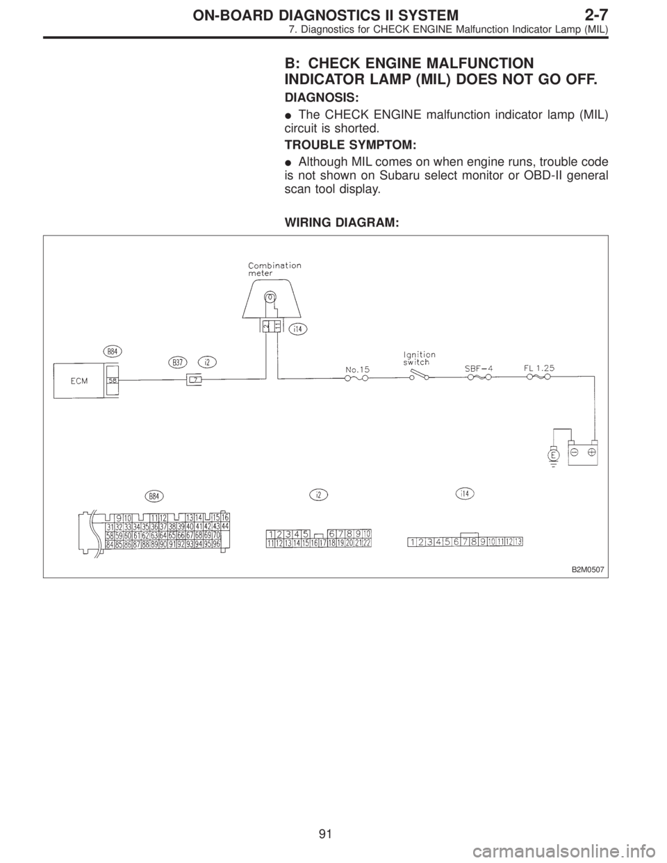
B: CHECK ENGINE MALFUNCTION
INDICATOR LAMP (MIL) DOES NOT GO OFF.
DIAGNOSIS:
�The CHECK ENGINE malfunction indicator lamp (MIL)
circuit is shorted.
TROUBLE SYMPTOM:
�Although MIL comes on when engine runs, trouble code
is not shown on Subaru select monitor or OBD-II general
scan tool display.
WIRING DIAGRAM:
B2M0507
91
2-7ON-BOARD DIAGNOSTICS II SYSTEM
7. Diagnostics for CHECK ENGINE Malfunction Indicator Lamp (MIL)
Page 1947 of 3342
8. Diagnostics for Engine Starting
Failure
A: BASIC DIAGNOSTICS CHART
Inspection of starter motor circuit.
Inspection of ECM power supply and ground line.
Inspection of ignition control system.
Inspection of fuel pump circuit.
Inspection of fuel injector circuit.
Inspection of crankshaft position sensor circuit.
Inspection of camshaft position sensor circuit.
Inspection using Subaru select monitor or OBD-II
general scan tool or inspection using“9. General
Diagnostics Table.
�
�
�
�
�
�
�
96
2-7ON-BOARD DIAGNOSTICS II SYSTEM
8. Diagnostics for Engine Starting Failure
Page 1948 of 3342
B: STARTER MOTOR CIRCUIT
WIRING DIAGRAM:
B2M1047
CAUTION:
After repair or replacement of faulty parts, conduct
CLEAR MEMORY and INSPECTION MODES.
OBD0724
8B1CHECK INPUT SIGNAL FOR STARTER
MOTOR.
1) Turn ignition switch to OFF.
2) Disconnect connector from starter motor.
3) Turn ignition switch to ST.
97
2-7ON-BOARD DIAGNOSTICS II SYSTEM
8. Diagnostics for Engine Starting Failure

![SUBARU LEGACY 1997 Service Repair Manual B: STARTER MOTOR CIRCUIT
WIRING DIAGRAM:
B2M1047
CAUTION:
After repair or replacement of faulty parts, conduct
CLEAR MEMORY and INSPECTION MODES.
<Ref. to 2-7 [T3D0] and [T3E0].>
OBD0724
8B1CHECK INPU](/manual-img/17/57434/w960_57434-1947.png "SUBARU LEGACY 1997 Service Repair Manual B: STARTER MOTOR CIRCUIT
WIRING DIAGRAM:
B2M1047
CAUTION:
After repair or replacement of faulty parts, conduct
CLEAR MEMORY and INSPECTION MODES.
<Ref. to 2-7 [T3D0] and [T3E0].>
OBD0724
8B1CHECK INPU")