Page 1877 of 3342
B: TRANSMISSION
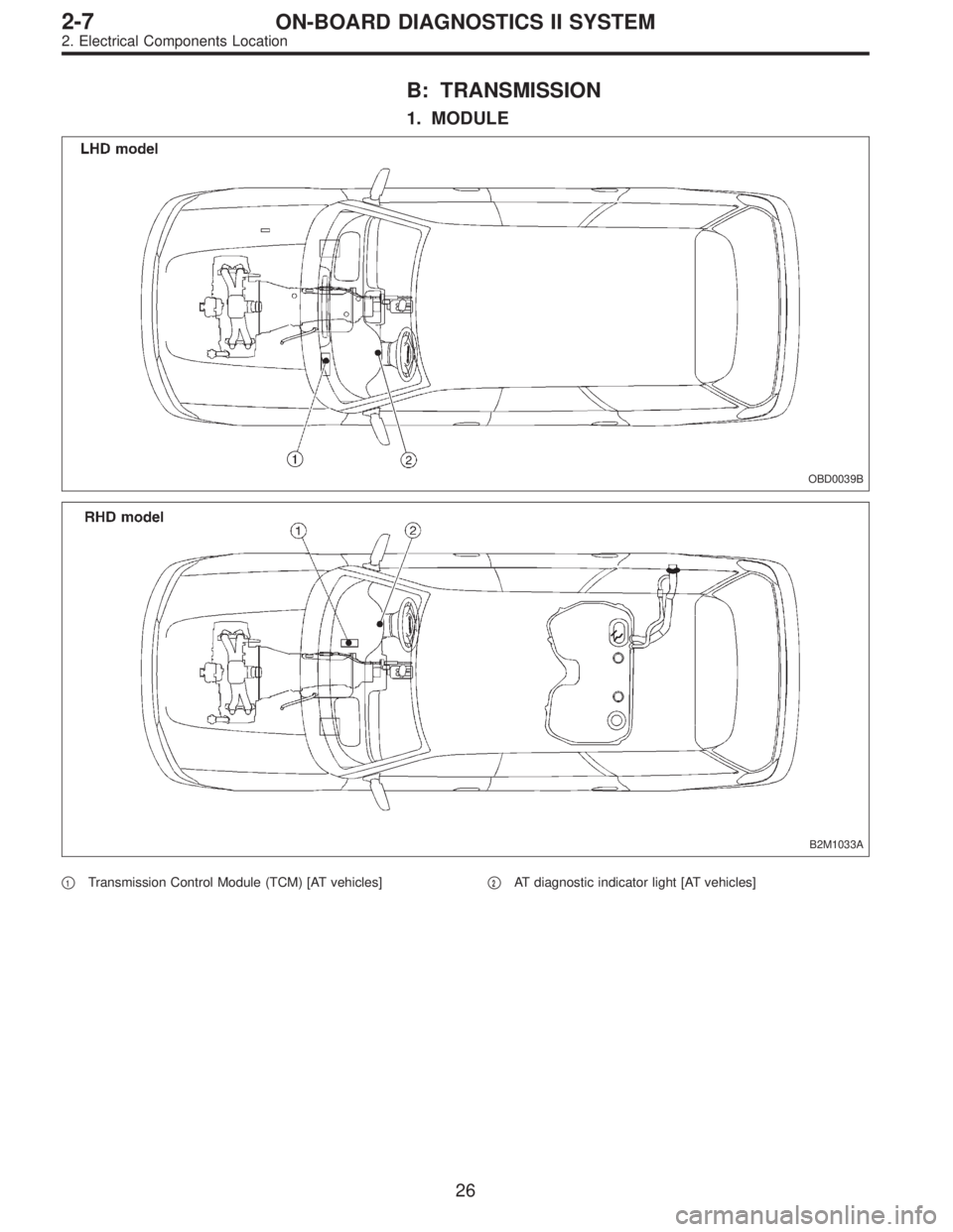
1. MODULE
OBD0039B
B2M1033A
�1Transmission Control Module (TCM) [AT vehicles]�2AT diagnostic indicator light [AT vehicles]
26
2-7ON-BOARD DIAGNOSTICS II SYSTEM
2. Electrical Components Location
Page 1879 of 3342
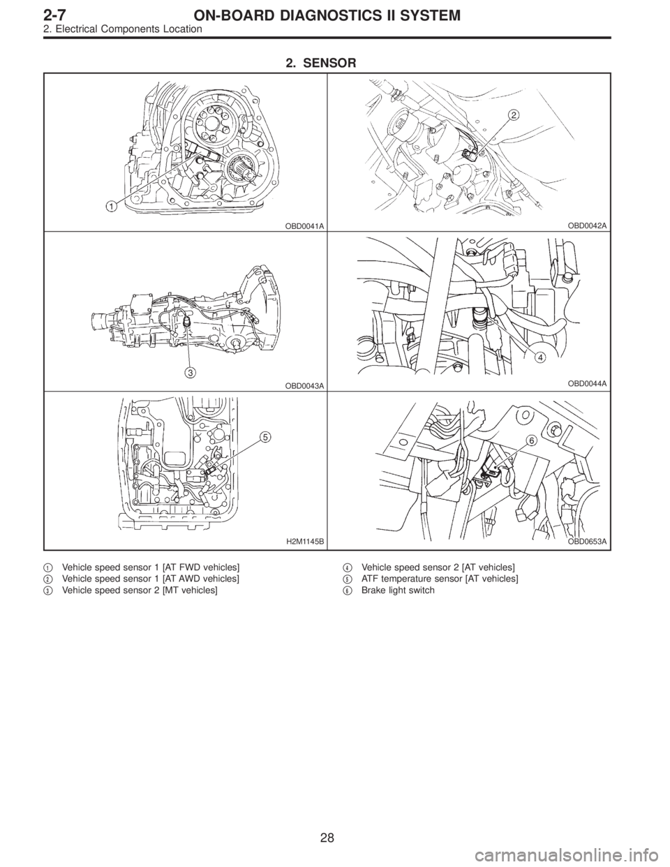
2. SENSOR
OBD0041AOBD0042A
OBD0043AOBD0044A
H2M1145BOBD0653A
�1Vehicle speed sensor 1 [AT FWD vehicles]
�
2Vehicle speed sensor 1 [AT AWD vehicles]
�
3Vehicle speed sensor 2 [MT vehicles]�
4Vehicle speed sensor 2 [AT vehicles]
�
5ATF temperature sensor [AT vehicles]
�
6Brake light switch
28
2-7ON-BOARD DIAGNOSTICS II SYSTEM
2. Electrical Components Location
Page 1880 of 3342
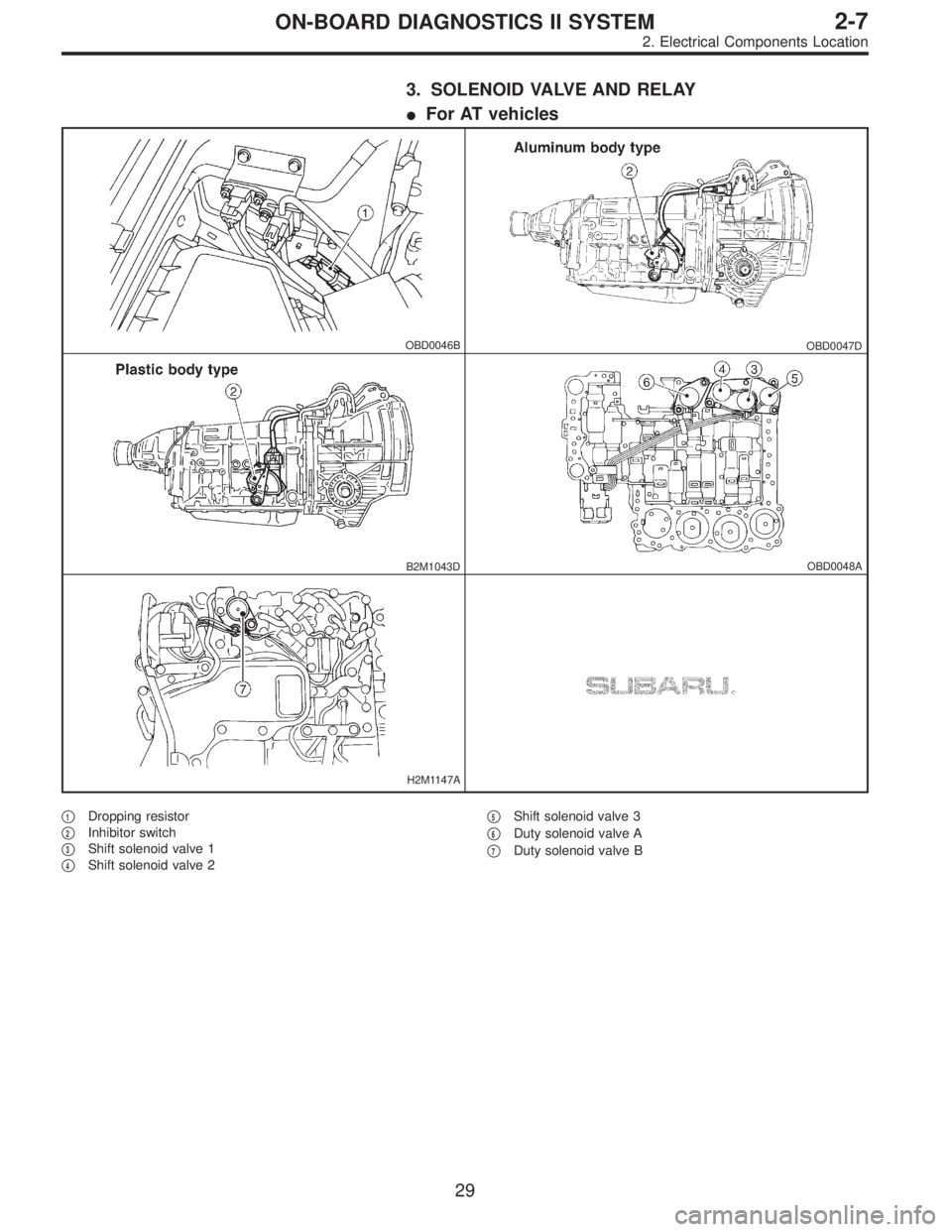
3. SOLENOID VALVE AND RELAY
�For AT vehicles
OBD0046BOBD0047D
B2M1043DOBD0048A
H2M1147A
�1Dropping resistor
�
2Inhibitor switch
�
3Shift solenoid valve 1
�
4Shift solenoid valve 2�
5Shift solenoid valve 3
�
6Duty solenoid valve A
�
7Duty solenoid valve B
29
2-7ON-BOARD DIAGNOSTICS II SYSTEM
2. Electrical Components Location
Page 1881 of 3342
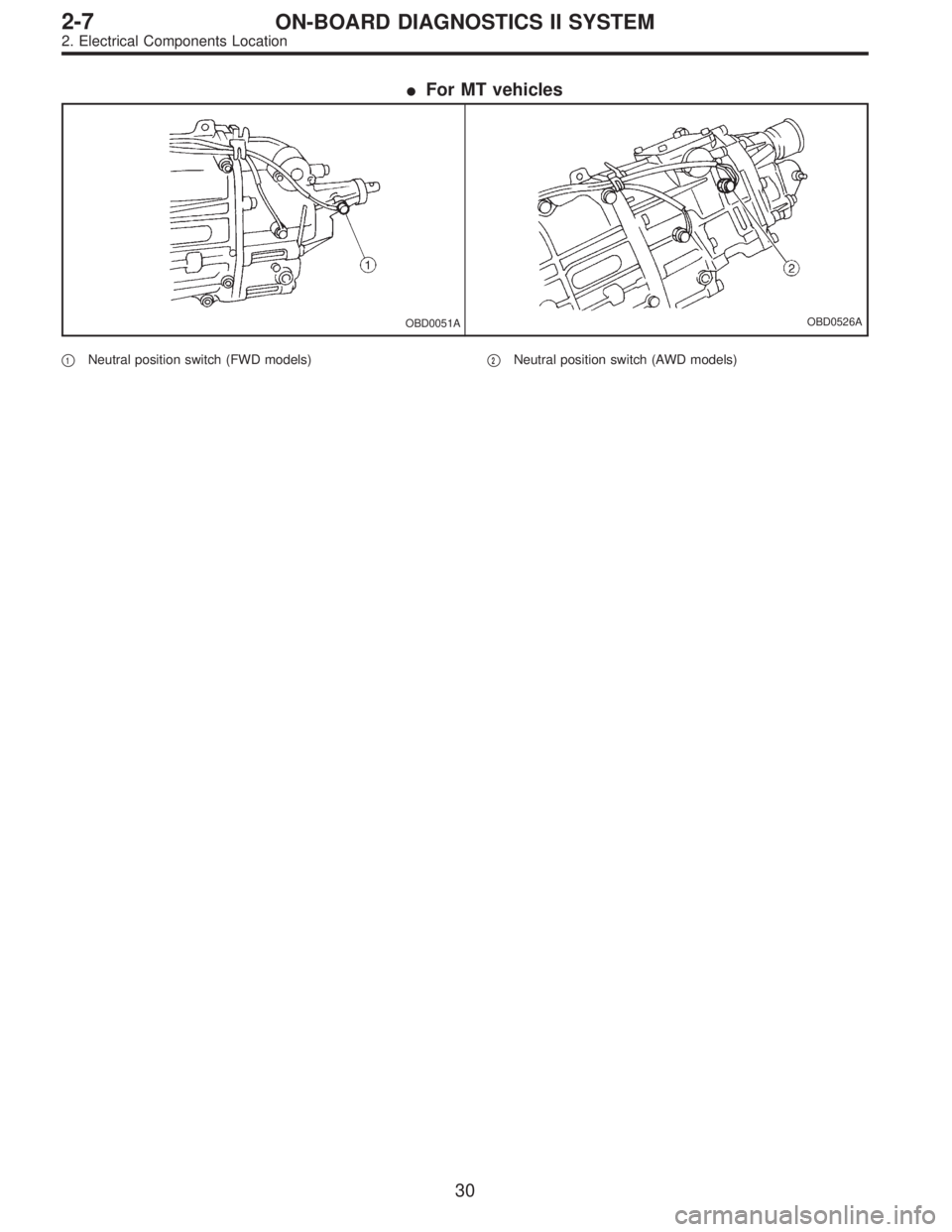
�For MT vehicles
OBD0051AOBD0526A
�1Neutral position switch (FWD models)�2Neutral position switch (AWD models)
30
2-7ON-BOARD DIAGNOSTICS II SYSTEM
2. Electrical Components Location
Page 1882 of 3342
B2M0470C
3. Diagnosis System
A: CHECK ENGINE MALFUNCTION
INDICATOR LAMP (MIL)
1. ACTIVATION OF CHECK ENGINE MALFUNCTION
INDICATOR LAMP (MIL)
1) When ignition switch is turned to ON (engine off), the
CHECK ENGINE malfunction indicator lamp (MIL) in the
combination meter illuminates.
NOTE:
If the MIL does not illuminate, perform diagnostics of the
CHECK ENGINE light circuit or the combination meter cir-
cuit.
OBD0053A
2) After starting the engine, the MIL goes out. If it does not,
either the engine or the emission control system is mal-
functioning.
OBD0054A
3) If the diagnosis system senses a misfire which could
damage the catalyzer, the MIL will blink at a cycle of 1 Hz.
OBD0055A
4) When ignition switch is turned to ON (engine off) or to
“START” with the test mode connector connected, the MIL
blinks at a cycle of 3 Hz.
31
2-7ON-BOARD DIAGNOSTICS II SYSTEM
3. Diagnosis System
Page 1883 of 3342
 Prepare a general scan tool (OBD-II general scan tool)
required by SAE J1978.
2) Open the cover and connect the")
OBD0006F
B2M0433D
B: OBD-II GENERAL SCAN TOOL
1. HOW TO USE OBD-II GENERAL SCAN TOOL
1) Prepare a general scan tool (OBD-II general scan tool)
required by SAE J1978.
2) Open the cover and connect the OBD-II general scan
tool to the data link connector located in the lower portion
of the instrument panel (on the driver’s side), to the lower
cover.
3) Using the OBD-II general scan tool, call up diagnostic
trouble code(s) and freeze frame data.
OBD-II general scan tool functions consist of:
(1) MODE $01: Current powertrain diagnostic data
(2) MODE $02: Powertrain freeze frame data
(3) MODE $03: Emission-related powertrain diagnostic
trouble codes
(4) MODE $04: Clear/Reset emission-related diagnos-
tic information
(5) MODE $05: Oxygen sensor monitoring test results
Read out data according to repair procedures.
(For detailed operation procedures, refer to the OBD-II
General Scan Tool Operation Manual.)
NOTE:
For details concerning diagnostic trouble codes, refer to
the DIAGNOSTIC TROUBLE CODE (DTC) LIST.
2-7 [T10A0], [T11A0].>
H2M1280
2. DATA LINK CONNECTOR (FOR OBD-II GENERAL
SCAN TOOL AND SUBARU SELECT MONITOR)
1) This connector is used both for OBD-II general scan
tools and the Subaru Select Monitor.
2) Terminal No. 4 to No. 6 of the data link connector is
used for the Subaru Select Monitor signal.
CAUTION:
Do not connect any scan tools other than the OBD-II
general scan tools and the Subaru Select Monitor,
because the circuit for the Subaru Select Monitor may
be damaged.
Terminal No. Contents Terminal No. Contents
1 Power supply 9 Blank
2 Blank 10 K line of ISO 9141 CARB
3 Blank 11 Blank
4Subaru Select Monitor signal (ECM to Subaru
Select Monitor)*12 Ground
5Subaru Select Monitor signal (Subaru Select
Monitor to ECM)*13 Ground
6 Subaru Select Monitor clock* 14 Blank
7 Blank 15 Blank
8 Blank 16 Blank
*: Circuit only for Subaru Select Monitor
32
2-7ON-BOARD DIAGNOSTICS II SYSTEM
3. Diagnosis System
Page 1884 of 3342

Refers to data denoting the current operating condition of
analog input/output, digital input/output and/or the power-
train system.
A list of the supp")
3. CURRENT POWERTRAIN DIAGNOSTIC DATA
(MODE $01)
Refers to data denoting the current operating condition of
analog input/output, digital input/output and/or the power-
train system.
A list of the support data and PID (Parameter Identification)
codes are shown in the following table.
PID DataUnit of measure
01 Number of emission-related powertrain trouble codes and MIL status ON/OFF
03 Fuel system control status—
04 Calculated engine load value%
05 Engine coolant temperature°C
06 Short term fuel trim%
07 Long term fuel trim%
0B Intake manifold absolute pressurekPa
0C Engine revolutionrpm
0D Vehicle speedkm/h
0E Ignition timing advance°
10 Air flow rate from mass air flow sensor g/sec
11 Throttle valve opening angle%
13 Check whether oxygen sensor is installed.—
14 Oxygen sensor output voltage and short term fuel trim associated with oxygen sensor—bank 1 V and %
15 Oxygen sensor output voltage and short term fuel trim associated with oxygen sensor—bank 2 V and %
1C On-board diagnosis system—
NOTE:
Refer to OBD-II general scan tool manufacturer’s instruc-
tion manual to access generic OBD-II PIDs (MODE $01).
33
2-7ON-BOARD DIAGNOSTICS II SYSTEM
3. Diagnosis System
Page 1885 of 3342

Refers to data denoting the operating condition when
trouble is sensed by the on-board diagnosis system.
A list of the support data and PID (Parameter Identi")
4. POWERTRAIN FREEZE FRAME DATA (MODE $02)
Refers to data denoting the operating condition when
trouble is sensed by the on-board diagnosis system.
A list of the support data and PID (Parameter Identification)
codes are shown in the following table.
PID DataUnit of measure
02 Trouble code that caused CARB required freeze frame data storage—
03 Fuel system control status—
04 Calculated engine load value%
05 Engine coolant temperature°C
06 Short term fuel trim%
07 Long term fuel trim%
0B Intake manifold absolute pressurekPa
0C Engine revolutionrpm
0D Vehicle speedkm/h
NOTE:
Refer to OBD-II general scan tool manufacturer’s instruc-
tion manual to access freeze frame data (MODE $02).
5. EMISSION-RELATED POWERTRAIN DIAGNOSTIC
TROUBLE CODE (MODE $03)
Refers to data denoting emission-related powertrain diag-
nostic trouble codes.
For details concerning diagnostic trouble codes, refer to
the DIAGNOSTIC TROUBLE CODE (DTC) LIST.
2-7 [T10A0], [T11A0].>
NOTE:
Refer to OBD-II general scan tool manufacturer’s instruc-
tion manual to access emission-related powertrain diag-
nostic trouble codes (MODE $03).
34
2-7ON-BOARD DIAGNOSTICS II SYSTEM
3. Diagnosis System

1. ACTIVATION OF CHECK ENGINE MALFUNCTION
INDICATOR LAMP (MIL)
1) When ignition switch is turned to ON (engine off), the
C")