Page 1886 of 3342

Refers to the mode used to clear or reset emission-related
diagnostic information (OBD-II trouble diagnostic informa-
tion).
NOTE:
Ref")
6. CLEAR/RESET EMISSION-RELATED DIAGNOSTIC
INFORMATION (MODE $04)
Refers to the mode used to clear or reset emission-related
diagnostic information (OBD-II trouble diagnostic informa-
tion).
NOTE:
Refer to OBD-II general scan tool manufacturer’s instruc-
tion manual to clear or reset emission-related diagnostic
information (MODE $04).
7. OXYGEN SENSOR MONITORING TEST RESULTS
(MODE $05)
Refers to the mode using oxygen sensor output data while
the on-board diagnosis system is performing diagnosis on
the oxygen sensor.
A list of the support oxygen sensor output data and test ID
(identification) are shown in the following table.
Test ID DataUnit of measure
01 Rich to lean sensor threshold voltage (constant) V
02 Lean to rich sensor threshold voltage (constant) V
03 Low sensor voltage for switch time calculation (constant) V
04 High sensor voltage for switch time calculation (constant) V
05 Rich to lean sensor switch time (calculated) sec.
06 Lean to rich sensor switch time (calculated) sec.
07 Minimum sensor voltage for test cycle (calculated) V
08 Maximum sensor voltage for test cycle (calculated) V
NOTE:
Refer to OBD-II general scan tool manufacturer’s instruc-
tion manual to access oxygen sensor monitoring test
results (MODE $05).
35
2-7ON-BOARD DIAGNOSTICS II SYSTEM
3. Diagnosis System
Page 1887 of 3342
OBD0057A
C: SUBARU SELECT MONITOR
1. HOW TO USE SUBARU SELECT MONITOR
1) Prepare Subaru select monitor and cartridge.
ST1 498307500 SELECT MONITOR KIT
ST2 498346300 CARTRIDGE
G3M0150
2) Turn ignition switch and Subaru select monitor switch to
OFF.
3) Insert cartridge into Subaru select monitor.
OBD0059B
B2M0829B
4) Connect Subaru select monitor to data link connector.
�Using data link connector for Subaru select monitor
only, connect Subaru select monitor to its data link con-
nector located in the lower portion of the instrument
panel (on the driver’s side), to the side of the center
console box.
OBD0669A
�Using data link connector for Subaru select monitor
and OBD-II general scan tool;
(1) Connect ST to Subaru select monitor cable.
ST 498357200 ADAPTER CABLE
36
2-7ON-BOARD DIAGNOSTICS II SYSTEM
3. Diagnosis System
Page 1888 of 3342
OBD0006F
B2M0433D
(2) Open the cover and connect Subaru select monitor
to data link connector located in the lower portion of the
instrument panel (on the driver’s side), to the lower
cover.
CAUTION:
Do not connect scan tools except for Subaru select
monitor and OBD-II general scan tool.
OBD0060
5) Turn ignition switch to ON (engine OFF) and Subaru
select monitor switch to ON.
6) Using Subaru select monitor, call up diagnostic trouble
code(s) and various data, then record them.
H2M1149
2. READ DIAGNOSTIC TROUBLE CODE (DTC)
SHOWN ON DISPLAY. (MODE FB1)
1) Select engine mode using function key.
Press the function key [0].
G3M0152
2) Designate mode using function key.
Press [F] [B] [1] [ENT] in that order.
37
2-7ON-BOARD DIAGNOSTICS II SYSTEM
3. Diagnosis System
Page 1889 of 3342
OBD0062
3) Ensure diagnostic trouble code(s) is shown.
(1) When there is only one diagnostic trouble code.
OBD0063
(2) When there are multiple diagnostic trouble codes.
NOTE:
For details concerning diagnostic trouble codes, refer to
the DIAGNOSTIC TROUBLE CODE (DTC) LIST.
2-7 [T10A0], [T11A0].>
H2M1149
3. READ CURRENT DATA SHOWN ON DISPLAY FOR
ENGINE. (FUNCTION MODE)
1) Select engine mode using function key.
Press the function key [0].
G3M0152
2) Designate mode using function key.
(Example: Press [F] [0] [1] [ENT] in that order.)
3) Ensure data of input or output signal is shown.
H2M1149
4. READ FREEZE FRAME DATA SHOWN ON
DISPLAY. (MODE FB2)
1) Select engine mode using function key.
Press the function key [0].
38
2-7ON-BOARD DIAGNOSTICS II SYSTEM
3. Diagnosis System
Page 1893 of 3342

6. READ DATA FUNCTION KEY LIST FOR ENGINE
Function mode Contents Abbreviation Unit of measure
F00 ROM ID number YEAR—
F01 Battery voltage VB V
F02 Vehicle speed signal VSP km/h, MPH
F03 Engine speed signal EREV rpm
F04 Engine coolant temperature signal TW°C,°F
F05 Ignition signal ADVS deg
F06 Mass air flow signal QA g/s, V
F07 Throttle position signal THV %, V
F08 Injector pulse width TIM mS
F09 Idle air control signal ISC %
F10 Load data LOAD %
F11 Front oxygen sensor output signal O2 V
F12 Front oxygen sensor maximum and minimum output signal O2max - min V, V
F13 Rear oxygen sensor output signal RO2 V
F14 Rear oxygen sensor maximum and minimum output signal RO2max - min V, V
F17 Short term fuel trim ALPHA %
F19 Knock sensor signal KNOCK deg
F20 Atmospheric absolute pressure signal BARO. P kPa, mmHg
F21 Intake manifold absolute pressure signal MANI. P kPa, mmHg
F29A/F correction coefficient [short term trim] by rear oxygen sen-
sorPHOS %
F30 Long term fuel trim [A/F learning correction coefficient] KBLRC %
F31 Long term fuel trim whole [A/F learning control coefficient] K0 %
F32 Front oxygen sensor heater current FO2H A
F33 Rear oxygen sensor heater current RO2H A
F35 Purge control solenoid valve duty ratio CPCD %
F36Maximum value of cylinder #1 misfire times during 100 rota-
tionsMF1 %
F37Maximum value of cylinder #2 misfire times during 100 rota-
tionsMF2 %
F38Maximum value of cylinder #3 misfire times during 100 rota-
tionsMF3 %
F39Maximum value of cylinder #4 misfire times during 100 rota-
tionsMF4 %
F42Maximum and minimum EGR system pressure value (AT
vehicles)EGRmax - min kPa
F43 Fuel tank pressure signal TNKP kPa, mmHg
F44 Fuel temperature signal TNKT°C,°F
F45 Fuel level signal FLEVEL V
FA 0 O N)OFF signal——
FA 1 O N)OFF signal——
FA 2 O N)OFF signal——
FA 3 O N)OFF signal——
FA 4 O N)OFF signal——
FA 5 O N)OFF signal——
FB0 Diagnostic trouble code (DTC) INSPECT—
FB1 Diagnostic trouble code (DTC) OBD—
42
2-7ON-BOARD DIAGNOSTICS II SYSTEM
3. Diagnosis System
Page 1907 of 3342
Current trouble code indicated by on-board
diagnostics after clear memo")
47. FB MODE FOR ENGINE
Function mode Abbreviation Contents Contents of display Page
FB0 INSPECT On-board diagnostics (Inspection)Current trouble code indicated by on-board
diagnostics after clear memory.65
FB1 OBD On-board diagnostics (Read data)Current trouble code indicated by on-board
diagnostics.37
FB2LOAD�F Load data
�Freeze frame data
�Data stored at the time of trouble
occurrence, is shown on display.38
TW�F Engine coolant temperature signal
ALPH�F Throttle position signal
KBLR�F Long term fuel trim
MANI�FIntake manifold absolute pressure
signal
EREV�F Engine speed signal
VSP�F Vehicle speed signal
FB3QA�F (P0100) Mass air flow signal
�Freeze frame data
�Data stored at the time of trouble
occurrence, is shown on display.40
PS�F (P0105) Pressure signal
PR�F (P0106) Pressure signal
TW�F (P0115) Engine coolant temperature signal
THV�F (P0120) Throttle position signal
EGR (P0403) EGR control solenoid valve signal
CPC (P0443) Purge control solenoid valve signal
STSW (P1100) Start switch signal
BR1 (P1102)Pressure sources switching sole-
noid valve signal
FAN1 (P1500) Radiator fan relay 1 signal
48. FC MODE FOR ENGINE
Function mode Abbreviation Contents Contents of display Page
FC0 MEMORY CLR Back-up memory clearFunction of clearing trouble code stored in
memory.64
49. FD MODE FOR ENGINE
Function mode Abbreviation Contents Contents of display Page
FD01 FUEL PUMP
Compulsory valve operation checkFunction of checking operation of fuel
pump relay, purge control solenoid valve,
radiator fan relay, A/C relay, EGR control
solenoid valve, pressure control solenoid
valve, vent control solenoid valve and pres-
sure sources switching solenoid valve.71
FD02 CPC SOL
FD03 RAD FAN
FD04 A/C RELAY
FD05 EGR SOL
FD07 PCV SOL
FD08 VENT SOL
FD10 BR SOL
NOTE:
Because ASV solenoid valve, FICD solenoid valve and air
injection system diagnosis solenoid valve are not installed,
FD06, FD09 and FD11 will be displayed but non-functional.
56
2-7ON-BOARD DIAGNOSTICS II SYSTEM
3. Diagnosis System
Page 1910 of 3342
B2M1046
52. FUNCTION MODE: F00
—MODE DISPLAY—
SPECIFIED DATA:
Data at the left should be indicated.
Probable cause (if outside“specified data”)
1. Communication failure
(No communication method can be confirmed
with power ON.)
�(1)Check loose or poor connectors, or
shortcircuit.
(2) Check type of cartridge.
2. Vehicle types cannot be identified (due to
communication failure).�Check improper cartridge.
Replace with proper one.
OBD0673
53. FUNCTION MODE: F01
—BATTERY VOLTAGE (VB)—
CONDITION:
(1) Ignition switch ON
(2) Engine idling after warm-up
SPECIFIED DATA:
(1) 12±1 V
(2) 13±1 V
1. Battery�Check battery voltage and specific gravity of
electrolyte.
2. Charging system�(1)Measure regulating voltage under no loads.
(2) Check generator (as a single unit).
59
2-7ON-BOARD DIAGNOSTICS II SYSTEM
3. Diagnosis System
Page 1911 of 3342
G3M0725
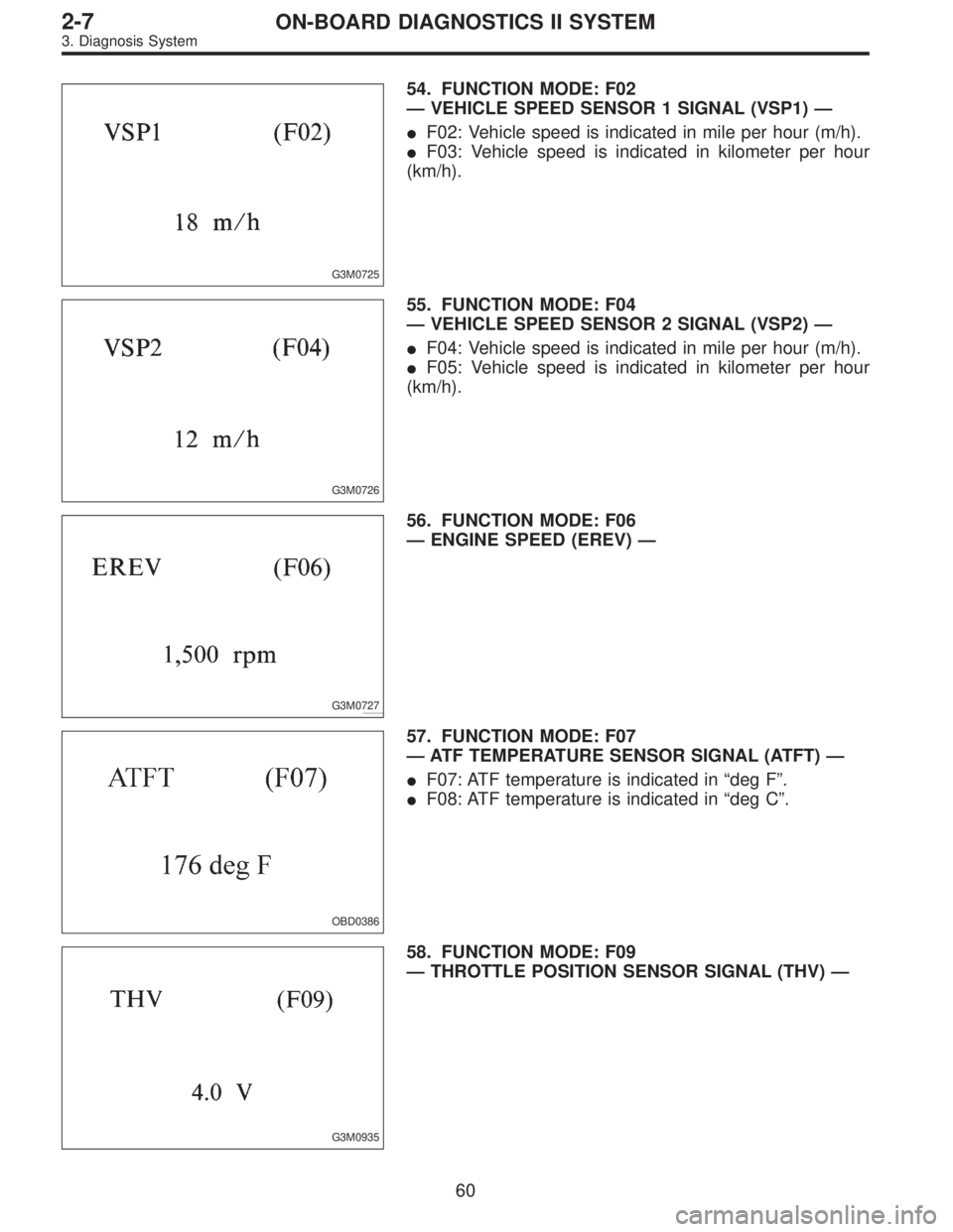
54. FUNCTION MODE: F02
—VEHICLE SPEED SENSOR 1 SIGNAL (VSP1)—
�F02: Vehicle speed is indicated in mile per hour (m/h).
�F03: Vehicle speed is indicated in kilometer per hour
(km/h).
G3M0726
55. FUNCTION MODE: F04
—VEHICLE SPEED SENSOR 2 SIGNAL (VSP2)—
�F04: Vehicle speed is indicated in mile per hour (m/h).
�F05: Vehicle speed is indicated in kilometer per hour
(km/h).
G3M0727
56. FUNCTION MODE: F06
—ENGINE SPEED (EREV)—
OBD0386
57. FUNCTION MODE: F07
—ATF TEMPERATURE SENSOR SIGNAL (ATFT)—
�F07: ATF temperature is indicated in“deg F”.
�F08: ATF temperature is indicated in“deg C”.
G3M0935
58. FUNCTION MODE: F09
—THROTTLE POSITION SENSOR SIGNAL (THV)—
60
2-7ON-BOARD DIAGNOSTICS II SYSTEM
3. Diagnosis System
 Prepare Subaru select monitor and cartridge.
ST1 498307500 SELECT MONITOR KIT
ST2 498346300 CARTRIDGE
G3M0150
2) Turn ignition")
 Open the cover and connect Subaru select monitor
to data link connector located in the lower portion of the
instrument panel (on the driver’s side), to the lower
cover.
CAUTION")
 Ensure diagnostic trouble code(s) is shown.
(1) When there is only one diagnostic trouble code.
OBD0063
(2) When there are multiple diagnostic trouble codes.
NOTE:
For details concerning di")

1. Communication failure
(No communication metho")