Page 1511 of 3342
 dia.
�
1Hood hinge front attaching hole M8
�
2Strut mount attaching hole (Front center) 9.5 mm (0.374 in)
dia")
1. ENGINE COMPARTMENT AND ROOM
B5M0187A
�0Cowl panel weather attaching hole 6 mm (0.24 in) dia.
�
1Hood hinge front attaching hole M8
�
2Strut mount attaching hole (Front center) 9.5 mm (0.374 in)
dia.
�
3Front fender attaching hole (Tip) M6
�
4Rear upper surface of front side frame 12 mm (0.47 in) dia.
�
5Middle upper surface of front side frame 20 mm (0.79 in) dia.
�
6Front side frame front upper surface 14 x 16 mm (0.55 x 0.63
in) dia. oblong hole
�
7Side frame of front side frame 12 mm (0.47 in) dia.
�
8Headlight attaching hole at radiator side panel 6.2x9mm
(0.244 x 0.35 in) dia.
�
9Radiator panel side (LWR) gauge hole 23 mm (0.91 in) dia.
�
23Rear strut mount attaching hole (Side) 10 mm (0.39 in) dia.
�
24Rear strut mount attaching hole (Center) 12 mm (0.47 in) dia.
�
25Radiator panel (UPR) middle hole 6 mm (0.24 in) dia.
�
26Front fender attaching hole at radiator panel side M6
�
27Front fender attaching hole at front pillar lower portion M6
�
28Hinge middle hole at front pillar center 10 mm (0.39 in) dia.
�
29Front fender attaching hole at front pillar center portion M6
�
30Retainer attaching square hole at front pillar7x7mm(0.28
x 0.28 in)�
31Retainer attaching hole at center pillar (Front) 3.5 mm (0.138
in) dia.
�
32Retainer attaching hole at center pillar (Rear) 3.5 mm (0.138
in) dia.
�
33Lower side of rear door hinge M8
�
34Center pillar (LWR) gauge hole 27 mm (1.06 in) dia.
�
35Rear quarter outer corner patch attaching hole 5.2 mm (0.205
in) dia.
�
39Front rail center notch
�
40Front glass upper locating notch RH: 6.5 mm (0.256 in) dia.,
LH: 6.5 x 10 mm (0.256 x 0.39 in) dia. oblong hole
�
41Stud bolt lower locating notch
�
48Front center of rear floor pan 8 mm (0.31 in) dia.
�
51Front upper pillar (Inner) 7 mm (0.28 in) dia.
�
52Front seat belt adjust plate attaching hole 12 mm (0.47 in)
dia.
�
53Rear door hinge middle hole 10 mm (0.39 in) dia.
�
54Rear floor, near door 8 mm (0.31 in) dia.
�
55Trim upper attaching hole at 6 light 8 mm (0.31 in) dia.
�
56Trim lower attaching hole at 6 light 8 mm (0.31 in) dia.
�
58Rear floor, near floor strut 15 x 20 mm (0.59 x 0.79 in) dia.
oblong hole
3
5-1SERVICE DATA
2. Body Datum Points
Page 1548 of 3342
B5M0275
9) Remove bolts (engine compartment side) from bumper
stays.
B5M0276
10) Remove front bumper assembly.
NOTE:
Front bumper surface is accessible for removal after
removing the following parts:
Two bolts (on the lower center of bumper), mud guard,
bolts (on the side of bumper), front grille, headlight, clips
(on both sides of front bumper), clips (on the upper section
of bumper), and clips (on the lower section of bumper).
G6M0095
2. OUTBACK WITH STEP ROOF
1) Disconnect the ground cable from the battery.
B5M0273
2) Remove two bolts from lower center of bumper.
3) Remove mud guard.
NOTE:
It is not necessary to remove the entire mud guard.
Remove clips from the front section of mud guard, if nec-
essary.
4) Remove the canister.
B5M0274
5) Remove two bolts from side of bumper.
6) Remove front grill.
7) Remove headlight.
39
5-1SERVICE PROCEDURE
4. Front Bumper
Page 1549 of 3342
 Remove fog lamps.
9) Remove clips from both sides of front bumper.
NOTE:
When removing, push the pin at the center of clip with a
thin screwdriver.
B5M0275
10) Remove bolts (engine compartm")
B5M0376
8) Remove fog lamps.
9) Remove clips from both sides of front bumper.
NOTE:
When removing, push the pin at the center of clip with a
thin screwdriver.
B5M0275
10) Remove bolts (engine compartment side) from
bumper stays.
B5M0406
11) Remove front bumper assembly.
NOTE:
Front bumper surface is accessible for removal after
removing the following parts:
Two bolts (on the lower center of bumper), mud guard,
bolts (on the side of bumper), front grille, headlight, clips
(on both sides of front bumper), clips (on the upper section
of bumper), and clips (on the lower section of bumper).
B5M0375A
B: INSTALLATION
1. EXCEPT OUTBACK WITH STEP ROOF
To install the front bumper, reverse the above removal pro-
cedures.
CAUTION:
�Be extremely careful to prevent scratches on
bumper face as it is made of resin.
�Be careful not to scratch the body when removing or
installing the bumper.
�When installing canister, insert air vent hose of can-
ister into the hole on body.
�To facilitate installation of front bumper, insert the
protrusion inside bumper into the groove of body.
40
5-1SERVICE PROCEDURE
4. Front Bumper
Page 1719 of 3342

NGK: BKR6E-11
NIPPONDENSO: K20PR-U1")
3. Spark Plug
A: REMOVAL AND INSTALLATION
CAUTION:
All spark plugs installed on an engine, must be of the
same heat range.
Spark plug:
CHAMPION: RC10YC4
(Alternate)
NGK: BKR6E-11
NIPPONDENSO: K20PR-U11
1) Remove spark plug cords by pulling boot, not cord itself.
2) Remove spark plugs.
3) When installing spark plugs on cylinder head, use spark
plug wrench.
Tightening torque (Spark plug):
20.6±2.9 N⋅m (2.10±0.30 kg-m, 15.19±2.14 ft-lb)
CAUTION:
The above torque should be only applied to new spark
plugs without oil on their threads.
In case their threads are lubricated, the torque should
be reduced by approximately 1/3 of the specified
torque in order to avoid their over-stressing.
4) Connect spark plug cords.
G6M0086
B: INSPECTION
Check electrodes and inner and outer porcelain of plugs,
noting the type of deposits and the degree of electrode
erosion.
G6M0087
1) Normal
Brown to grayish-tan deposits and slight electrode wear
indicate correct spark plug heat range.
23
6-1SERVICE PROCEDURE
3. Spark Plug
Page 1737 of 3342
, 100 minutes (AT)
Cold cranking ampere 430 amperes (MT), 490 amperes (AT)
Fuse10 A, 15 A, 20 A
Combination
meterSpeedometer")
1. Body Electrical
A: SPECIFICATIONS
BatteryReserve capacity 82 minutes (MT), 100 minutes (AT)
Cold cranking ampere 430 amperes (MT), 490 amperes (AT)
Fuse10 A, 15 A, 20 A
Combination
meterSpeedometer Electric pulse type
Tachometer Electric impulse type
Water temperature gauge Thermistor cross coil type
Fuel gauge Resistance cross coil type
Charge indicator light 12 V—1.4 W
Brake fluid level warning/parking brake indicator light 12 V—1.4 W
AT oil temperature warning light (AWD only) 12 V—1.4 W
ABS warning light 12 V—1.4 W
CHECK ENGINE warning light
(Malfunction indicator lamp)12 V—1.4 W
Oil pressure warning light 12 V—1.4 W
AIRBAG system warning light 12 V—1.4 W
Low fuel warning light 12 V—3W
FWD indicator light 12 V—1.4 W
TCS warning light 12 V—1.4 W
TCS indicator light 12 V—1.4 W
Turn signal indicator light 12 V—1.4 W (2 pieces)
Seat belt warning light 12 V—1.4 W
Door open warning light 12 V—1.4 W (5 pieces)
Headlight beam indicator light 12 V—1.4 W
Meter illumination light12 V—3 W (2 pieces)
12 V—3.4 W (4 pieces)
Headlight 12 V—60/55 W (Halogen)
Front clearance light 12 V—5W
Turn signal lightFront 12 V—21 W
Rear 12 V—21 W
Tail/Stop light 12 V—5/21 W
Back-up light 12 V—21 W
High-mount stop light12 V—18 W (SEDAN), 12 V—13 W
(WAGON)
License plate light 12 V—5W
Room light 12 V—8W
Trunk room light (SEDAN) 12 V—5W
Luggage room light (WAGON) 12 V—5W
Spot light 12 V—8 W (2 pieces)
Glove box light 12 V—3.4 W
Ash tray illumination light 12 V—1.7 W
Selector lever illumination light (AT model) 12 V—1.7 W
2
6-2SPECIFICATIONS
1. Body Electrical
Page 1747 of 3342
B6M0336A
2) Look at the beam angle gauge (vertical movement).
The bubble on the gauge should not deviate from the cen-
ter of the gauge.
B6M0825A
3) Look at the beam angle gauge (horizontal movement).
The indicator should not deviate from the center of the
gauge by more than two segments on either side of the
gauge.
B: REMOVAL AND INSTALLATION
1. HEADLIGHT BULB
1) Disconnect the connector from inside of the engine
compartment.
2) Remove rubber cap.
3) Remove the light bulb retaining spring to remove the
bulb.
4) Replace the bulb with a new one and hook the spring.
5) Attach the rubber cap and connect the connector.
M6A0139
CAUTION:
�Since the tungsten halogen bulb operates at high
temperature, dirt and oil on the bulb surface decreases
the bulb’s useful life. When replacing the bulb, hold the
flange portion and do not touch the glass portion.
9
6-2SERVICE PROCEDURE
4. Headlight
Page 1757 of 3342
6. Turn Signal and Hazard Warning
Light
A: REMOVAL AND INSTALLATION
1. FRONT TURN SIGNAL LIGHT
Refer to 6-2 [W4B2] as for removal and installation of front
turn signal light.
NOTE:
The front turn signal light is united with headlight assem-
bly.
2. REAR COMBINATION LIGHT
Refer to 6-2 [W5A1] as for removal and installation of rear
combination light.
3. COMBINATION SWITCH
Refer to 6-2 [W4B3] as for removal and installation of com-
bination switch.
B6M0063
4. HAZARD SWITCH
1) Remove center panel from instrument panel.
5-4 [W1A0].>
2) Disconnect connector of hazard switch from body har-
ness.
3) Remove hazard switch from center panel.
B6M0343A
5. TURN SIGNAL AND HAZARD UNIT
1) Remove instrument panel lower cover.
2) Remove engine hood opener lever bracket.
3) Disconnect connector of turn signal and hazard unit.
4) Remove screw, and then remove turn signal and haz-
ard unit from bracket.
19
6-2SERVICE PROCEDURE
6. Turn Signal and Hazard Warning Light
Page 1776 of 3342
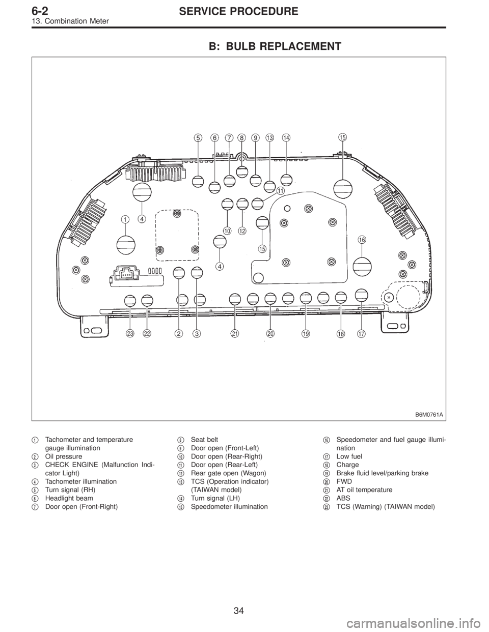
B: BULB REPLACEMENT
B6M0761A
�1Tachometer and temperature
gauge illumination
�
2Oil pressure
�
3CHECK ENGINE (Malfunction Indi-
cator Light)
�
4Tachometer illumination
�
5Turn signal (RH)
�
6Headlight beam
�
7Door open (Front-Right)�
8Seat belt
�
9Door open (Front-Left)
�
10Door open (Rear-Right)
�
11Door open (Rear-Left)
�
12Rear gate open (Wagon)
�
13TCS (Operation indicator)
(TAIWAN model)
�
14Turn signal (LH)
�
15Speedometer illumination�
16Speedometer and fuel gauge illumi-
nation
�
17Low fuel
�
18Charge
�
19Brake fluid level/parking brake
�
20FWD
�
21AT oil temperature
�
22ABS
�
23TCS (Warning) (TAIWAN model)
34
6-2SERVICE PROCEDURE
13. Combination Meter
 Remove bolts (engine compartment side) from bumper
stays.
B5M0276
10) Remove front bumper assembly.
NOTE:
Front bumper surface is accessible for removal after
removing the following parts:")
 Look at the beam angle gauge (vertical movement).
The bubble on the gauge should not deviate from the cen-
ter of the gauge.
B6M0825A
3) Look at the beam angle gauge (horizontal movement).")
![SUBARU LEGACY 1997 Service Repair Manual 6. Turn Signal and Hazard Warning
Light
A: REMOVAL AND INSTALLATION
1. FRONT TURN SIGNAL LIGHT
Refer to 6-2 [W4B2] as for removal and installation of front
turn signal light.
NOTE:
The front turn sign](/manual-img/17/57434/w960_57434-1756.png "SUBARU LEGACY 1997 Service Repair Manual 6. Turn Signal and Hazard Warning
Light
A: REMOVAL AND INSTALLATION
1. FRONT TURN SIGNAL LIGHT
Refer to 6-2 [W4B2] as for removal and installation of front
turn signal light.
NOTE:
The front turn sign")