Page 343 of 3342

1. Engine
A: SPECIFICATIONS
EngineModel2500 cc
TypeHorizontally opposed, liquid cooled, 4-cylinder, 4-stroke
gasoline engine
Valve arrangement Belt driven, double over-head camshaft, 4-valve/cylinder
Bore x Stroke mm (in) 99.5 x 79.0 (3.917 x 3.110)
Displacement cm
3(cu in) 2,457 (149.93)
Compression ratio9.5
Compression pressure
(at 200 — 300 rpm)
kPa (kg/cm
2, psi) � rpmStandard 1,216 (12.4, 176) � 350
Limit 941 (9.6, 137) � 350
Number of piston rings Pressure ring: 2, Oil ring: 1
Intake valve timingOpening 6° BTDC
Closing 50° ABDC
Exhaust valve timingOpening Front: 54° BBDC, Rear: 30° BBDC (Position in degrees)
Closing Front: 10° ATDC, Rear: 10° ATDC (Position in degrees)
Valve clearanceIntake mm (in) 0.20±0.02 (0.0079±0.0008)
Exhaust mm (in) 0.25±0.02 (0.0098±0.0008)
Idling speed
[At neutral position on MT, or
“P” or “N” position on AT] rpm700±100 (No load)
850±50 (A/C switch ON)
Firing order1,3,2,4
Ignition timing BTDC/rpm 15°±8°/700 rpm
2
2-3bSPECIFICATIONS AND SERVICE DATA
1. Engine
Page 344 of 3342

Belt ten-
sionerSpacer O.D. 16 mm (0.63 in)
Tensioner bush I.D. 16.16 mm (0.6362 in)
Clearance between")
B: SERVICE DATA
Belt
tension
adjusterProtrusion of adjuster rod 15.4—16.4 mm (0.606—0.646 in)
Belt ten-
sionerSpacer O.D. 16 mm (0.63 in)
Tensioner bush I.D. 16.16 mm (0.6362 in)
Clearance between spacer and bushSTD 0.117—0.180 mm (0.0046—0.0071 in)
Limit 0.230 mm (0.0091 in)
Side clearance of spacerSTD 0.37—0.54 mm (0.0146—0.0213 in)
Limit 0.8 mm (0.031 in)
CamshaftBend limit 0.020 mm (0.0008 in)
Thrust clearanceSTD 0.040—0.080 mm (0.0016—0.0031 in)
Limit 0.10 mm (0.0039 in)
Cam lobe heightIntakeSTD 42.20—42.30 mm (1.6614—1.6654 in)
Limit 42.04 mm (1.6551 in)
ExhaustSTDFront: 42.50—42.60 mm
Rear: 41.40—41.50 mm(1.6732—1.6772 in)
(1.6299—1.6339 in)
LimitFront: 42.34 mm
Rear: 41.24 mm(1.6669 in)
(1.6236 in)
Camshaft journal O.D.Front 31.946—31.963 mm (1.2577—1.2584 in)
Center 27.946—27.963 mm (1.1002—1.1009 in)
Rear 27.946—27.963 mm (1.1002—1.1009 in)
Camshaft journal hole I.D.Front 32.000—32.018 mm (1.2598—1.2605 in)
Center 28.000—28.018 mm (1.1024—1.1031 in)
Rear 28.000—28.018 mm (1.1024—1.1031 in)
Oil clearanceSTD 0.037—0.072 mm (0.0015—0.0028 in)
Limit 0.10 mm (0.0039 in)
Cylinder
headSurface warpage limit 0.05 mm (0.0020 in)
Surface grinding limit 0.3 mm (0.012 in)
Standard height 127.5 mm (5.02 in)
Valve seatRefacing angle 90°
Contacting widthIntakeSTD 1.0 mm (0.039 in)
Limit 1.7 mm (0.067 in)
ExhaustSTD 1.5 mm (0.059 in)
Limit 2.2 mm (0.087 in)
Valve
guideInner diameter 6.000—6.015 mm (0.2362—0.2368 in)
Protrusion above head 12.0—12.4 mm (0.472—0.488 in)
ValveHead edge thicknessIntakeSTD 1.2 mm (0.047 in)
Limit 0.8 mm (0.031 in)
ExhaustSTD 1.5 mm (0.059 in)
Limit 0.8 mm (0.031 in)
Stem diameterIntake 5.950—5.965 mm (0.2343—0.2348 in)
Exhaust 5.950—5.965 mm (0.2343—0.2348 in)
Stem oil clearanceSTDIntake 0.035—0.062 mm (0.0014—0.0024 in)
Exhaust 0.040—0.067 mm (0.0016—0.0026 in)
Limit—0.15 mm (0.0059 in)
Overall lengthIntake 105.9 mm (4.169 in)
Exhaust 106.2 mm (4.181 in)
STD: Standard I.D.: Inner Diameter O.D.: Outer Diameter
3
2-3bSPECIFICATIONS AND SERVICE DATA
1. Engine
Page 345 of 3342

Squareness 2.5°, 2.1 mm (0.083 in)
Tension/spring height146.1—167.7 N
(14.9—17.1 kg, 32.9—37.7 lb)/42.0 mm (1.654 in)
455.0—523.7 N
(46.4—53.4 k")
Valve springFree length 48.04 mm (1.8913 in)
Squareness 2.5°, 2.1 mm (0.083 in)
Tension/spring height146.1—167.7 N
(14.9—17.1 kg, 32.9—37.7 lb)/42.0 mm (1.654 in)
455.0—523.7 N
(46.4—53.4 kg, 102.3—117.7 lb)/33.4 mm (1.315 in)
Cylinder
blockSurface warpage limit (mating with cylinder head) 0.05 mm (0.0020 in)
Surface grinding limit 0.1 mm (0.004 in)
Cylinder bore STDA 99.505—99.515 mm (3.9175—3.9179 in)
B 99.495—99.505 mm (3.9171—3.9175 in)
TaperSTD 0.015 mm (0.0006 in)
Limit 0.050 mm (0.0020 in)
Out-of-roundnessSTD 0.010 mm (0.0004 in)
Limit 0.050 mm (0.0020 in)
Piston clearanceSTD 0.010—0.030 mm (0.0004—0.0012 in)
Limit 0.050 mm (0.0020 in)
Enlarging (boring) limit 0.5 mm (0.020 in)
Piston Outer diameterSTDA 99.485—99.495 mm (3.9167—3.9171 in)
B 99.475—99.485 mm (3.9163—3.9167 in)
0.25 mm (0.0098 in)
OS99.725—99.735 mm (3.9262—3.9266 in)
0.50 mm (0.0197 in)
OS99.975—99.985 mm (3.9360—3.9364 in)
Piston pinStandard clearance between piston
pin and hole in pistonSTD 0.004—0.010 mm (0.0002—0.0004 in)
Limit 0.020 mm (0.0008 in)
Degree of fitPiston pin must be fitted into position with thumb at 20°C
(68°F).
Piston ringPiston ring gapTop ringSTD 0.20—0.35 mm (0.0079—0.0138 in)
Limit 1.0 mm (0.039 in)
Second
ringSTD 0.37—0.52 mm (0.0146—0.0205 in)
Limit 1.0 mm (0.039 in)
Oil ringSTD 0.20—0.60 mm (0.0079—0.0236 in)
Limit 1.5 mm (0.059 in)
Clearance between piston
ring and piston ring grooveTop ringSTD 0.040—0.080mm (0.0016—0.0031 in)
Limit 0.15 mm (0.0059 in)
Second
ringSTD 0.030—0.070 mm (0.0012—0.0028 in)
Limit 0.15 mm (0.0059 in)
Connecting
rodBend twist per 100 mm (3.94 in) in
lengthLimit 0.10 mm (0.0039 in)
Side clearanceSTD 0.070—0.330 mm (0.0028—0.0130 in)
Limit 0.4 mm (0.016 in)
Connecting
rod bearingOil clearanceSTD 0.010—0.038 mm (0.0004—0.0015 in)
Limit 0.05 mm (0.0020 in)
Thickness at center portionSTD 1.492—1.501 mm (0.0587—0.0591 in)
0.03 mm
(0.0012 in)
US1.510—1.513 mm (0.0594—0.0596 in)
0.05 mm
(0.0020 in)
US1.520—1.523 mm (0.0598—0.0600 in)
0.25 mm
(0.0098 in)
US1.620—1.623 mm (0.0638—0.0639 in)
Connecting
rod bushingClearance between piston pin and
bushingSTD 0—0.022 mm (0—0.0009 in)
Limit 0.030 mm (0.0012 in)
STD: Standard OS: Oversize US: Undersize
4
2-3bSPECIFICATIONS AND SERVICE DATA
1. Engine
Page 366 of 3342
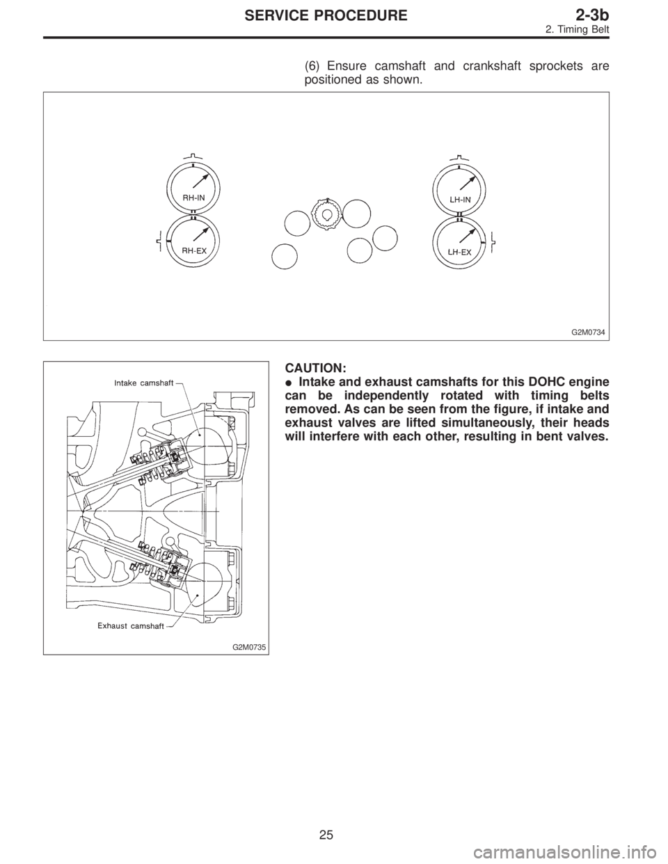
(6) Ensure camshaft and crankshaft sprockets are
positioned as shown.
G2M0734
G2M0735
CAUTION:
�Intake and exhaust camshafts for this DOHC engine
can be independently rotated with timing belts
removed. As can be seen from the figure, if intake and
exhaust valves are lifted simultaneously, their heads
will interfere with each other, resulting in bent valves.
25
2-3bSERVICE PROCEDURE
2. Timing Belt
Page 374 of 3342
C: INSTALLATION
1. CAMSHAFT
B2M1304F
Tightening torque: N⋅m (kg-m, ft-lb)
T1: 5±0.5 (0.5±0.05, 3.6±0.4)
T2: 10±0.7 (1.0±0.07, 7.2±0.5)
T3: 20±2 (2.0±0.2, 14.5±1.4)
B2M1200A
1) Camshaft installation
Apply engine oil to cylinder head at camshaft bearing loca-
tion before installing camshaft. Install camshaft so that
rocker arm is close to or in contact with“base circle”of cam
lobe.
CAUTION:
�When camshafts are positioned as shown in figure,
camshafts need to be rotated at a minimum to align
with timing belt during installation.
�Right-hand camshaft need not be rotated when set
at position shown in figure.
Left-hand intake camshaft: Rotate 80°clockwise.
Left-hand exhaust camshaft: Rotate 45°counter-clock-
wise.
33
2-3bSERVICE PROCEDURE
3. Camshaft
Page 375 of 3342
 Camshaft cap installation
(1) Apply fluid packing sparingly to cap mating surface.
CAUTION:
Do not apply fluid packing excessively. Failure to do so
may cause excess packing to come out and")
G2M0752
2) Camshaft cap installation
(1) Apply fluid packing sparingly to cap mating surface.
CAUTION:
Do not apply fluid packing excessively. Failure to do so
may cause excess packing to come out and flow
toward oil seal, resulting in oil leaks.
Fluid packing:
THREE BOND 1215 or equivalent
G2M0753
(2) Apply engine oil to cap bearing surface and install
cap on camshaft as shown by identification mark.
(3) Gradually tighten cap in at least two stages in the
numerical order shown in figure, and then tighten to
specified torque.
(4) Similarly, tighten cap on exhaust side.
After tightening cap, ensure camshaft rotates only
slightly while holding it at“base”circle.
B2M1219A
3) Inspect for valve clearance.
Measure valve clearances using thickness gauge.
2-2 [07A2].>
If necessary, adjust valve clearances.
G2M0754
4) Camshaft oil seal installation
Apply grease to new oil seal lips and press onto front end
of camshaft by using ST1 and ST2.
CAUTION:
Use a new oil seal.
ST1 499587100 OIL SEAL INSTALLER
ST2 499597000 OIL SEAL GUIDE
G2M0755
5) Rocker cover installation
(1) Install gaskets on rocker cover.
Install peripheral rocker cover gaskets.
(2) Apply fluid packing to four front open edges of
peripheral gasket.
Fluid packing:
THREE BOND 1215 or equivalent
(3) Install rocker cover on cylinder head. Ensure gas-
ket is properly positioned during installation.
34
2-3bSERVICE PROCEDURE
3. Camshaft
Page 381 of 3342
 If the clearance between valve guide and stem exceeds
the specification, replace guide as follows:
(1) Place cylinder head on ST1 with the combustion
chamber upward so that valve guides ent")
G2M0762
2) If the clearance between valve guide and stem exceeds
the specification, replace guide as follows:
(1) Place cylinder head on ST1 with the combustion
chamber upward so that valve guides enter the holes
in ST1.
(2) Insert ST2 into valve guide and press it down to
remove valve guide.
ST1 498267600 CYLINDER HEAD TABLE
ST2 499767200 VALVE GUIDE REMOVER
G2M0763
(3) Turn cylinder head upside down and place ST as
shown in the figure.
ST 498267700 VALVE GUIDE ADJUSTER
G2M0764
(4) Before installing new valve guide, make sure that
neither scratches nor damages exist on the inside sur-
face of the valve guide holes in cylinder head.
(5) Put new valve guide, coated with sufficient oil, in
cylinder, and insert ST1 into valve guide. Press in until
the valve guide upper end is flush with the upper sur-
face of ST2.
ST1 499767200 VALVE GUIDE REMOVER
ST2 498267700 VALVE GUIDE ADJUSTER
(6) Check the valve guide protrusion.
Valve guide protrusion: L
12.0—12.4 mm (0.472—0.488 in)
(7) Ream the inside of valve guide with ST. Gently
rotate the reamer clockwise while pressing it lightly into
valve guide, and return it also rotating clockwise. After
reaming, clean valve guide to remove chips.
ST 499767400 VALVE GUIDE REAMER
CAUTION:
�Apply engine oil to the reamer when reaming.
�If the inner surface of the valve guide is torn, the
edge of the reamer should be slightly ground with an
oil stone.
�If the inner surface of the valve guide becomes lus-
trous and the reamer does not chips, use a new reamer
or remedy the reamer.
(8) Recheck the contact condition between valve and
valve seat after replacing valve guide.
40
2-3bSERVICE PROCEDURE
4. Cylinder Head
Page 383 of 3342
CAUTION:
�Apply engine oil to oil seal before force-fitting.
�Differentiate between intake valve oil seal and
exhaust valve oil seal by noting their difference in
color.
Color of rubber part:
Intake [Black]
Exhaust [Brown]
Color of spring part:
Intake [Black]
Exhaust [Black]
G2M0766
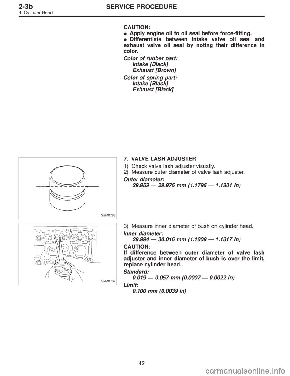
7. VALVE LASH ADJUSTER
1) Check valve lash adjuster visually.
2) Measure outer diameter of valve lash adjuster.
Outer diameter:
29.959—29.975 mm (1.1795—1.1801 in)
G2M0767
3) Measure inner diameter of bush on cylinder head.
Inner diameter:
29.994—30.016 mm (1.1809—1.1817 in)
CAUTION:
If difference between outer diameter of valve lash
adjuster and inner diameter of bush is over the limit,
replace cylinder head.
Standard:
0.019—0.057 mm (0.0007—0.0022 in)
Limit:
0.100 mm (0.0039 in)
42
2-3bSERVICE PROCEDURE
4. Cylinder Head

T1: 5±0.5 (0.5±0.05, 3.6±0.4)
T2: 10±0.7 (1.0±0.07, 7.2±0.5)
T3: 20±2 (2.0±0.2, 14.5±1.4)
B2M1200A
1) Camshaft inst")