Page 483 of 3342
B2M0019
22) Disconnect engine harness connectors from bulkhead
harness connectors, and remove engine harness connec-
tors from bracket.
B2M0345A
23) Disconnect connectors from engine coolant tempera-
ture sensor�
1and thermometer�2.
B2M1243A
24) Disconnect knock sensor connector.
B2M1251A
25) Disconnect connector from camshaft position sensor.
B2M1252A
26) Disconnect connector from crankshaft position sensor.
14
2-7SERVICE PROCEDURE
4. Intake Manifold
Page 484 of 3342
B2M1253A
27) Disconnect connector from oil pressure switch.
G2M0296
28) Disconnect fuel hoses from fuel pipes.
WARNING:
Catch fuel from hoses in a container.
B2M0159
29) Remove bolts which hold intake manifold onto cylinder
heads.
B2M0160
30) Remove intake manifold.
B2M0757A
B: DISASSEMBLY
1) Disconnect engine ground terminal from intake mani-
fold.
15
2-7SERVICE PROCEDURE
4. Intake Manifold
Page 486 of 3342
B2M0157
3) Assemble throttle body to intake manifold.
CAUTION:
Replace gasket with a new one.
Tightening torque:
22±2 N⋅m (2.2±0.2 kg-m, 15.9±1.4 ft-lb)
H2M1247
4) Install idle air control solenoid valve to intake manifold.
CAUTION:
Replace gasket with a new one.
Tightening torque:
6.4±0.5 N⋅m (0.65±0.05 kg-m, 4.7±0.4 ft-lb)
B2M0347A
5) Install engine harness onto intake manifold.
6) Connect connectors to throttle position sensor, ignition
coil, fuel injectors, idle air control solenoid valve, purge
control solenoid valve and EGR solenoid valve.
�
1EGR solenoid valve
�
2Throttle position sensor
�
3Idle air control solenoid valve
�
4Purge control solenoid valve
�
5Harness band
B2M0757A
7) Connect engine ground terminal to intake manifold.
B2M0159
D: INSTALLATION
1) Install intake manifold onto cylinder heads.
CAUTION:
Always use new gaskets.
Tightening torque:
25±2 N⋅m (2.5±0.2 kg-m, 18.1±1.4 ft-lb)
17
2-7SERVICE PROCEDURE
4. Intake Manifold
Page 488 of 3342
B2M0345A
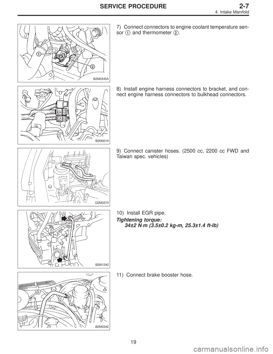
7) Connect connectors to engine coolant temperature sen-
sor�
1and thermometer�2.
B2M0019
8) Install engine harness connectors to bracket, and con-
nect engine harness connectors to bulkhead connectors.
G2M0370
9) Connect canister hoses. (2500 cc, 2200 cc FWD and
Taiwan spec. vehicles)
B2M1242
10) Install EGR pipe.
Tightening torque:
34±2 N⋅m (3.5±0.2 kg-m, 25.3±1.4 ft-lb)
B2M0342
11) Connect brake booster hose.
19
2-7SERVICE PROCEDURE
4. Intake Manifold
Page 575 of 3342
5) After remounting engine and transmission on body;
6) Bleed air from oil line with the help of a co-worker.
G2M0242
4. Clutch Disc and Cover
A: REMOVAL
1) Install ST on flywheel.
ST 498497100 CRANKSHAFT STOPPER
2) Remove clutch cover and clutch disc.
CAUTION:
�Take care not to allow oil on the clutch disc facing.
�Do not disassemble either clutch cover or clutch
disc.
G2M0243
3) Remove flywheel.
B2M0328
B: INSPECTION
1. CLUTCH DISC
1) Facing wear
Measure the depth of rivet head from the surface of facing.
Replace if facings are worn locally or worn down to less
than the specified value.
Depth of rivet head:
Standard value
1.3—1.9 mm (0.051—0.075 in)
Limit of sinking
0.3 mm (0.012 in)
CAUTION:
Do not wash clutch disc with any cleaning fluid.
12
2-10SERVICE PROCEDURE
3. Release Bearing and Lever - 4. Clutch Disc and Cover
Page 576 of 3342
5) After remounting engine and transmission on body;
6) Bleed air from oil line with the help of a co-worker.
G2M0242
4. Clutch Disc and Cover
A: REMOVAL
1) Install ST on flywheel.
ST 498497100 CRANKSHAFT STOPPER
2) Remove clutch cover and clutch disc.
CAUTION:
�Take care not to allow oil on the clutch disc facing.
�Do not disassemble either clutch cover or clutch
disc.
G2M0243
3) Remove flywheel.
B2M0328
B: INSPECTION
1. CLUTCH DISC
1) Facing wear
Measure the depth of rivet head from the surface of facing.
Replace if facings are worn locally or worn down to less
than the specified value.
Depth of rivet head:
Standard value
1.3—1.9 mm (0.051—0.075 in)
Limit of sinking
0.3 mm (0.012 in)
CAUTION:
Do not wash clutch disc with any cleaning fluid.
12
2-10SERVICE PROCEDURE
3. Release Bearing and Lever - 4. Clutch Disc and Cover
Page 1186 of 3342
 17 (0.67)
Turning angleInner tire & wheel 37.6°34.4°
Outer tire & wheel 32.6°30.2°
Steering shaftClearance betwe")
B: SERVICE DATA
Except OUTBACK model OUTBACK model
Steering wheel Free play mm (in) 17 (0.67)
Turning angleInner tire & wheel 37.6°34.4°
Outer tire & wheel 32.6°30.2°
Steering shaftClearance between steering
wheel and column cover
mm (in)3.0 (0.118)
Steering gearbox
(Power steering system)Sliding resistance N (kg, lb) 240.3 (24.5, 54.0) or less
Rack shaft play in radial direc-
tion
mm (in)0.15 (0.0059) or less
Right-turn steering Horizontal movement: 0.3 (0.012) or less
Left-turn steering Vertical movement: 0.15 (0.0059) or less
Input shaft play mm (in)
In radial direction 0.18 (0.0071) or less
In axial direction 0.1 (0.004) or less
Turning resistance N (kg, lb)Within 30 mm (1.18 in) from rack center in straight ahead
position: Less than 11.18 (1.14, 2.51)
Maximum allowable value: 12.7 (1.3, 2.9)
Oil pump (Power steering sys-
tem)Pulley shaft mm (in)
Radial play 0.4 (0.016) or less
Axial play 0.9 (0.035) or less
Pulley
Ditch deflection mm (in)
Resistance to rotation
N (kg, lb)1.0 (0.039) or less
9.22 (0.94, 2.07) or less
Regular pressure
kPa (kg/cm
2, psi)981 (10, 142) or less
Relief pressure
kPa (kg/cm
2, psi)7,355 (75, 1,067)
Steering wheel effort
(Power steering system)At standstill with engine
idling on a concrete road
N (kg, lb)31.4 (3.2, 7.1) or less
At standstill with engine
stalled on a concrete road
N (kg, lb)147 (15, 33) or less
C: RECOMMENDED POWER STEERING
FLUID
Recommended power steering fluid Manufacturer
ATF DEXRON II, ATF DEXRON IIE or ATF
DEXRON IIIB.P.
CALTEX
CASTROL
MOBIL
SHELL
TEXACO
3
4-3SPECIFICATIONS AND SERVICE DATA
1. Steering System
Page 1343 of 3342
 Drain brake fluid from reservoir of master cylinder.
2) Remove adjusting nut and cable clamp, and disconnect
PHV cable from cable bracket on engine.
3) Detach PHV")
G4M0428
8. Hill Holder
A: REMOVAL
1) Drain brake fluid from reservoir of master cylinder.
2) Remove adjusting nut and cable clamp, and disconnect
PHV cable from cable bracket on engine.
3) Detach PHV cable from clips.
4) Remove cable clamp, and disconnect PHV cable from
PHV stay.
CAUTION:
Carefully protect boots and inner cable from damage
when disconnecting PHV cable.
5) Disconnect brake pipes from PHV.
CAUTION:
�Pay attention not to drop brake fluid onto body
painting since it may dissolve paint.
�Pay attention not to damage hexagonal head of flare
nut by using pipe wrench without fail.
6) Detach PHV along with support from side frame.
CAUTION:
Exercise utmost care to prevent foreign matter from
entering into PHV when removing it.
B: INSPECTION
Check up removed parts as follows, and replace defective
ones.
1) Check if boots of PHV cable are damaged or degraded,
and if inner cable is damaged or corroded.
2) Check if return spring is worn out, damaged or cor-
roded.
3) Confirm that rolling sound of ball is heard with PHV
inclined and lever rotates smoothly.
CAUTION:
Never disassemble PHV. Replace entire PHV assembly
if necessary.
62
4-4SERVICE PROCEDURE
8. Hill Holder
 Disconnect engine harness connectors from bulkhead
harness connectors, and remove engine harness connec-
tors from bracket.
B2M0345A
23) Disconnect connectors from engine coolant tempera-")
 Disconnect connector from oil pressure switch.
G2M0296
28) Disconnect fuel hoses from fuel pipes.
WARNING:
Catch fuel from hoses in a container.
B2M0159
29) Remove bolts which hold intake")
 Assemble throttle body to intake manifold.
CAUTION:
Replace gasket with a new one.
Tightening torque:
22±2 N⋅m (2.2±0.2 kg-m, 15.9±1.4 ft-lb)
H2M1247
4) Install idle air control soleno")
![SUBARU LEGACY 1997 Service Repair Manual 5) After remounting engine and transmission on body;
<Ref. to 2-11 [W3B0].>
6) Bleed air from oil line with the help of a co-worker.
<Ref. to 2-10 [W202].>
G2M0242
4. Clutch Disc and Cover
A: REMOVAL](/manual-img/17/57434/w960_57434-574.png "SUBARU LEGACY 1997 Service Repair Manual 5) After remounting engine and transmission on body;
<Ref. to 2-11 [W3B0].>
6) Bleed air from oil line with the help of a co-worker.
<Ref. to 2-10 [W202].>
G2M0242
4. Clutch Disc and Cover
A: REMOVAL")
![SUBARU LEGACY 1997 Service Repair Manual 5) After remounting engine and transmission on body;
<Ref. to 2-11 [W3B0].>
6) Bleed air from oil line with the help of a co-worker.
<Ref. to 2-10 [W202].>
G2M0242
4. Clutch Disc and Cover
A: REMOVAL](/manual-img/17/57434/w960_57434-575.png "SUBARU LEGACY 1997 Service Repair Manual 5) After remounting engine and transmission on body;
<Ref. to 2-11 [W3B0].>
6) Bleed air from oil line with the help of a co-worker.
<Ref. to 2-10 [W202].>
G2M0242
4. Clutch Disc and Cover
A: REMOVAL")