Page 1911 of 3342
G3M0725
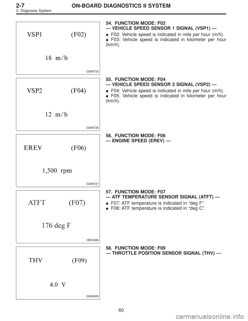
54. FUNCTION MODE: F02
—VEHICLE SPEED SENSOR 1 SIGNAL (VSP1)—
�F02: Vehicle speed is indicated in mile per hour (m/h).
�F03: Vehicle speed is indicated in kilometer per hour
(km/h).
G3M0726
55. FUNCTION MODE: F04
—VEHICLE SPEED SENSOR 2 SIGNAL (VSP2)—
�F04: Vehicle speed is indicated in mile per hour (m/h).
�F05: Vehicle speed is indicated in kilometer per hour
(km/h).
G3M0727
56. FUNCTION MODE: F06
—ENGINE SPEED (EREV)—
OBD0386
57. FUNCTION MODE: F07
—ATF TEMPERATURE SENSOR SIGNAL (ATFT)—
�F07: ATF temperature is indicated in“deg F”.
�F08: ATF temperature is indicated in“deg C”.
G3M0935
58. FUNCTION MODE: F09
—THROTTLE POSITION SENSOR SIGNAL (THV)—
60
2-7ON-BOARD DIAGNOSTICS II SYSTEM
3. Diagnosis System
Page 1912 of 3342
G3M0730
59. FUNCTION MODE: F10
—GEAR POSITION (GEAR)—
G3M0731
60. FUNCTION MODE: F11
—LINE PRESSURE DUTY RATIO (PLDTY)—
G3M0732
61. FUNCTION MODE: F12
—LOCK-UP DUTY RATIO (LUDTY)—
G3M0733
62. FUNCTION MODE: F13
—AWD DUTY RATIO (4WDTY)—
B3M0259
63. FUNCTION MODE: F14
—THROTTLE POSITION SENSOR POWER SUPPLY
VOLTAGE (THVCC)—
61
2-7ON-BOARD DIAGNOSTICS II SYSTEM
3. Diagnosis System
Page 1913 of 3342
B3M0370
64. FUNCTION MODE: F15
—MASS AIR FLOW SENSOR SIGNAL (AFM)—
62
2-7ON-BOARD DIAGNOSTICS II SYSTEM
3. Diagnosis System
Page 1927 of 3342
, main relay and fuel pump relay.
CAUTION:
�All Airbag system wirin")
4. Cautions
A: SUPPLEMENTAL RESTRAINT SYSTEM
“AIRBAG”
Airbag system wiring harness is routed near the engine
control module (ECM), main relay and fuel pump relay.
CAUTION:
�All Airbag system wiring harness and connectors
are colored yellow. Do not use electrical test equip-
ment on these circuit.
�Be careful not to damage Airbag system wiring har-
ness when servicing the engine control module (ECM),
transmission control module (TCM), main relay and
fuel pump relay.
B: PRECAUTIONS
1) Never connect the battery in reverse polarity.
�The ECM will be destroyed instantly.
�The fuel injector and other part will be damaged in just
a few minutes more.
2) Do not disconnect the battery terminals while the
engine is running.
�A large counter electromotive force will be generated in
the alternator, and this voltage may damage electronic
parts such as ECM, etc.
3) Before disconnecting the connectors of each sensor
and the ECM, be sure to turn OFF the ignition switch.
4) Before removing ECM from the located position, dis-
connect two cables on battery.
�Otherwise, the ECM may be damaged.
5) The connectors to each sensor in the engine compart-
ment and the harness connectors on the engine side and
body side are all designed to be waterproof. However, it is
still necessary to take care not to allow water to get into the
connectors when washing the vehicle, or when servicing
the vehicle on a rainy day.
H2M1154A
6) Use ECM mounting stud bolts at the body head ground-
ing point when measuring voltage and resistance inside the
passenger compartment.
76
2-7ON-BOARD DIAGNOSTICS II SYSTEM
4. Cautions
Page 1930 of 3342
 I/O SIGNAL
OBD0092A
ContentConnector
No.Terminal
No.Signal (V)
Note
Ignition SW ON
(Engine OFF)Engine ON (Idling)
Crankshaft
position
sensorSignal (+)")
5. Specified Data
1. ENGINE CONTROL MODULE (ECM) I/O SIGNAL
OBD0092A
ContentConnector
No.Terminal
No.Signal (V)
Note
Ignition SW ON
(Engine OFF)Engine ON (Idling)
Crankshaft
position
sensorSignal (+) B84 8 0�7—+7 Sensor output waveform
Signal (�) B84 29 0 0—
Shield B84 54 0 0—
Camshaft
position
sensorSignal (+) B84 7 0�7—+7 Sensor output waveform
Signal (�) B84 28 0 0—
Shield B84 54 0 0—
Mass air
flow sensorSignal B84 5 0—0.3 0.8—1.2—
Shield B84 57 0 0—
GND B84 53 0 0—
Throttle
position
sensorSignal B84 6Fully closed: 0.2—1.0
Fully opened: 4.2—4.7—
Power
supplyB84 21 5 5—
GND B84 20 0 0—
Front
oxygen
sensorSignal B84 23 0 0—0.9—
Shield B84 56 0 0—
Rear
oxygen
sensorSignal B84 24 0 0—0.9—
Shield B84 56 0 0—
Engine coolant
temperature sensorB84 22 1.0—1.4 1.0—1.4 After warm-up
Vehicle speed sensor 2 B84 83 0 or 5 0 or 5“5”and“0”are repeatedly
displayed when vehicle is
driven.
Starter switch B84 86 0 0 Cranking: 8 to 14
A/C switch B84 60ON: 10—13
OFF: 0ON: 13—14
OFF: 0—
Ignition switch B84 85 10—13 13—14—
Neutral position switch
(MT)
B84 82ON: 5.0±0.5
OFF: 0�On MT model; switch is ON
when gear is in neutral position.
Neutral position switch
(AT)ON: 0
OFF: 5.0±0.5�On AT model; switch is ON when
shift is in“N”or“P”position.
Test mode connector B84 84 5 5 When connected: 0
79
2-7ON-BOARD DIAGNOSTICS II SYSTEM
5. Specified Data
Page 1931 of 3342

Note
Ignition SW ON
(Engine OFF)Engine ON (Idling)
Knock
sensorSignal B84 3 2.8 2.8—
Shield B84 56 0 0—
AT/MT identification B84 81(AT) 5
(MT) 0(AT) 5
(M")
ContentConnector
No.Terminal
No.Signal (V)
Note
Ignition SW ON
(Engine OFF)Engine ON (Idling)
Knock
sensorSignal B84 3 2.8 2.8—
Shield B84 56 0 0—
AT/MT identification B84 81(AT) 5
(MT) 0(AT) 5
(MT) 0When measuring voltage between
ECM and body.
Back-up power supply B84 39 10—13 13—14 Ignition switch“OFF”:10—13
Control unit power supply B841
10—13 13—14—
2
Ignition
control#1,#2 B84 41 0 1—3.4—
#3,#4 B84 40 0 1—3.4—
Fuel
injector# 1 B84 96 10—13 1—14 Waveform
# 2 B84 70 10—13 1—14 Waveform
# 3 B84 44 10—13 1—14 Waveform
# 4 B84 16 10—13 1—14 Waveform
Idle air
control
solenoid
valveOPEN end B84 14—1—13 Waveform
CLOSE end B84 13—13—1 Waveform
Fuel pump relay control B84 32ON: 0.5, or less
OFF: 10—130.5, or less—
A/C relay control B84 31ON: 0.5, or less
OFF: 10—13ON: 0.5, or less
OFF: 13—14—
Radiator fan relay 1
controlB84 74ON: 0.5, or less
OFF: 10—13ON: 0.5, or less
OFF: 13—14—
Radiator fan relay 2
controlB84 73ON: 0.5, or less
OFF: 10—13ON: 0.5, or less
OFF: 13—14With A/C vehicles only
Self-shutoff control B84 63 10—13 13—14—
Malfunction indicator lamp B84 58——Light“ON”:1,orless
Light“OFF”:10—14
Engine speed output B84 64—0—13, or more Waveform
Torque control signal B84 79 5 5—
Mass air flow signal for
ATB84 47 0—0.3 0.8—1.2—
Purge control solenoid
valveB84 72ON: 1, or less
OFF: 10—13ON: 1, or less
OFF: 13—14—
Atmospheric pressure
sensorB84 26 3.9—4.1 2.0—2.3—
Pressure sources
switching solenoid valveB84 15ON: 1, or less
OFF: 10—13ON: 1, or less
OFF: 13—14—
EGR solenoid valve B84 71ON: 1, or less
OFF: 10—13ON: 1, or less
OFF: 13—14—
Front oxygen sensor
heater signalB84 38 0—1.0 0—1.0—
Rear oxygen sensor
heater signalB84 37 0—1.0 0—1.0—
Fuel temperature sensor B84 25 2.5—3.8 2.5—3.8�2200 cc AWD except Taiwan
spec. vehicles
�Ambient temperature: 25°C
(77°F)
Fuel level sensor B84 27 0.12—4.75 0.12—4.75 2200 cc AWD except Taiwan model
Fuel tank
pressure
sensorSignal B84 4 2.3—2.7 2.3—2.7�2200 cc AWD except Taiwan
spec. vehicles
�The value obtained after the fuel
filler cap was removed once and
recapped.
Power
supplyB84 21 5 5—
GND B84 20 0 0—
Fuel tank pressure control
solenoid valveB84 10ON: 1, or less
OFF: 10—13ON: 1, or less
OFF: 13—142200 cc AWD except Taiwan spec.
vehicles
Vent control solenoid
valveB84 35ON: 1, or less
OFF: 10—13ON: 1, or less
OFF: 13—142200 cc AWD except Taiwan spec.
vehicles
TCS signal B84 61 0—70—7 Waveform
80
2-7ON-BOARD DIAGNOSTICS II SYSTEM
5. Specified Data
Page 1932 of 3342
ContentConnector
No.Terminal
No.Signal (V)
Note
Ignition SW ON
(Engine OFF)Engine ON (Idling)
AT diagnosis input signal B84 80Less than 1)More
than 4Less than 1)More
than 4Waveform
GND (sensors) B84 20 0 0—
GND (injectors) B8469
00—
95
GND (ignition system) B84 94 0 0—
GND (power supply) B8419
00—
46
GND (control systems) B8417
00—
18
GND (oxygen sensor
heater)B84 42 0 0—
2. ENGINE CONDITION DATA
Content Model Specified data
Mass air flow2200 cc1.7—3.3 (g/sec): Idling
7.1—14.2 (g/sec): 2,500 rpm racing
2500 cc2.2—4.2 (g/sec): Idling
8.6—14.5 (g/sec): 2,500 rpm racing
Engine load2200 cc1.6—2.9 (%): Idling
6.4—12.8 (%): 2,500 rpm racing
2500 cc1.9—3.5 (%): Idling
7.2—12.1 (%): 2,500 rpm racing
Measuring condition:
�After warm-up the engine.
�Gear position is in“N”or“P”position.
�A/C is turned OFF.
�All accessory switches are turned OFF.
81
2-7ON-BOARD DIAGNOSTICS II SYSTEM
5. Specified Data
Page 1934 of 3342
Resistance to
body
(ohms)
Throttle position
sensorB54 8Throttle fully closed. 0.3—0.7
—
Throttle fully open. 4.3—4.9
Throttle posit")
ContentConnector
No.Terminal
No.Measuring conditionsVoltage
(V)Resistance to
body
(ohms)
Throttle position
sensorB54 8Throttle fully closed. 0.3—0.7
—
Throttle fully open. 4.3—4.9
Throttle position
sensor power
supplyB56 19Ignition switch ON (with engine
OFF)4.8—5.3—
ATF temperature
sensorB54 10ATF temperature 20°C(68°F) 2.9—4.0 2.1 k—2.9 k
ATF temperature 80°C (176°F) 1.0—1.4 275—375
Vehicle speed
sensor 1B54 12Vehicle stopped. 0
450—720
Vehicle speed at least 20 km/h (12
MPH)More than 1 (AC range)
Vehicle speed
sensor 2B56 11When vehicle is slowly moved at
least 2 meters (7ft).Less than 1)More than 9—
Engine speed
signalB54 5Ignition switch ON (with engine
OFF).More than 10.5
—
Ignition switch ON (with engine ON). 8—11
Cruise set signal B56 3When cruise control is set (SET
lamp ON).Less than 1
—
When cruise control is not set (SET
lamp OFF).More than 6.5
Torque control
signalB55 16 Ignition switch ON 4—6—
Mass air flow
signalB54 9 Engine idling after warm-up 0.5—1.2—
Shift solenoid 1 B55 141st or 4th gear More than 9
20—32
2nd or 3rd gear Less than 1
Shift solenoid 2 B55 131st or 2nd gear More than 9
20—32
3rd or 4th gear Less than 1
Shift solenoid 3 B55 15Selector lever in“N”range (with
throttle fully closed).Less than 1
20—32
Selector lever in“D”range (with
throttle fully closed).More than 9
Duty solenoid A B55 8Throttle fully closed (with engine
OFF) after warm-up.2.0—4.0
2.0—4.5
Throttle fully open (with engine
OFF) after warm-up.Less than 1
Dropping resistor B55 7Throttle fully closed (with engine
OFF) after warm-up.More than 8.5
12—18
Throttle fully open (with engine
OFF) after warm-up.Less than 1
Duty solenoid B B55 5When lock up occurs. More than 8.5
9—17
When lock up is released. Less than 0.5
Duty solenoid C
(AWD model only)B55 3Fuse on FWD switch More than 8.5
9—17 Fuse removed from FWD switch
(with throttle fully open and with
select lever in 1st gear).Less than 0.5
Sensor ground
line 1B54 7—0 Less than 1
Sensor ground
line 2B56 20—0 Less than 1
System ground
lineB56 1—0 Less than 1
Power system
ground lineB55 10—0 Less than 1
FWD switch
(AWD model only)B56 2Fuse removed. 6—9.1
—
Fuse installed. Less than 1
Data link signal
(Subaru select
monitor)B5612——
—
13——
AT diagnosis
signalB56 11 Ignition switch ON Less than 1)More than 4—
83
2-7ON-BOARD DIAGNOSTICS II SYSTEM
5. Specified Data
—
G3M0731
60. FUNCTION MODE: F11
—LINE PRESSURE DUTY RATIO (PLDTY)—
G3M0732
61. FUNCTION MODE: F12
—LOCK-UP DUTY RATIO (LUDTY)—
G3M0733")
—
62
2-7ON-BOARD DIAGNOSTICS II SYSTEM
3. Diagnosis System")

Note
Ignition SW ON
(Engine OFF)Engine ON (Idling)
AT diagnosis input signal B84 80Less than 1)More
than 4Less than 1)More
than 4Waveform
GND (sensors) B84 2")