Page 2393 of 3342
B2M1137
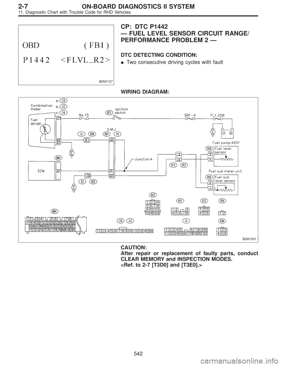
CP: DTC P1442
—FUEL LEVEL SENSOR CIRCUIT RANGE/
PERFORMANCE PROBLEM 2—
DTC DETECTING CONDITION:
�Two consecutive driving cycles with fault
WIRING DIAGRAM:
B2M1021
CAUTION:
After repair or replacement of faulty parts, conduct
CLEAR MEMORY and INSPECTION MODES.
542
2-7ON-BOARD DIAGNOSTICS II SYSTEM
11. Diagnostic Chart with Trouble Code for RHD Vehicles
Page 2394 of 3342
11CP1CHECK DTC P0461, P0462 OR P0463 ON
DISPLAY.
: Does the Subaru select monitor or OBD-II
general scan tool indicate DTC P0461,
P0462 or P0463?
: Inspect DTC P0461, P0462 or P0463 using“11 .
Diagnostics Chart with Trouble Code”.
2-7 [T11A0].>
NOTE:
In this case, it is not necessary to inspect this trouble.
: Replace fuel sending unit and fuel sub meter unit.
543
2-7ON-BOARD DIAGNOSTICS II SYSTEM
11. Diagnostic Chart with Trouble Code for RHD Vehicles
Page 3186 of 3342
G6M0205
11) Each connector number shown in the wiring diagram
corresponds to that in the wiring harness. The location of
each connector in the actual vehicle is determined by read-
ing the first character of the connector (for example, a“F”
for F8,“i”for i16, etc.) and the type of wiring harness.
The first character of each connector number refers to the
area or system of the vehicle, as indicated in table below.
Symbol Wiring harness and Cord
F Front wiring harness
B Bulkhead wiring harness
E Engine wiring harness
T Transmission cord
D Door cord LH & RH, Rear gate cord
I Instrument panel wiring harness
RRear wiring harness, Rear defogger cord
Room light cord,
Fuel tank cord,
Sunroof cord,
Trunk lid cord
P Floor wiring harness
7
6-3WIRING DIAGRAM
1. General Description
Page 3199 of 3342

MB-2 Power window circuit breaker
MB-3Engine control module
Fuel pump relay
Main relay
OBD-II service connector
MB-4 A/C relay holder
MB-5 He")
No. Load
MB-1Fuse holder (Rear power supply & seat
heater)
MB-2 Power window circuit breaker
MB-3Engine control module
Fuel pump relay
Main relay
OBD-II service connector
MB-4 A/C relay holder
MB-5 Headlight alarm relay (with security)
MB-6 Headlight LH
MB-7Daytime running light control module
Diode (Lighting)
Diode (Security)
Lighting switch
MB-8Combination meter
Front fog light switch
Headlight RH
Front fog light relay
MB-9Door lock timer
Headlight alarm relay
Interrupt relay
Radio
Security control module
Security indicator light
Spot light
Room light
Step light
Combination meter
Luggage room light
Trailer connector
Trunk room light
MB-10 A/C relay holder
SBF-6ABS relay box
TCS motor relay
SBF-7 TCS valve relay
ALT-1Combination meter
Daytime running light control module
Diode (TCS)
IG Headlight alarm relay
STCruise control module
Engine control module
Inhibitor switch (AT)
Interrupt relay
Starter interlock relay (MT)
FB-1Front washer motor
Rear washer motor
FB-2Engine control module
Main fan relay 1
FB-3Sub fan relay 2
Sub fan motor
FB-4Engine control module
Fuel pump relay
Ignition coil
Transmission control moduleNo. Load
FB-5 ABS relay box
FB-6Side marker light LH
Side marker light RH
FB-7 Door lock timer
FB-9 Hazard switch
FB-10AT shift lock control module
Key warning switch
Power antenna
FB-11 Radio
FB-12 Front accessory power supply
FB-13Mirror heater
Rear power supply relay
Remote control rearview mirror switch
Security control module
Vanity mirror illumination light
FB-14AT shift lock control module
Combination switch
Front wiper motor
Rear wiper motor
Rear wiper relay
FB-15ABS/TCS control module
Transmission control module
FB-16Rear defogger
Rear defogger condenser
Rear defogger switch
FB-17 Rear defogger switch
FB-18AT shift lock control module
Back-up light switch (MT)
Inhibitor switch (AT)
FB-19 Hazard switch
FB-20A/C switch
Combination meter
Mode control panel
TCS off switch
FB-22Blower motor relay
Check connector
Daytime running light control module
Daytime running light relay
FRESH/RECIRC actuator
Hi-beam relay
Power window and sunroof relay
Seat belt timer
FB-23 Airbag control module
FB-24 Airbag control module
FB-25 Lighting switch
20
6-3WIRING DIAGRAM
6. Wiring Diagram
Page 3203 of 3342

Lighting switch
MB")
No. Load
MB-2 Power window circuit breaker
MB-3Engine control module
Fuel pump relay
Main relay
OBD-II service connector
MB-4 A/C relay holder
MB-6 Headlight LH
MB-7Diode (Lighting)
Lighting switch
MB-8Combination meter
Headlight RH
MB-9Combination meter
Door lock timer
Luggage room light
Radio
Room light
MB-10 A/C relay holder
ALT-1 Combination meter
IG A/C relay holder
STCruise control module
Engine control module
Inhibitor switch
FB-2Engine control module
Main fan relay 1
FB-3Sub fan motor
Sub fan relay-2
FB-4Engine control module
Fuel pump relay
Ignition coil
Transmission control module
FB-6Side marker light LH
Side marker light RH
FB-7 Door lock timer
FB-9 Hazard switch
FB-10AT shift lock control module
Key warning switch
Power antenna
FB-11 Radio
FB-12 Cigarette lighter
FB-13 Remote control rearview mirror switch
FB-14AT shift lock control module
Combination switch
Front washer motor
Front wiper motor
Rear washer motor
Rear wiper motor
Rear wiper relayNo. Load
FB-15 Transmission control module
FB-16Rear defogger
Rear defogger condenser
Rear defogger switch
FB-17 Rear defogger switch
FB-18AT shift lock control module
Inhibitor switch
FB-19 Hazard switch
FB-20Combination meter
Mode control panel
FB-22Blower motor relay
Check connector
FRESH/RECIRC actuator
Mode actuator
Power window relay
Seat belt timer
FB-23 Airbag control module
FB-24 Airbag control module
FB-25 Lighting switch
FB-26 Parking switch
FB-27 Parking switch
FB-28 Illumination light
FB-29 Illumination light
FB-30Stop light switch
Stop & brake switch
FB-31 Horn relay
FB-32 Blower motor relay
FB-33 Parking switch
FB-34License plate light LH
License plate light RH
Rear combination light LH
Rear combination light RH
Rear finisher light LH
Rear finisher light RH
FB-35Cruise control main switch
Cruise control module
FB-38 Main fan relay 1
24
6-3WIRING DIAGRAM
6. Wiring Diagram
Page 3246 of 3342
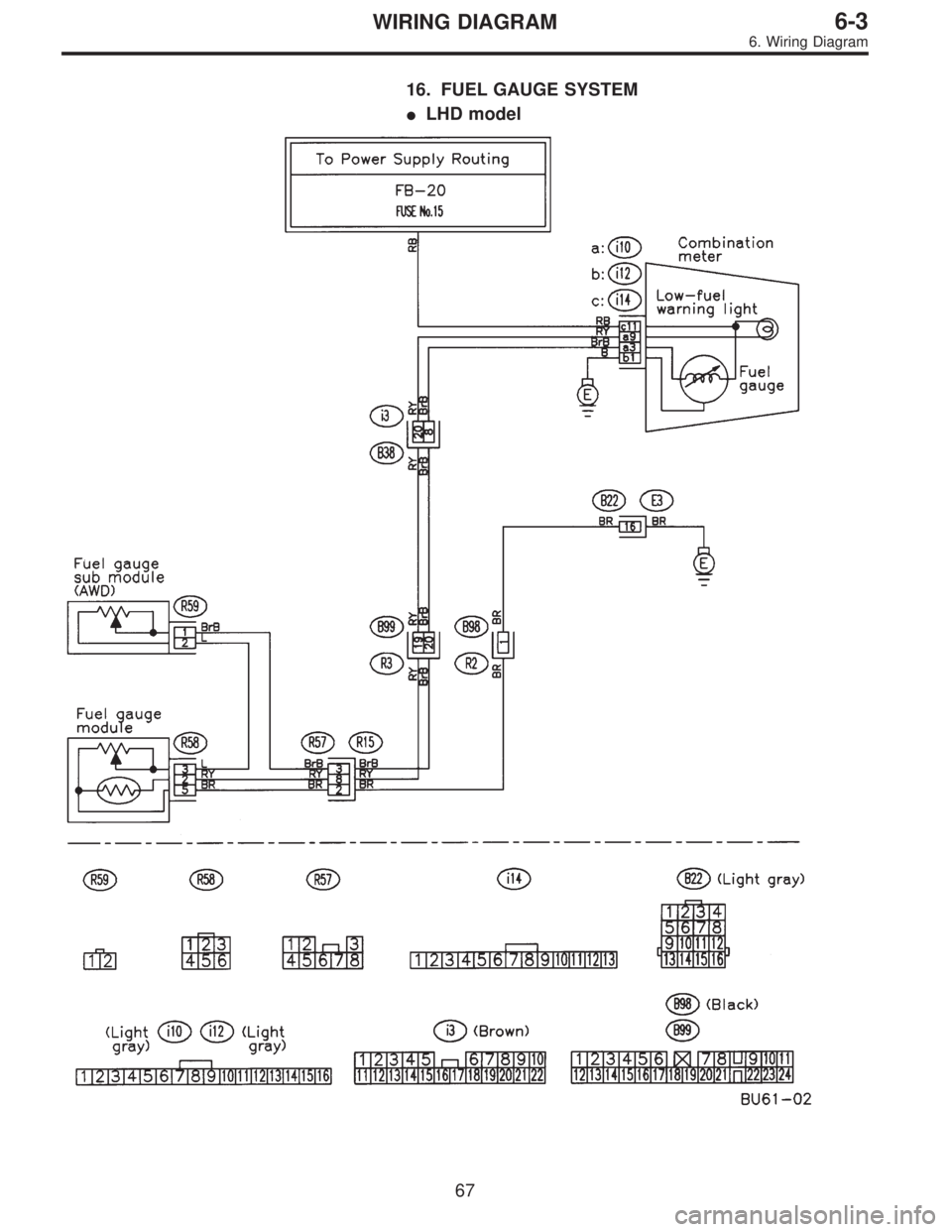
16. FUEL GAUGE SYSTEM
�LHD model
67
6-3WIRING DIAGRAM
6. Wiring Diagram
Page 3247 of 3342
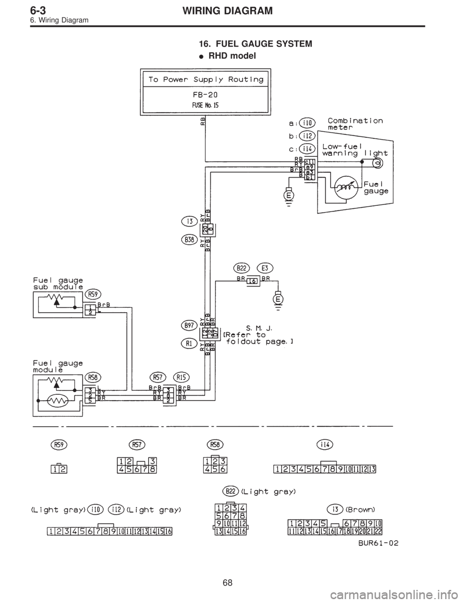
16. FUEL GAUGE SYSTEM
�RHD model
68
6-3WIRING DIAGRAM
6. Wiring Diagram
Page 3289 of 3342
![SUBARU LEGACY 1997 Service Repair Manual 7. Electrical Unit Location
Electrical unit Refer to;
A.B.S. control module 4-4a [T300]
A.B.S. G sensor (MT) 4-4a [T300]
A/C compressor relay�
7
A/C fuse�11
A/C main fan relay 1�10
A/C main fan relay](/manual-img/17/57434/w960_57434-3288.png "SUBARU LEGACY 1997 Service Repair Manual 7. Electrical Unit Location
Electrical unit Refer to;
A.B.S. control module 4-4a [T300]
A.B.S. G sensor (MT) 4-4a [T300]
A/C compressor relay�
7
A/C fuse�11
A/C main fan relay 1�10
A/C main fan relay")
7. Electrical Unit Location
Electrical unit Refer to;
A.B.S. control module 4-4a [T300]
A.B.S. G sensor (MT) 4-4a [T300]
A/C compressor relay�
7
A/C fuse�11
A/C main fan relay 1�10
A/C main fan relay 2�8
A/C pressure switch�2
A/C sub fan relay 2�9
ATF temperature sensor 2-7 [T2B1]
Blower motor resistor�
26
Blower relay�13
Camshaft position sensor 2-7 [T2A2]
Check connector�
25
Clutch switch (MT) 6-2 [T300]
Crankshaft position sensor 2-7 [T2A2]
Cruise control module 6-2 [T300]
Cruise control pump 6-2 [T300]
Data link connector (for OBD-II G.S.T.) 2-7 [T2A1]
Data link connector (for S.S.M.) 2-7 [T2A1]
Diagnosis connector 4-4a [T300]
Diagnosis terminal (Ground) 4-4a [T300]
Door lock timer�
27
Engine control module 2-7 [T2A1]
Engine coolant temperature sensor 2-7 [T2A2]
Engine hood switch (Security) 6-2 [K6A0]
Evaporator thermoswitch�
29
F/B�15
FRESH/RECIRC actuator�28
Fuel pump relay 2-7 [T2A3]
Fuel gauge module�
31
Fuel gauge sub module (AWD)�32
FWD switch (AT)�1
Headlight alarm relay (Security) 6-2 [K6A0]
Headlight relay LH�
5
Headlight relay RH�6
Horn relay�14
Electrical unit Refer to;
Hydraulic unit (A.B.S.) 4-4a [T300]
Ignition coil 2-7 [T2A3]
Ignitor 2-7 [T2A3]
Idle air control solenoid valve 2-7 [T2A3]
Illumination control module�
21
Inhibitor switch 6-2 [T300]
Knock sensor 2-7 [T2A2]
Main fan relay�
19
Main relay 2-7 [T2A3]
Mass air flow sensor 2-7 [T2A2]
Mode actuator�
12
M/B�4
Oil pressure switch�3
Oxygen sensor 2-7 [T2A2]
Pedal stroke sensor (T.C.S.) 4-4b [T300]
Power window and sunroof relay�
24
Power window circuit breaker�23
Purge control solenoid valve 2-7 [T2A3]
Rear defogger relay�
17
Seat belt timer�20
Security control module 6-2 [K6A0]
Shift lock control module�
22
Starter interrupt relay (Security) 6-2 [K6A0]
Stop & brake switch (With cruise con-
trol)6-2 [T300]
Sunroof control module�
30
Tail and illumination relay�18
T.C.S. control module 4-4b [T300]
T.C.S. motor relay 4-4b [T300]
T.C.S. valve relay 4-4b [T300]
Throttle position sensor 2-7 [T2A2]
Test mode connector 2-7 [T2A1]
Transmission control module 2-7 [T2B1]
Turn & hazard module�
16
Vehicle speed sensor 1 2-7 [T2B1]
Vehicle speed sensor 2 2-7 [T2B1]
11 0
6-3WIRING DIAGRAM
7. Electrical Unit Location

 Each connector number shown in the wiring diagram
corresponds to that in the wiring harness. The location of
each connector in the actual vehicle is determined by read-
ing the first chara")