Page 2803 of 3342
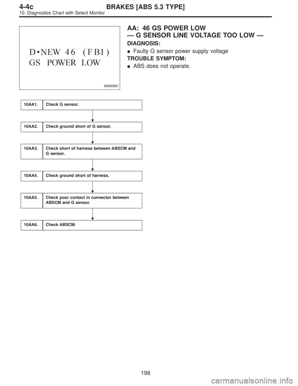
B4M0967
AA: 46 GS POWER LOW
—G SENSOR LINE VOLTAGE TOO LOW—
DIAGNOSIS:
�Faulty G sensor power supply voltage
TROUBLE SYMPTOM:
�ABS does not operate.
10AA1.Check G sensor.
10AA2.Check ground short of G sensor.
10AA3.Check short of harness between ABSCM and
G sensor.
10AA4.Check ground short of harness.
10AA5.Check poor contact in connector between
ABSCM and G sensor.
10AA6.Check ABSCM.
�
�
�
�
�
198
4-4cBRAKES [ABS 5.3 TYPE]
10. Diagnostics Chart with Select Monitor
Page 2804 of 3342
WIRING DIAGRAM:
B4M1047
B4M0851B
10AA1
CHECK G SENSOR.
1) Turn ignition switch to OFF.
2) Remove console cover from console box.
3) Disconnect connector from G sensor.
4) Measure resistance of G sensor.
: Connector & terminal
To (P11) No. 1—No. 3
Is resistance 50±8 kΩ?
: Go to step10AA2.
: Replace G sensor.
199
4-4cBRAKES [ABS 5.3 TYPE]
10. Diagnostics Chart with Select Monitor
Page 2805 of 3342
 No. 3—Bracket
Is resistance more than 1 MΩ?
: Go to step10AA3.
: Rep")
B4M0852B
10AA2
CHECK GROUND SHORT OF G SENSOR.
Measure resistance between G sensor and bracket.
: Connector & terminal
To (P11) No. 3—Bracket
Is resistance more than 1 MΩ?
: Go to step10AA3.
: Replace G sensor.
B4M0853A
10AA3CHECK SHORT OF HARNESS BETWEEN
ABSCM AND G SENSOR.
1) Disconnect connector from ABSCM.
2) Measure resistance between ABSCM connector termi-
nals.
: Connector & terminal
(F49) No. 45—No. 8
Is resistance more than 1 MΩ?
: Go to step10AA4.
: Repair harness between ABSCM and G sensor.
B4M0854A
10AA4
CHECK GROUND SHORT OF HARNESS.
Measure resistance between ABSCM connector and chas-
sis ground.
: Connector & terminal
(F49) No. 8—Chassis ground
(F49) No. 45—Chassis ground
Is resistance more than 1 MΩ?
: Go to step10AA5.
: Repair harness between ABSCM and G sensor.
10AA5CHECK POOR CONTACT IN CONNEC-
TOR BETWEEN ABSCM AND G SENSOR.
: Is there poor contact in connectors between
ABSCM and G sensor?
: Repair connector.
: Go to step10AA6.
200
4-4cBRAKES [ABS 5.3 TYPE]
10. Diagnostics Chart with Select Monitor
Page 2855 of 3342
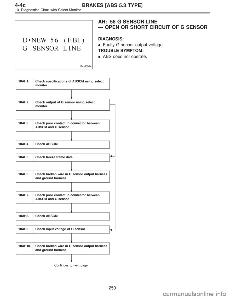
B4M0974
AH: 56 G SENSOR LINE
—OPEN OR SHORT CIRCUIT OF G SENSOR
—
DIAGNOSIS:
�Faulty G sensor output voltage
TROUBLE SYMPTOM:
�ABS does not operate.
10AH1.Check specifications of ABSCM using select
monitor.
�
�
10AH2.Check output of G sensor using select
monitor.
10AH3.Check poor contact in connector between
ABSCM and G sensor.
10AH4.Check ABSCM.
10AH5.Check freeze frame data.
10AH6.Check broken wire in G sensor output harness
and ground harness.
10AH7.Check poor contact in connector between
ABSCM and G sensor.
10AH8.Check ABSCM.
10AH9.Check input voltage of G sensor.
10AH10.Check broken wire in G sensor output harness
and ground harness.
Continues to next page.
�
�
�
�
�
�
�
�
250
4-4cBRAKES [ABS 5.3 TYPE]
10. Diagnostics Chart with Select Monitor
Page 2856 of 3342
From the former page.
10AH11.
Check ground short in G sensor output
harness.
10AH12.Check G sensor.
10AH13.Check poor contact in connector between
ABSCM and G sensor.
10AH14.Check ABSCM.
WIRING DIAGRAM:
B4M1050
�
�
�
�
251
4-4cBRAKES [ABS 5.3 TYPE]
10. Diagnostics Chart with Select Monitor
Page 2857 of 3342
 Press
F,
0and
0on the select monitor.
2) Read the select monitor display.
: Is an ABSCM for 4WD model installed on a
FWD model?
: Re")
B4M0921
10AH1CHECK SPECIFICATIONS OF ABSCM
USING SELECT MONITOR.
1) Press
F,
0and
0on the select monitor.
2) Read the select monitor display.
: Is an ABSCM for 4WD model installed on a
FWD model?
: Replace ABSCM.
: Go to step10AH2.
B4M0927
10AH2CHECK OUTPUT OF G SENSOR USING
SELECT MONITOR.
1) Press
F,
1and
0on the select monitor.
2) Read the select monitor display.
: Is the indicated reading 2.3±0.2 V when the
G sensor is in horizontal position?
: Go to step10AH3.
: Go to step10AH5.
10AH3CHECK POOR CONTACT IN CONNEC-
TOR BETWEEN ABSCM AND G SENSOR.
: Is there poor contact in connector between
ABSCM and G sensor?
: Repair connector.
: Go to step10AH4.
10AH4
CHECK ABSCM.
1) Connect all connectors.
2) Erase the memory.
3) Perform inspection mode.
4) Read out the trouble code.
: Is the same trouble code as in the current
diagnosis still being output?
: Replace ABSCM.
: Go to next.
: Are other trouble codes being output?
: Proceed with the diagnosis corresponding to the
trouble code.
: A temporary poor contact.
252
4-4cBRAKES [ABS 5.3 TYPE]
10. Diagnostics Chart with Select Monitor
Page 2859 of 3342
B4M0912A
10AH6CHECK BROKEN WIRE IN G SENSOR
OUTPUT HARNESS AND GROUND HAR-
NESS.
1) Turn ignition switch to OFF.
2) Disconnect connector from ABSCM.
3) Measure resistance between ABSCM connector termi-
nals.
: Connector & terminal
(P49) No. 7—No. 45
Is resistance 4.6±0.3 kΩ?
: Go to step10AH7.
: Repair harness between G sensor and ABSCM.
10AH7CHECK POOR CONTACT IN CONNEC-
TOR BETWEEN ABSCM AND G SENSOR.
: Is there poor contact in connector between
ABSCM and G sensor?
: Repair connector.
: Go to step10AH8.
10AH8
CHECK ABSCM.
1) Connect all connectors.
2) Erase the memory.
3) Perform inspection mode.
4) Read out the trouble code.
: Is the same trouble code as in the current
diagnosis still being output?
: Replace ABSCM.
: Go to next.
: Are other trouble codes being output?
: Proceed with the diagnosis corresponding to the
trouble code.
: A temporary poor contact.
254
4-4cBRAKES [ABS 5.3 TYPE]
10. Diagnostics Chart with Select Monitor
Page 2860 of 3342
B4M0911B
10AH9
CHECK INPUT VOLTAGE OF G SENSOR.
1) Turn ignition switch to OFF.
2) Remove console box.
3) Disconnect G sensor from body. (Do not disconnect
connector.)
4) Turn ignition switch to ON.
5) Measure voltage between G sensor connector termi-
nals.
: Connector & terminal
(P11) No. 1 (+)—No.3(�)
Is voltage 5±0.25 V?
: Go to step10AH10.
: Repair harness connector between G sensor and
ABSCM.
B4M0912A
10AH10CHECK BROKEN WIRE IN G SENSOR
OUTPUT HARNESS AND GROUND HAR-
NESS.
1) Turn ignition switch to OFF.
2) Disconnect connector from ABSCM.
3) Measure resistance between ABSCM connector termi-
nals.
: Connector & terminal
(P49) No. 7—No. 45
Is resistance 4.6±0.3 kΩ?
: Go to step10AH11.
: Repair harness between G sensor and ABSCM.
255
4-4cBRAKES [ABS 5.3 TYPE]
10. Diagnostics Chart with Select Monitor
 Turn ignition switch to OFF.
2) Remove console cover from console box.
3) Disconnect connector from G sensor.
4) Measure resistance of G senso")

 Turn ignition switch to OFF.
2) Disconnect connector from ABSCM.
3) Measure resistance between ABSCM connector termi")
 Turn ignition switch to OFF.
2) Remove console box.
3) Disconnect G sensor from body. (Do not disconnect
connector.)
4) Turn ignition switch to ON.
5")