Page 98 of 3342
![SUBARU LEGACY 1997 Service Repair Manual
4-4d
[T8W3]
BRAKES
[ABS
5
.3i
TYPE]
8
.
Diagnostics
Chart
with
Trouble
Code
by
ABS
Warning
Light
F49
D
P
V(4)
84M1234AI
F49
1
234,1567
89
1011112113
1
5
161
1
19
2
21
23
242526
728293031
f
1
SUBARU LEGACY 1997 Service Repair Manual
4-4d
[T8W3]
BRAKES
[ABS
5
.3i
TYPE]
8
.
Diagnostics
Chart
with
Trouble
Code
by
ABS
Warning
Light
F49
D
P
V(4)
84M1234AI
F49
1
234,1567
89
1011112113
1
5
161
1
19
2
21
23
242526
728293031
f
1](/manual-img/17/57434/w960_57434-97.png)
4-4d
[T8W3]
BRAKES
[ABS
5
.3i
TYPE]
8
.
Diagnostics
Chart
with
Trouble
Code
by
ABS
Warning
Light
F49
D
P
V(4)
84M1234AI
F49
1
234,1567
89
1011112113
1
5
161
1
19
2
21
23
242526
728293031
f
1
D~
SL
84M
7243A
8W3
CHECK
INPUT
VOLTAGEOF
ABSCM&H/U
.
1)
Run
the
engine
at
idle
.
2)
Measure
voltage
between
ABSCM&H/U
connector
and
chassis
ground
.
Connector
&
terminal
(F49)
No
.
1
(+)
-
Chassis
ground
(
)
:
CHECK
:
is
the
voltage
between
10
V
and
15
V?
Go
tostep
8W4
.
No
:
Repair
harness
connector
between
battery,
igni-
tion
switch
and
ABSCM&H/U
.
8W4
I
CHECK
GROUND
CIRCUIT
OF
ABSCM&H/U
.
I
1)
Turn
ignition
switch
to
OFF
.
2)
Measure
resistance
between
ABSCM&H/U
connector
and
chassis
ground
.
Connector
&
terminal
(F49)
No
.
23
-
Chassis
ground
:
CHECK
:
Is
the
resistance
less
than
0
.5
S2?
~ves~
:
Go
to
step
8WS
.
No
:
Repair
ABSCM&H/U
ground
harness
.
8W5
I
CHECK
MOTOR
OPERATION
.I
Operate
the
sequence
control
<
Ref
.
to
4-4
[W25D1
]
.
>
NOTE
:
Use
the
diagnosis
connector
to
operatethe
sequence
control
.
cHEC~c
:
Can
motor
revolution
noise
{buzz)
be
heard
when
carrying
out
the
sequence
control?
Go
tostep
8W6
.
No
:
Replace
ABSCM&H/U
.
80
Page 246 of 3342

1. Foreword
This chapter describes major inspection and service pro-
cedures for the engine mounted on the body. For proce-
dures not found in this chapter, refer to the service proce-
dure section in the applicable chapter.
2. Ignition Timing
A: MEASUREMENT
1. 2200 cc MODEL
1) Warm-up the engine.
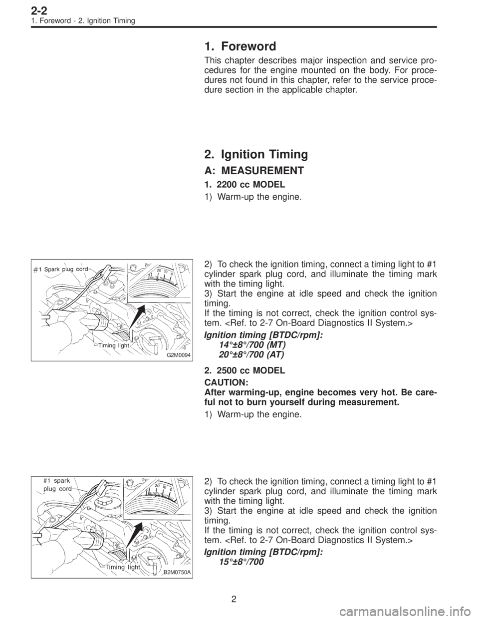
G2M0094
2) To check the ignition timing, connect a timing light to #1
cylinder spark plug cord, and illuminate the timing mark
with the timing light.
3) Start the engine at idle speed and check the ignition
timing.
If the timing is not correct, check the ignition control sys-
tem.
Ignition timing [BTDC/rpm]:
14°±8°/700 (MT)
20°±8°/700 (AT)
2. 2500 cc MODEL
CAUTION:
After warming-up, engine becomes very hot. Be care-
ful not to burn yourself during measurement.
1) Warm-up the engine.
B2M0750A
2) To check the ignition timing, connect a timing light to #1
cylinder spark plug cord, and illuminate the timing mark
with the timing light.
3) Start the engine at idle speed and check the ignition
timing.
If the timing is not correct, check the ignition control sys-
tem.
Ignition timing [BTDC/rpm]:
15°±8°/700
2
2-2
1. Foreword - 2. Ignition Timing
Page 247 of 3342

1. Foreword
This chapter describes major inspection and service pro-
cedures for the engine mounted on the body. For proce-
dures not found in this chapter, refer to the service proce-
dure section in the applicable chapter.
2. Ignition Timing
A: MEASUREMENT
1. 2200 cc MODEL
1) Warm-up the engine.
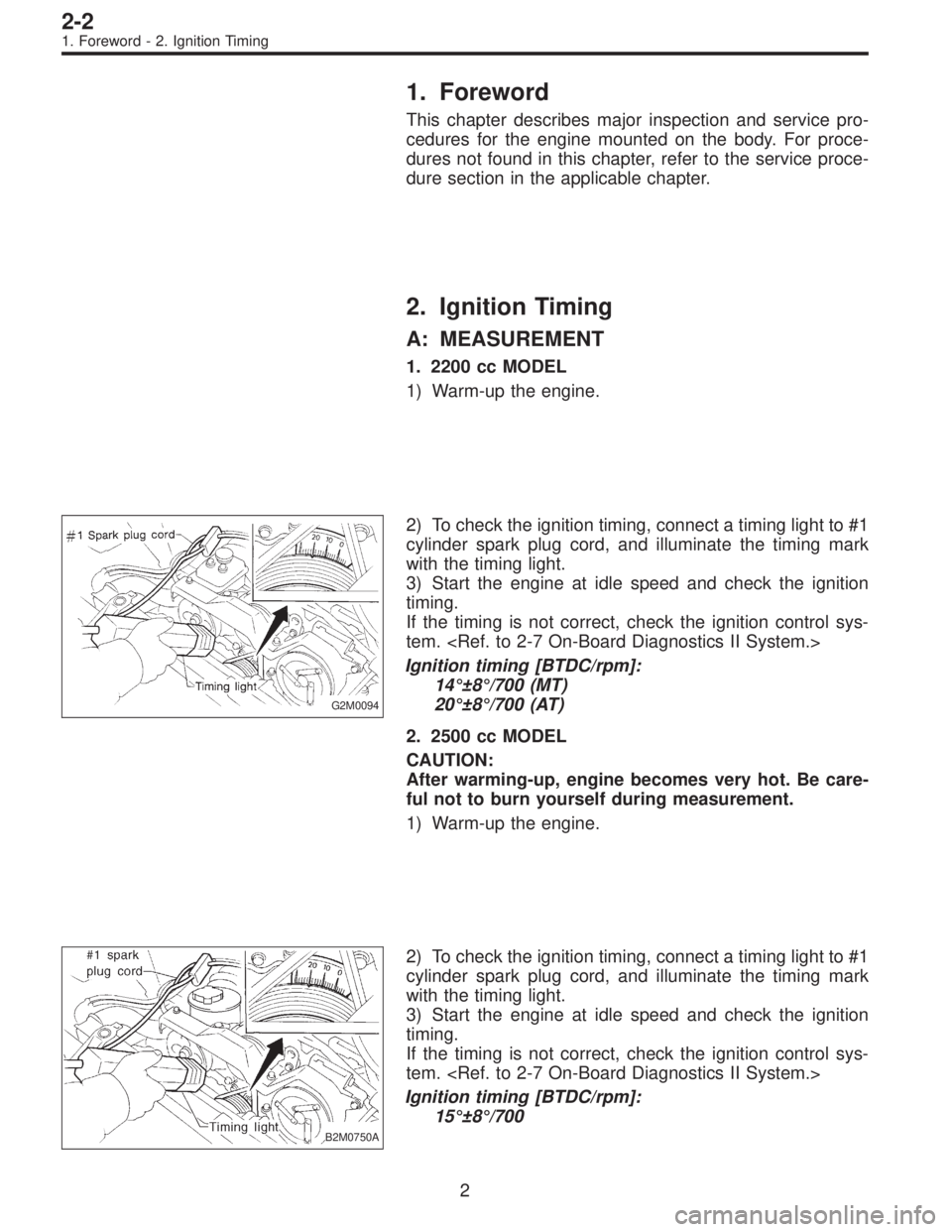
G2M0094
2) To check the ignition timing, connect a timing light to #1
cylinder spark plug cord, and illuminate the timing mark
with the timing light.
3) Start the engine at idle speed and check the ignition
timing.
If the timing is not correct, check the ignition control sys-
tem.
Ignition timing [BTDC/rpm]:
14°±8°/700 (MT)
20°±8°/700 (AT)
2. 2500 cc MODEL
CAUTION:
After warming-up, engine becomes very hot. Be care-
ful not to burn yourself during measurement.
1) Warm-up the engine.
B2M0750A
2) To check the ignition timing, connect a timing light to #1
cylinder spark plug cord, and illuminate the timing mark
with the timing light.
3) Start the engine at idle speed and check the ignition
timing.
If the timing is not correct, check the ignition control sys-
tem.
Ignition timing [BTDC/rpm]:
15°±8°/700
2
2-2
1. Foreword - 2. Ignition Timing
Page 248 of 3342

3. Engine Idle Speed
A: MEASUREMENT
1) Before checking idle speed, check the following:
(1) Ensure that air cleaner element is free from
clogging, ignition timing is correct, spark plugs are in
good condition, and that hoses are connected properly.
(2) Ensure that malfunction indicator light (CHECK
ENGINE light) does not illuminate.
2) Warm-up the engine.
G2M0096
3) Connect Subaru Select Monitor or the OBD-II general
scan tool to data link connector.
CAUTION:
When connecting Subaru Select Monitor, turn ignition
switch to OFF.
4) Start the engine and measure engine speed.
NOTE:
Engine speed is indicated on Subaru Select Monitor by
selecting “MODE F04”.
G2M0097
NOTE:
�When using the OBD-II general scan tool, carefully read
its operation manual.
�When Subaru Select Monitor is not used, attach the
pickup sensor on tachometer (Secondary pickup type) to
#1 cylinder spark plug cord.
�This ignition system provides simultaneous ignition for
#1 and #2 plugs. It must be noted that some tachometers
may register twice that of actual engine speed.
5) Check idle speed when unloaded. (With headlights,
heater fan, rear defroster, radiator fan, air conditioning, etc.
OFF)
Idle speed (No load and gears in neutral (MT) or N or
P (AT) position):
700±100 rpm
6) Check idle speed when loaded. (Turn air conditioning
switch to “ON” and operate compressor for at least one
minute before measurement.)
Idle speed [A/C“ON”, no load and gears in neutral
(MT) or N or P (AT) position]:
850±50 rpm
CAUTION:
Never rotate idle adjusting screw. If idle speed is out
of specifications, refer to General On-board Diagnosis
Table under “2-7 On-Board Diagnostics II System”.
3
2-2
3. Engine Idle Speed
Page 253 of 3342
G2M0093
4) Connect oil pressure gauge hose to cylinder block.
5) Start the engine, and measure oil pressure.
Oil pressure:
98 kPa (1.0 kg/cm
2,14 psi) or more at 800 rpm
294 kPa (3.0 kg/cm2, 43 psi) or more at 5,000 rpm
CAUTION:
�If oil pressure is out of specification, check oil
pump, oil filter and lubrication line.
�If oil pressure warning light is turned ON and oil
pressure is in specification, replace oil pressure
switch.
NOTE:
The specified data is based on an engine oil temperature
of 80°C (176°F).
6) After measuring oil pressure, install oil pressure switch.
Tightening torque:
25±3 N⋅m (2.5±0.3 kg-m, 18.1±2.2 ft-lb)
7) Install generator and V-belt in the reverse order of
removal, and adjust the V-belt deflection.
8
2-2
6. Engine Oil Pressure
Page 306 of 3342
B2M0077A
(6) Check the valve guide protrusion.
Valve guide protrusion: L
17.5—18.0 mm (0.689—0.709 in)
B2M0078
(7) Ream the inside of valve guide with ST. Gently
rotate the reamer clockwise while pressing it lightly into
valve guide, and return it also rotating clockwise. After
reaming, clean valve guide to remove chips.
ST 499767400 VALVE GUIDE REAMER
CAUTION:
�Apply engine oil to the reamer when reaming.
�If the inner surface of the valve guide is torn, the
edge of the reamer should be slightly ground with an
oil stone.
�If the inner surface of the valve guide becomes lus-
trous and the reamer does not chips, use a new reamer
or remedy the reamer.
(8) Recheck the contact condition between valve and
valve seat after replacing valve guide.
43
2-3SERVICE PROCEDURE
6. Cylinder Head
Page 341 of 3342

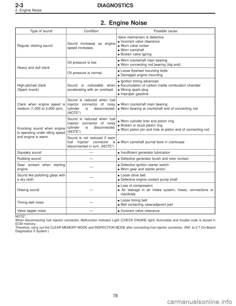
2. Engine Noise
Type of sound Condition Possible cause
Regular clicking soundSound increases as engine
speed increases.Valve mechanism is defective.
�Incorrect valve clearance
�Worn valve rocker
�Worn camshaft
�Broken valve spring
Heavy and dull clankOil pressure is low.�Worn crankshaft main bearing
�Worn connecting rod bearing (big end)
Oil pressure is normal.�Loose flywheel mounting bolts
�Damaged engine mounting
High-pitched clank
(Spark knock)Sound is noticeable when
accelerating with an overload.�Ignition timing advanced
�Accumulation of carbon inside combustion chamber
�Wrong spark plug
�Improper gasoline
Clank when engine speed is
medium (1,000 to 2,000 rpm).Sound is reduced when fuel
injector connector of noisy
cylinder is disconnected.
(NOTE*)�Worn crankshaft main bearing
�Worn bearing at crankshaft end of connecting rod
Knocking sound when engine
is operating under idling speed
and engine is warm.Sound is reduced when fuel
injector connector of noisy
cylinder is disconnected.
(NOTE*)�Worn cylinder liner and piston ring
�Broken or stuck piston ring
�Worn piston pin and hole at piston end of connecting rod
Sound is not reduced if each
fuel injector connector is
disconnected in turn. (NOTE*)�Worn camshaft journal bore in crankcase
Squeaky sound—�Insufficient generator lubrication
Rubbing sound—�Defective generator brush and rotor contact
Gear scream when starting
engine—�Defective ignition starter switch
�Worn gear and starter pinion
Sound like polishing glass with
a dry cloth—�Loose drive belt
�Defective engine coolant pump shaft
Hissing sound—�Loss of compression
�Air leakage in air intake system, hoses, connections or
manifolds
Timing belt noise—�Loose timing belt
�Belt contacting case/adjacent part
Valve tappet noise—�Incorrect valve clearance
NOTE*:
When disconnecting fuel injector connector, Malfunction Indicator Light (CHECK ENGINE light) illuminates and trouble code is stored in
ECM memory.
Therefore, carry out the CLEAR MEMORY MODE and INSPECTION MODE after connecting fuel injector connector. (Ref. to 2-7 On-Board
Diagnostics II System.)
78
2-3DIAGNOSTICS
2. Engine Noise
Page 381 of 3342

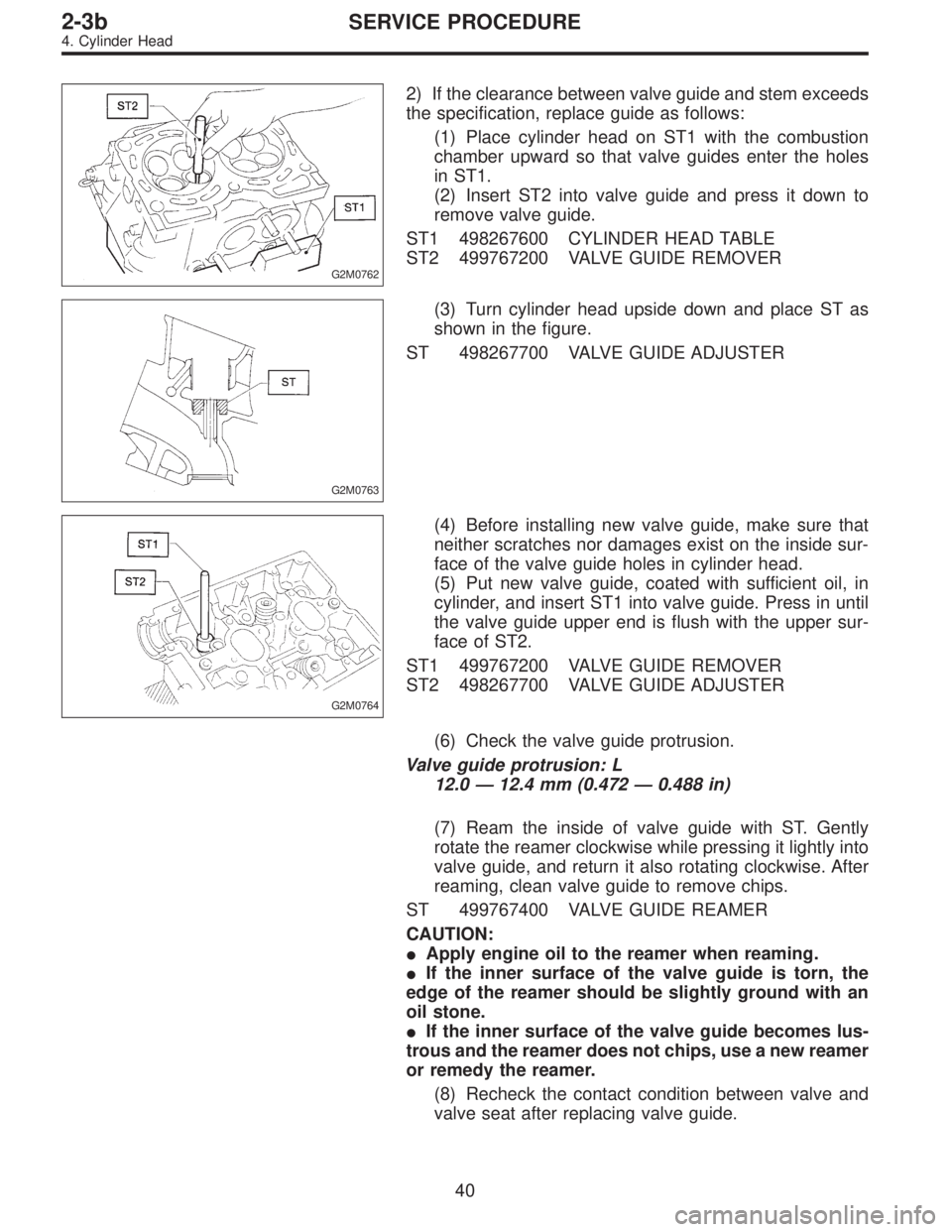
G2M0762
2) If the clearance between valve guide and stem exceeds
the specification, replace guide as follows:
(1) Place cylinder head on ST1 with the combustion
chamber upward so that valve guides enter the holes
in ST1.
(2) Insert ST2 into valve guide and press it down to
remove valve guide.
ST1 498267600 CYLINDER HEAD TABLE
ST2 499767200 VALVE GUIDE REMOVER
G2M0763
(3) Turn cylinder head upside down and place ST as
shown in the figure.
ST 498267700 VALVE GUIDE ADJUSTER
G2M0764
(4) Before installing new valve guide, make sure that
neither scratches nor damages exist on the inside sur-
face of the valve guide holes in cylinder head.
(5) Put new valve guide, coated with sufficient oil, in
cylinder, and insert ST1 into valve guide. Press in until
the valve guide upper end is flush with the upper sur-
face of ST2.
ST1 499767200 VALVE GUIDE REMOVER
ST2 498267700 VALVE GUIDE ADJUSTER
(6) Check the valve guide protrusion.
Valve guide protrusion: L
12.0—12.4 mm (0.472—0.488 in)
(7) Ream the inside of valve guide with ST. Gently
rotate the reamer clockwise while pressing it lightly into
valve guide, and return it also rotating clockwise. After
reaming, clean valve guide to remove chips.
ST 499767400 VALVE GUIDE REAMER
CAUTION:
�Apply engine oil to the reamer when reaming.
�If the inner surface of the valve guide is torn, the
edge of the reamer should be slightly ground with an
oil stone.
�If the inner surface of the valve guide becomes lus-
trous and the reamer does not chips, use a new reamer
or remedy the reamer.
(8) Recheck the contact condition between valve and
valve seat after replacing valve guide.
40
2-3bSERVICE PROCEDURE
4. Cylinder Head