Page 1355 of 3342
G4M0444
7) Remove tone wheel while removing hub from housing
and hub assembly.
CAUTION:
Be careful not to damage teeth faces of tone wheel
during removal.
2. REAR ABS SENSOR
1) Remove rear seat and disconnect rear ABS sensor con-
nector.
2) Remove rear sensor harness bracket from rear trailing
link and bracket.
G4M0445
3) Remove rear ABS sensor from rear back plate.
4) Remove rear tone wheel while removing hub from
housing and hub assembly.
CAUTION:
�Be careful not to damage pole piece located at tip of
the sensor and teeth faces during removal.
�Do not pull sensor harness during removal.
B: INSPECTION
1. ABS SENSOR
1) Check pole piece of ABS sensor for foreign particles or
damage. If necessary, clean pole piece or replace ABS
sensor.
73
4-4SERVICE PROCEDURE
14. ABS Sensor
Page 1356 of 3342
B4M0248
2) Measure ABS sensor resistance.
ABS sensor Terminal No. Standard
Front - LH 1 and 2
1.0±0.2 kΩ Front - RH 1 and 2
Rear - LH 1 and 2
Rear - RH 1 and 2
CAUTION:
If resistance is outside the standard value, replace
ABS sensor with new one.
NOTE:
Check ABS sensor cable for discontinuity. If necessary,
replace with a new one.
G4M0448
2. TONE WHEEL
1) Check tone wheel’s teeth (44 pieces) for cracks or
dents. If necessary, replace tone wheel with a new one.
2) Clearances (sensor gaps) should be measured one by
one to ensure tone wheel and speed sensor are installed
correctly.
ABS sensor clearance:
Front
0.9—1.4 mm (0.035—0.055 in)
Rear
0.7—1.2 mm (0.028—0.047 in)
NOTE:
�If clearance is narrow, adjust by using spacer (Part No.
26755AA000).
�If clearance is wide, check the outputted voltage then
replace ABS sensor or tone wheel if the outputted voltage
is outside the specification.
74
4-4SERVICE PROCEDURE
14. ABS Sensor
Page 1357 of 3342
B4M0118B
3. OUTPUT VOLTAGE
Output voltage can be checked by the following method.
Install resistor and condenser, then rotate wheel about 2.75
km/h (2 MPH) or equivalent.
NOTE:
Regarding terminal No., please refer to item 1. ABS SEN-
SOR.
C: INSTALLATION
1. FRONT ABS SENSOR
1) Install tone wheel on hub, then install housing on hub
assembly.
G4M0443
2) Temporarily install front ABS sensor on housing.
CAUTION:
Be careful not to strike ABS sensor’s pole piece and
tone wheel’s teeth against adjacent metal parts during
installation.
3) Install front drive shaft to hub spline.
[W1E0].>
75
4-4SERVICE PROCEDURE
14. ABS Sensor
Page 1358 of 3342
G4M0451
4) Install front ABS sensor on strut and wheel apron
bracket.
Tightening torque:
32±10 N⋅m (3.3±1.0 kg-m, 24±7 ft-lb)
5) Place a thickness gauge between ABS sensor’s pole
piece and tone wheel’s tooth face. After standard clearance
is obtained over the entire perimeter, tighten ABS sensor
on housing to specified torque.
ABS sensor standard clearance:
0.9—1.4 mm (0.035—0.055 in)
Tightening torque:
32±10 N⋅m (3.3±1.0 kg-m, 24±7 ft-lb)
CAUTION:
Check the marks on the harness to make sure that no
distortion exists. (RH: white, LH: yellow)
NOTE:
If the clearance is outside specifications, readjust.
2. REAR ABS SENSOR
1) Install rear tone wheel on hub, then rear housing on
hub.
G4M0445
2) Temporarily install rear ABS sensor on back plate.
CAUTION:
Be careful not to strike ABS sensor’s pole piece and
tone wheel’s teeth against adjacent metal parts during
installation.
76
4-4SERVICE PROCEDURE
14. ABS Sensor
Page 1359 of 3342
3) Install rear drive shaft to rear housing and rear differen-
tial spindle.
G4M0453
4) Install rear sensor harness on rear trailing link.
Tightening torque:
32±10 N⋅m (3.3±1.0 kg-m, 24±7 ft-lb)
5) Place a thickness gauge between ABS sensor’s pole
piece and tone wheel’s tooth face. After standard clearance
is obtained over the entire perimeter, tighten ABS sensor
on back plate to specified torque.
ABS sensor standard clearance:
0.7—1.2 mm (0.028—0.047 in)
Tightening torque:
32±10 N⋅m (3.3±1.0 kg-m, 24±7 ft-lb)
CAUTION:
Check the marks on the harness to make sure that no
distortion exists. (RH: white, LH: yellow)
NOTE:
If the clearance is outside specifications, readjust.
77
4-4SERVICE PROCEDURE
14. ABS Sensor
Page 1360 of 3342
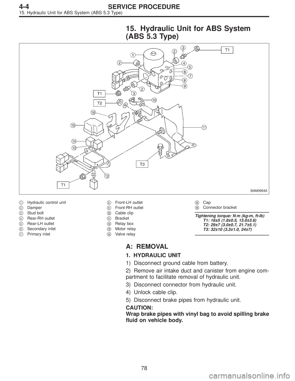
15. Hydraulic Unit for ABS System
(ABS 5.3 Type)
B4M0994A
�1Hydraulic control unit
�
2Damper
�
3Stud bolt
�
4Rear-RH outlet
�
5Rear-LH outlet
�
6Secondary inlet
�
7Primary inlet�
8Front-LH outlet
�
9Front-RH outlet
�
10Cable clip
�
11Bracket
�
12Relay box
�
13Motor relay
�
14Valve relay�
15Cap
�
16Connector bracket
Tightening torque: N⋅m (kg-m, ft-lb)
T1: 18±5 (1.8±0.5, 13.0±3.6)
T2: 29±7 (3.0±0.7, 21.7±5.1)
T3: 32±10 (3.3±1.0, 24±7)
A: REMOVAL
1. HYDRAULIC UNIT
1) Disconnect ground cable from battery.
2) Remove air intake duct and canister from engine com-
partment to facilitate removal of hydraulic unit.
3) Disconnect connector from hydraulic unit.
4) Unlock cable clip.
5) Disconnect brake pipes from hydraulic unit.
CAUTION:
Wrap brake pipes with vinyl bag to avoid spilling brake
fluid on vehicle body.
78
4-4SERVICE PROCEDURE
15. Hydraulic Unit for ABS System (ABS 5.3 Type)
Page 1361 of 3342
 Remove nuts and bolt which secure hydraulic unit
bracket, and remove hydraulic unit from engine compart-
ment.
CAUTION:
�Hydraulic unit cannot be disassembled. Do not
attempt to loosen bolt")
B4M0996
6) Remove nuts and bolt which secure hydraulic unit
bracket, and remove hydraulic unit from engine compart-
ment.
CAUTION:
�Hydraulic unit cannot be disassembled. Do not
attempt to loosen bolts and nuts.
�Do not drop or bump hydraulic unit.
�Do not turn the hydraulic unit upside down or place
it on its side.
�Be careful to prevent foreign particles from getting
into hydraulic unit.
�When a new hydraulic unit is installed, apply a coat
of rust-preventive wax (Nippeco LT or GB) to bracket
attaching bolt after tightening.
�Do not pull harness disconnecting harness connec-
tor.
2. RELAY BOX
1) Disconnect ground cable from battery.
2) Remove air intake duct and canister from engine com-
partment to facilitate removal of relay box.
B4M1029
3) Disconnect connector from relay box.
4) Unlock cable clip.
5) Remove nuts which secure relay box, and remove relay
box and connector bracket.
CAUTION:
Do not drop or bump relay box.
79
4-4SERVICE PROCEDURE
15. Hydraulic Unit for ABS System (ABS 5.3 Type)
Page 1362 of 3342
 Check connected and fixed condition of connector.
2) Check valve relay and motor relay for discontinuity or
short circuits.
Condition Terminal number Standard Diagram Terminal locatio")
B: INSPECTION
1) Check connected and fixed condition of connector.
2) Check valve relay and motor relay for discontinuity or
short circuits.
Condition Terminal number Standard Diagram Terminal location
Valve relayTurning off
electricity.85—86 103±10Ω
G4M0456G4M0457
30—87a less than 0.5Ω
30—87 less than 1 MΩ
Turning on
electricity between
85 and 86.
(DC 12 V)30—87a more than 1 MΩ
30—87 less than 0.5Ω
Motor relayTurning off
electricity.85—86 80±8Ω
G4M0458G4M0459
30—87 more than 1 MΩ
Turning on
electricity between
85 and 86.
(DC 12 V)30—87 less than 0.5Ω
C: CHECKING THE HYDRAULIC UNIT ABS
OPERATION
1. CHECKING THE HYDRAULIC UNIT ABS
OPERATION BY PRESSURE GAUGE
1) Lift-up vehicle and remove wheels.
2) Disconnect the air bleeder screws from the FL and FR
caliper bodies.
B4M0633A
3) Connect two pressure gauges to the FL and FR caliper
bodies.
CAUTION:
�Pressure gauges used exclusively for brake fluid
must be used.
�Do not employ pressure gauge previously used for
transmission since the piston seal is expanded which
may lead to malfunction of the brake.
NOTE:
Wrap sealing tape around the pressure gauge.
80
4-4SERVICE PROCEDURE
15. Hydraulic Unit for ABS System (ABS 5.3 Type)
![SUBARU LEGACY 1997 Service Repair Manual G4M0444
7) Remove tone wheel while removing hub from housing
and hub assembly. <Ref. to 4-2 [W1B0].>
CAUTION:
Be careful not to damage teeth faces of tone wheel
during removal.
2. REAR ABS SENSOR
1) R](/manual-img/17/57434/w960_57434-1354.png "SUBARU LEGACY 1997 Service Repair Manual G4M0444
7) Remove tone wheel while removing hub from housing
and hub assembly. <Ref. to 4-2 [W1B0].>
CAUTION:
Be careful not to damage teeth faces of tone wheel
during removal.
2. REAR ABS SENSOR
1) R")
 Measure ABS sensor resistance.
ABS sensor Terminal No. Standard
Front - LH 1 and 2
1.0±0.2 kΩ Front - RH 1 and 2
Rear - LH 1 and 2
Rear - RH 1 and 2
CAUTION:
If resistance is outside the")
 or equivalent.
NOTE:
Regarding terminal No.,")
 Install front ABS sensor on strut and wheel apron
bracket.
Tightening torque:
32±10 N⋅m (3.3±1.0 kg-m, 24±7 ft-lb)
5) Place a thickness gauge between ABS sensor’s pole
piece and tone")
![SUBARU LEGACY 1997 Service Repair Manual 3) Install rear drive shaft to rear housing and rear differen-
tial spindle. <Ref. to 4-2 [W2E0].>
G4M0453
4) Install rear sensor harness on rear trailing link.
Tightening torque:
32±10 N⋅m (3.3±1](/manual-img/17/57434/w960_57434-1358.png "SUBARU LEGACY 1997 Service Repair Manual 3) Install rear drive shaft to rear housing and rear differen-
tial spindle. <Ref. to 4-2 [W2E0].>
G4M0453
4) Install rear sensor harness on rear trailing link.
Tightening torque:
32±10 N⋅m (3.3±1")