Page 1783 of 2053

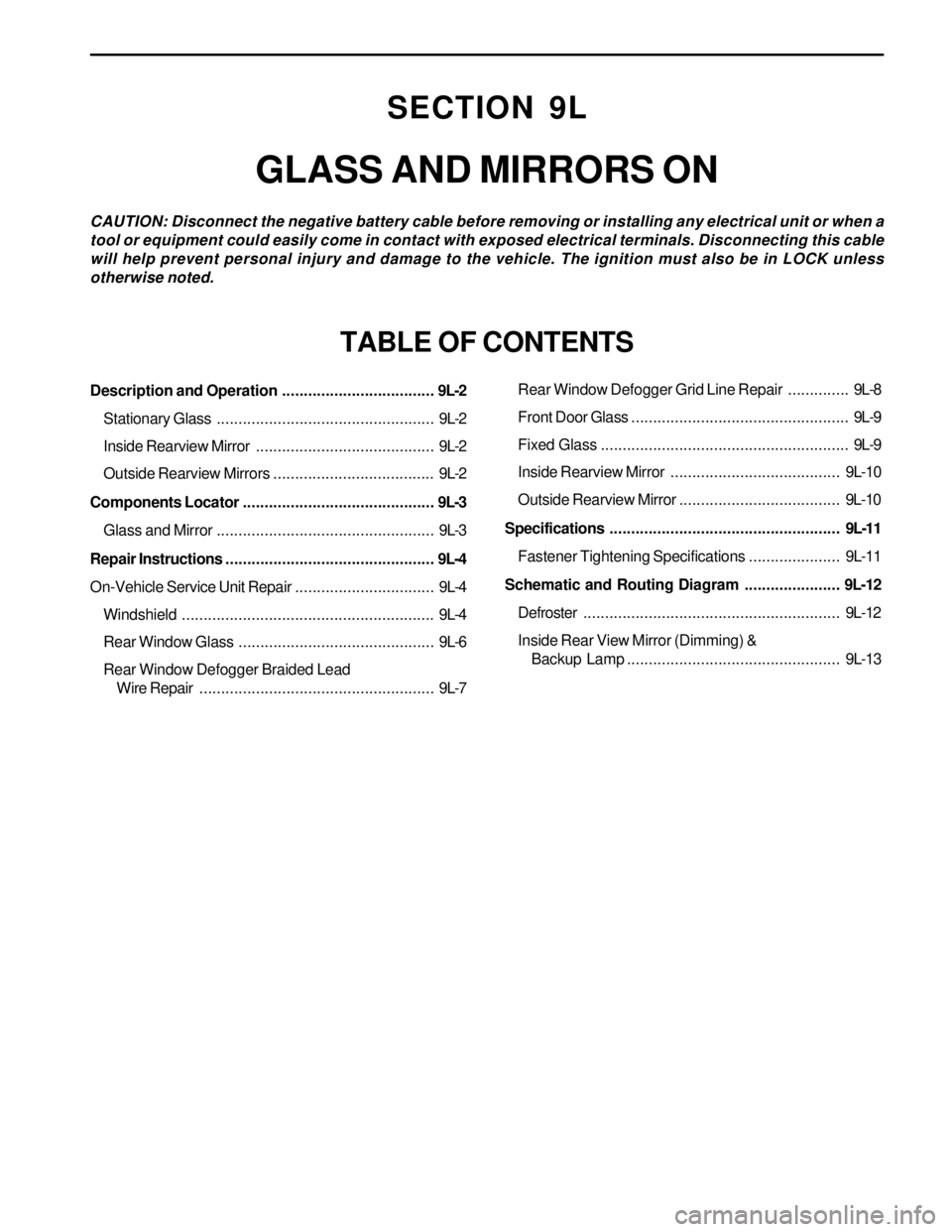
SECTION 9L
GLASS AND MIRRORS ON
CAUTION: Disconnect the negative battery cable before removing or installing any electrical unit or when a
tool or equipment could easily come in contact with exposed electrical terminals. Disconnecting this cable
will help prevent personal injury and damage to the vehicle. The ignition must also be in LOCK unless
otherwise noted.
TABLE OF CONTENTS
Description and Operation...................................9L-2
Stationary Glass..................................................9L-2
Inside Rearview Mirror.........................................9L-2
Outside Rearview Mirrors.....................................9L-2
Components Locator............................................9L-3
Glass and Mirror..................................................9L-3
Repair Instructions................................................9L-4
On-Vehicle Service Unit Repair................................9L-4
Windshield..........................................................9L-4
Rear Window Glass.............................................9L-6
Rear Window Defogger Braided Lead
Wire Repair......................................................9L-7Rear Window Defogger Grid Line Repair..............9L-8
Front Door Glass..................................................9L-9
Fixed Glass.........................................................9L-9
Inside Rearview Mirror ....................................... 9L-10
Outside Rearview Mirror..................................... 9L-10
Specifications.....................................................9L-11
Fastener Tightening Specifications..................... 9L-11
Schematic and Routing Diagram......................9L-12
Defroster........................................................... 9L-12
Inside Rear View Mirror (Dimming) &
Backup Lamp................................................. 9L-13
Page 1794 of 2053
SSANGYONG MY2002
9L-12 GLASS AND MIRRORS
SCHEMATIC AND ROUTING DIAGRAMS
DEFROSTER
KAA9L210
Page 1819 of 2053

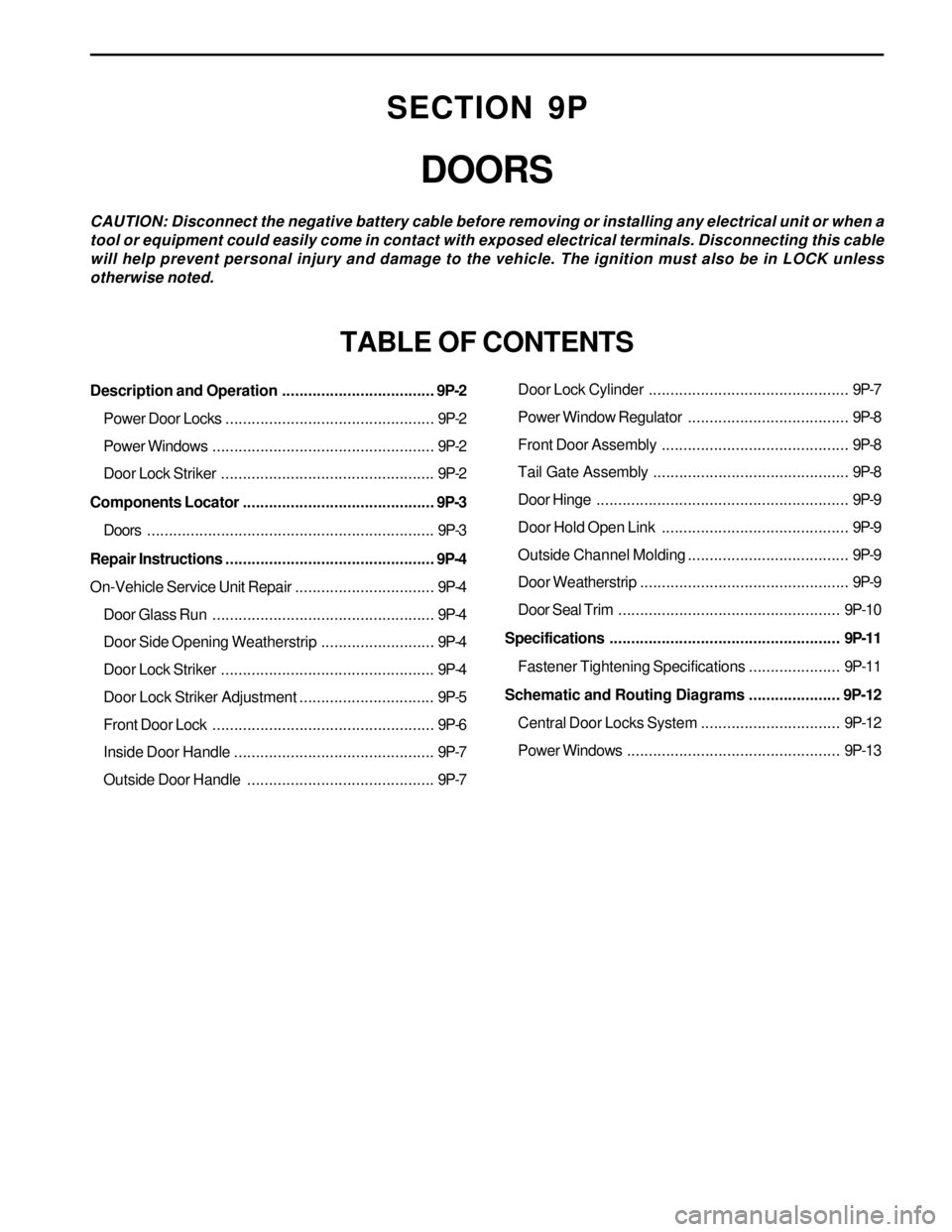
SECTION 9P
DOORS
CAUTION: Disconnect the negative battery cable before removing or installing any electrical unit or when a
tool or equipment could easily come in contact with exposed electrical terminals. Disconnecting this cable
will help prevent personal injury and damage to the vehicle. The ignition must also be in LOCK unless
otherwise noted.
TABLE OF CONTENTS
Description and Operation...................................9P-2
Power Door Locks................................................9P-2
Power Windows...................................................9P-2
Door Lock Striker.................................................9P-2
Components Locator............................................9P-3
Doors ..................................................................9P-3
Repair Instructions................................................9P-4
On-Vehicle Service Unit Repair................................9P-4
Door Glass Run...................................................9P-4
Door Side Opening Weatherstrip..........................9P-4
Door Lock Striker.................................................9P-4
Door Lock Striker Adjustment...............................9P-5
Front Door Lock...................................................9P-6
Inside Door Handle..............................................9P-7
Outside Door Handle ...........................................9P-7Door Lock Cylinder..............................................9P-7
Power Window Regulator.....................................9P-8
Front Door Assembly ...........................................9P-8
Tail Gate Assembly.............................................9P-8
Door Hinge..........................................................9P-9
Door Hold Open Link ...........................................9P-9
Outside Channel Molding.....................................9P-9
Door Weatherstrip................................................9P-9
Door Seal Trim...................................................9P-10
Specifications.....................................................9P-11
Fastener Tightening Specifications.....................9P-11
Schematic and Routing Diagrams.....................9P-12
Central Door Locks System................................9P-12
Power Windows.................................................9P-13
Page 1829 of 2053
SSANGYONG MY2002
9P-12 DOORS
SCHEMATIC AND ROUTING DIAGRAMS
CENTER DOOR LOCK SYSTEM
KAA9P170
Page 1848 of 2053

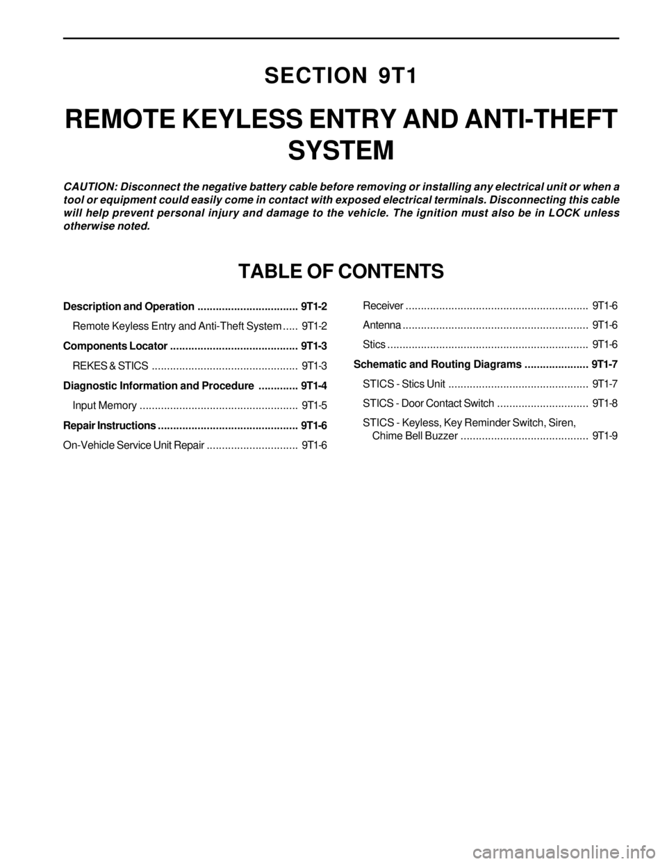
SECTION 9T1
REMOTE KEYLESS ENTRY AND ANTI-THEFT
SYSTEM
CAUTION: Disconnect the negative battery cable before removing or installing any electrical unit or when a
tool or equipment could easily come in contact with exposed electrical terminals. Disconnecting this cable
will help prevent personal injury and damage to the vehicle. The ignition must also be in LOCK unless
otherwise noted.
TABLE OF CONTENTS
Description and Operation.................................9T1-2
Remote Keyless Entry and Anti-Theft System.....9T1-2
Components Locator..........................................9T1-3
REKES & STICS................................................9T1-3
Diagnostic Information and Procedure.............9T1-4
Input Memory....................................................9T1-5
Repair Instructions..............................................9T1-6
On-Vehicle Service Unit Repair..............................9T1-6Receiver............................................................9T1-6
Antenna.............................................................9T1-6
Stics..................................................................9T1-6
Schematic and Routing Diagrams.....................9T1-7
STICS - Stics Unit..............................................9T1-7
STICS - Door Contact Switch..............................9T1-8
STICS - Keyless, Key Reminder Switch, Siren,
Chime Bell Buzzer ..........................................9T1-9
Page 1854 of 2053
REMOTE KEYLESS ENTRY AND ANTI-THEFT SYSTEM 9T1-7
SSANGYONG MY2002
SCHEMATIC AND ROUTING DIAGRAMS
STICS - STICS UNIT
KAA9T070
Page 1857 of 2053
SECTION 9T2
IMMOBILIZER SYSTEM
CAUTION: Disconnect the negative battery cable before removing or installing any electrical unit or when a
tool or equipment could easily come in contact with exposed electrical terminals. Disconnecting this cable
will help prevent personal injury and damage to the vehicle. The ignition must also be in LOCK unless
otherwise noted.
TABLE OF CONTENTS
Description and Operation.................................9T2-2
Components Locator..........................................9T2-3
Immobilizer System...........................................9T2-3
Repair Instructions..............................................9T2-4
On-Vehicle Service Unit Repair..............................9T2-4Immobilizer Antenna ..........................................9T2-4
Transponder Replacement.................................9T2-4
Schematic and Routing Diagrams.....................9T2-5
Immobilizer System (Diesel : Vod).....................9T2-5
Page 1861 of 2053
IMMOBILIZER SYSTEM 9T2-5
SSANGYONG MY2002
SCHEMATIC AND ROUTING DIAGRAMS
IMMOBILIZER SYSTEM (DIESEL : VOD)
KAA9T140