1997 SSANGYONG KORANDO diagram
[x] Cancel search: diagramPage 1303 of 2053

5A-208 AUTOMATIC TRANSMISSION
SSANGYONG MY2002
TCM WIRING DIAGRAM (DIESEL ENGINE - 1 OF 2)
YAD5A230
Page 1304 of 2053

AUTOMATIC TRANSMISSION 5A-209
SSANGYONG MY2002
TCM WIRING DIAGRAM (DIESEL ENGINE - 2 OF 2)
YAD5A240
Page 1372 of 2053
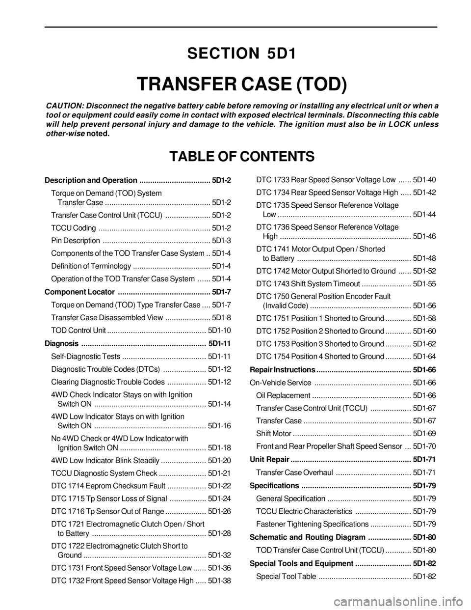
SECTION 5D1
TRANSFER CASE (TOD)
CAUTION: Disconnect the negative battery cable before removing or installing any electrical unit or when a
tool or equipment could easily come in contact with exposed electrical terminals. Disconnecting this cable
will help prevent personal injury and damage to the vehicle. The ignition must also be in LOCK unless
other-wise noted.
TABLE OF CONTENTS
Description and Operation.................................5D1-2
Torque on Demand (TOD) System
Transfer Case.................................................5D1-2
Transfer Case Control Unit (TCCU).....................5D1-2
TCCU Coding....................................................5D1-2
Pin Description..................................................5D1-3
Components of the TOD Transfer Case System ..5D1-4
Definition of Terminology....................................5D1-4
Operation of the TOD Transfer Case System......5D1-4
Component Locator...........................................5D1-7
Torque on Demand (TOD) Type Transfer Case....5D1-7
Transfer Case Disassembled View.....................5D1-8
TOD Control Unit..............................................5D1-10
Diagnosis..........................................................5D1-11
Self-Diagnostic Tests.......................................5D1-11
Diagnostic Trouble Codes (DTCs)....................5D1-12
Clearing Diagnostic Trouble Codes..................5D1-12
4WD Check Indicator Stays on with Ignition
Switch ON....................................................5D1-14
4WD Low Indicator Stays on with Ignition
Switch ON....................................................5D1-16
No 4WD Check or 4WD Low Indicator with
Ignition Switch ON........................................5D1-18
4WD Low Indicator Blink Steadily.....................5D1-20
TCCU Diagnostic System Check......................5D1-21
DTC 1714 Eeprom Checksum Fault..................5D1-22
DTC 1715 Tp Sensor Loss of Signal.................5D1-24
DTC 1716 Tp Sensor Out of Range...................5D1-26
DTC 1721 Electromagnetic Clutch Open / Short
to Battery.....................................................5D1-28
DTC 1722 Electromagnetic Clutch Short to
Ground.........................................................5D1-32
DTC 1731 Front Speed Sensor Voltage Low......5D1-36
DTC 1732 Front Speed Sensor Voltage High.....5D1-38DTC 1733 Rear Speed Sensor Voltage Low......5D1-40
DTC 1734 Rear Speed Sensor Voltage High.....5D1-42
DTC 1735 Speed Sensor Reference Voltage
Low ..............................................................5D1-44
DTC 1736 Speed Sensor Reference Voltage
High.............................................................5D1-46
DTC 1741 Motor Output Open / Shorted
to Battery.....................................................5D1-48
DTC 1742 Motor Output Shorted to Ground......5D1-52
DTC 1743 Shift System Timeout.......................5D1-55
DTC 1750 General Position Encoder Fault
(Invalid Code)...............................................5D1-56
DTC 1751 Position 1 Shorted to Ground............5D1-58
DTC 1752 Position 2 Shorted to Ground............5D1-60
DTC 1753 Position 3 Shorted to Ground............5D1-62
DTC 1754 Position 4 Shorted to Ground............5D1-64
Repair Instructions............................................5D1-66
On-Vehicle Service.............................................5D1-66
Oil Replacement..............................................5D1-66
Transfer Case Control Unit (TCCU)...................5D1-67
Transfer Case..................................................5D1-67
Shift Motor.......................................................5D1-69
Front and Rear Propeller Shaft Speed Sensor ...5D1-70
Unit Repair........................................................5D1-71
Transfer Case Overhaul...................................5D1-71
Specifications...................................................5D1-79
General Specification.......................................5D1-79
TCCU Electric Characteristics..........................5D1-79
Fastener Tightening Specifications...................5D1-79
Schematic and Routing Diagram....................5D1-80
TOD Transfer Case Control Unit (TCCU)............5D1-80
Special Tools and Equipment..........................5D1-82
Special Tool Table ...........................................5D1-82
Page 1401 of 2053
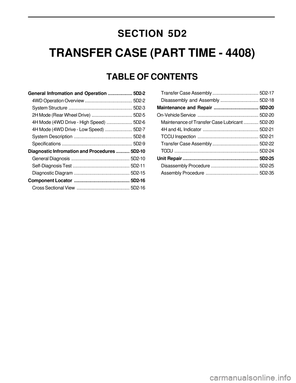
SECTION 5D2
TRANSFER CASE (PART TIME - 4408)
TABLE OF CONTENTS
General Infromation and Operation..................5D2-2
4WD Operation Overview...................................5D2-2
System Structure...............................................5D2-3
2H Mode (Rear Wheel Drive)..............................5D2-5
4H Mode (4WD Drive - High Speed)...................5D2-6
4H Mode (4WD Drive - Low Speed)....................5D2-7
System Description...........................................5D2-8
Specifications....................................................5D2-9
Diagnostic Infromation and Procedures..........5D2-10
General Diagnosis...........................................5D2-10
Self-Diagnosis Test..........................................5D2-11
Diagnostic Diagram .........................................5D2-15
Component Locator .........................................5D2-16
Cross Sectional View.......................................5D2-16Transfer Case Assembly..................................5D2-17
Disassembly and Assembly............................5D2-18
Maintenance and Repair.................................5D2-20
On-Vehicle Service.............................................5D2-20
Maintenance of Transfer Case Lubricant...........5D2-20
4H and 4L Indicator .........................................5D2-21
TCCU Inspection.............................................5D2-21
Transfer Case Assembly..................................5D2-22
TCCU..............................................................5D2-24
Unit Repair........................................................5D2-25
Disassembly Procedure...................................5D2-25
Assembly Procedure.......................................5D2-35
Page 1502 of 2053
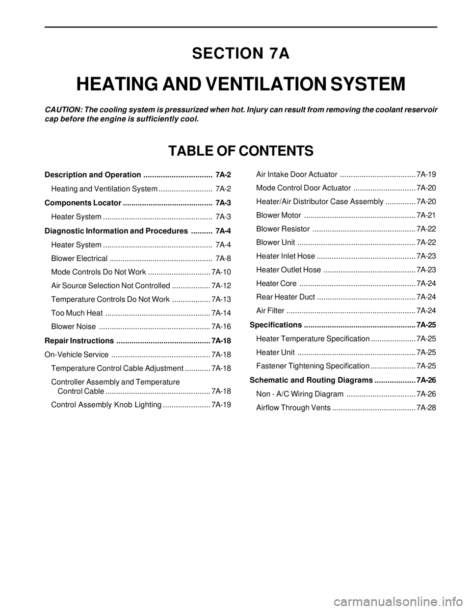
SECTION 7A
HEATING AND VENTILATION SYSTEM
CAUTION: The cooling system is pressurized when hot. Injury can result from removing the coolant reservoir
cap before the engine is sufficiently cool.
TABLE OF CONTENTS
Description and Operation ................................7A-2
Heating and Ventilation System .........................7A-2
Components Locator ..........................................7A-3
Heater System ...................................................7A-3
Diagnostic Information and Procedures ..........7A-4
Heater System ...................................................7A-4
Blower Electrical ................................................7A-8
Mode Controls Do Not Work .............................7A-10
Air Source Selection Not Controlled ..................7A-12
Temperature Controls Do Not Work ..................7A-13
Too Much Heat .................................................7A-14
Blower Noise ....................................................7A-16
Repair Instructions ............................................7A-18
On-Vehicle Service..............................................7A-18
Temperature Control Cable Adjustment ............7A-18
Controller Assembly and Temperature
Control Cable .................................................7A-18
Control Assembly Knob Lighting ......................7A-19Air Intake Door Actuator ...................................7A-19
Mode Control Door Actuator .............................7A-20
Heater/Air Distributor Case Assembly ..............7A-20
Blower Motor ....................................................7A-21
Blower Resistor ................................................7A-22
Blower Unit .......................................................7A-22
Heater Inlet Hose ..............................................7A-23
Heater Outlet Hose ...........................................7A-23
Heater Core......................................................7A-24
Rear Heater Duct ..............................................7A-24
Air Filter ............................................................7A-24
Specifications .................................................... 7A-25
Heater Temperature Specification .....................7A-25
Heater Unit .......................................................7A-25
Fastener Tightening Specification .....................7A-25
Schematic and Routing Diagrams ................... 7A-26
Non - A/C Wiring Diagram ................................7A-26
Airflow Through Vents .......................................7A-28
Page 1509 of 2053
SSANGYONG MY2002
7A-8 HEATING AND VENTILATION SYSTEM
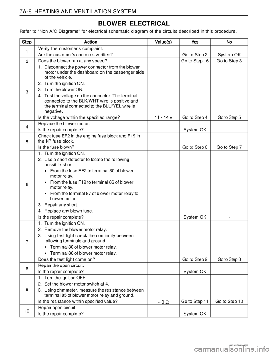
BLOWER ELECTRICAL
Refer to “Non A/C Diagrams” for electrical schematic diagram of the circuits described in this procedure.
Step
1
2
3
4
5
6
7
8
9
10
Action
Verify the customer’s complaint.
Are the customer’s concerns verified?
Does the blower run at any speed?
1. Disconnect the power connector from the blower
motor under the dashboard on the passenger side
of the vehicle.
2. Turn the ignition ON.
3. Turn the blower ON.
4. Test the voltage on the connector. The terminal
connected to the BLK/WHT wire is positive and
the terminal connected to the BLU/YEL wire is
negative.
Is the voltage within the specified range?
Replace the blower motor.
Is the repair complete?
Check fuse EF2 in the engine fuse block and F19 in
the I/P fuse block.
Is the fuse blown?
1. Turn the ignition ON.
2. Use a short detector to locate the following
possible short:
From the fuse EF2 to terminal 30 of blower
motor relay.
From the fuse F19 to terminal 86 of blower
motor relay.
From the terminal 87 of blower motor relay to
blower motor.
3. Repair any short.
4. Replace any blown fuse.
Is the repair complete?
1. Turn the ignition ON.
2. Remove the blower motor relay.
3. Using test light check the continuity between
following terminals and ground:
Terminal 30 of blower motor relay.
Terminal 86 of blower motor relay.
Does the test light come on?
Repair the open circuit.
Is the repair complete?
1. Turn the ignition OFF.
2. Set the blower motor switch at 4.
3. Using ohmmeter, measure the resistance between
terminal 85 of blower motor relay and ground.
Is the resistance within specified value?
Repair open circuit.
Is the repair complete?Yes
Go to Step 2
Go to Step 16
Go to Step 4
System OK
Go to Step 6
System OK
Go to Step 9
System OK
Go to Step 11
System OKNo
System OK
Go to Step 3
Go to Step 5
-
Go to Step 7
-
Go to Step 8
-
Go to Step 10
-
Value(s)
-
11 - 14 v
≈ 0 Ω
Page 1511 of 2053
SSANGYONG MY2002
7A-10 HEATING AND VENTILATION SYSTEM
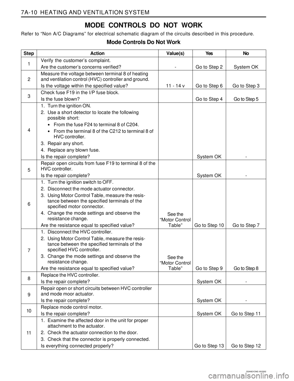
MODE CONTROLS DO NOT WORK
Refer to “Non A/C Diagrams” for electrical schematic diagram of the circuits described in this procedure.
Mode Controls Do Not Work
Step
1
2
3
4
5
6
7
8
9
10
11Action
Verify the customer’s complaint.
Are the customer’s concerns verified?
Measure the voltage between terminal 8 of heating
and ventilation control (HVC) controller and ground.
Is the voltage within the specified value?
Check fuse F19 in the I/P fuse block.
Is the fuse blown?
1. Turn the ignition ON.
2. Use a short detector to locate the following
possible short:
From the fuse F24 to terminal 8 of C204.
From the terminal 8 of the C212 to terminal 8 of
HVC controller.
3. Repair any short.
4. Replace any blown fuse.
Is the repair complete?
Repair open circuits from fuse F19 to terminal 8 of the
HVC controller.
Is the repair complete?
1. Turn the ignition switch to OFF.
2. Disconnect the mode actuator connector.
3. Using Motor Control Table, measure the resis-
tance between the specified terminals of the
specified motor connector.
4. Change the mode settings and observe the
resistance change.
Are the resistance equal to specified value?
1. Disconnect the HVC controller.
2. Using Motor Control Table, measure the resis-
tance between the specified terminals of the
specified HVC controller.
3. Change the mode settings and observe the
resistance change.
Are the resistance equal to specified value?
Replace the HVC controller.
Is the repair complete?
Repair open or short circuits between HVC controller
and mode moor actuator.
Is the repair complete?
Replace mode control motor.
Is the repair complete?
1. Examine the affected door in the unit for proper
attachment to the actuator.
2. Check the actuator connection to the door.
3. Check that the connector is properly connected.
Is everything connected properly?Yes
Go to Step 2
Go to Step 6
Go to Step 4
System OK
System OK
Go to Step 10
Go to Step 9
System OK
System OK
System OK
Go to Step 13No
System OK
Go to Step 3
Go to Step 5
-
-
Go to Step 7
Go to Step 8
-
-
Go to Step 11
Go to Step 12
Value(s)
-
11 - 14 v
See the
“Motor Control
Table”
See the
“Motor Control
Table”
Page 1513 of 2053
SSANGYONG MY2002
7A-12 HEATING AND VENTILATION SYSTEM
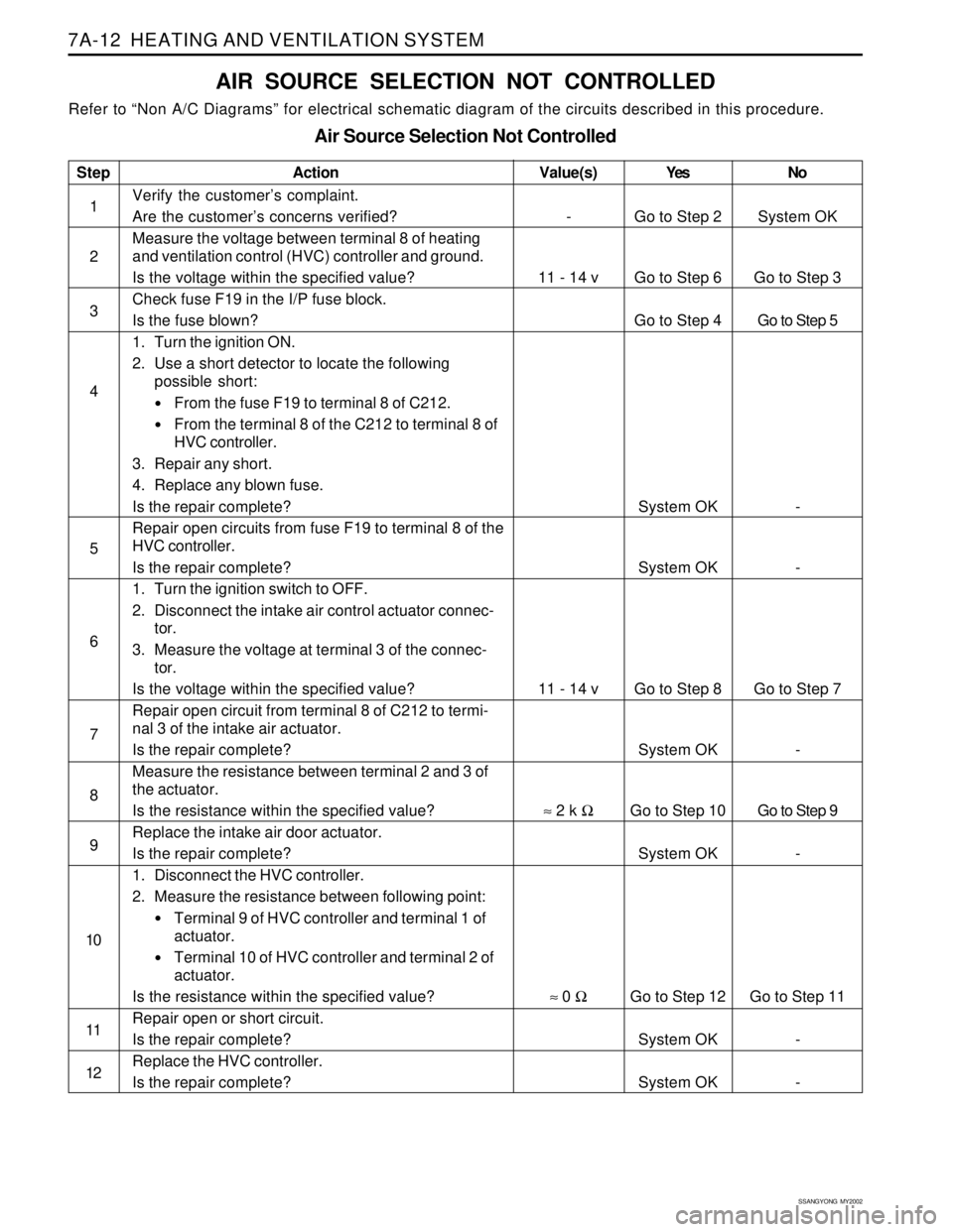
AIR SOURCE SELECTION NOT CONTROLLED
Refer to “Non A/C Diagrams” for electrical schematic diagram of the circuits described in this procedure.
Air Source Selection Not Controlled
Step
1
2
3
4
5
6
7
8
9
10
11
12Action
Verify the customer’s complaint.
Are the customer’s concerns verified?
Measure the voltage between terminal 8 of heating
and ventilation control (HVC) controller and ground.
Is the voltage within the specified value?
Check fuse F19 in the I/P fuse block.
Is the fuse blown?
1. Turn the ignition ON.
2. Use a short detector to locate the following
possible short:
From the fuse F19 to terminal 8 of C212.
From the terminal 8 of the C212 to terminal 8 of
HVC controller.
3. Repair any short.
4. Replace any blown fuse.
Is the repair complete?
Repair open circuits from fuse F19 to terminal 8 of the
HVC controller.
Is the repair complete?
1. Turn the ignition switch to OFF.
2. Disconnect the intake air control actuator connec-
tor.
3. Measure the voltage at terminal 3 of the connec-
tor.
Is the voltage within the specified value?
Repair open circuit from terminal 8 of C212 to termi-
nal 3 of the intake air actuator.
Is the repair complete?
Measure the resistance between terminal 2 and 3 of
the actuator.
Is the resistance within the specified value?
Replace the intake air door actuator.
Is the repair complete?
1. Disconnect the HVC controller.
2. Measure the resistance between following point:
Terminal 9 of HVC controller and terminal 1 of
actuator.
Terminal 10 of HVC controller and terminal 2 of
actuator.
Is the resistance within the specified value?
Repair open or short circuit.
Is the repair complete?
Replace the HVC controller.
Is the repair complete?Yes
Go to Step 2
Go to Step 6
Go to Step 4
System OK
System OK
Go to Step 8
System OK
Go to Step 10
System OK
Go to Step 12
System OK
System OKNo
System OK
Go to Step 3
Go to Step 5
-
-
Go to Step 7
-
Go to Step 9
-
Go to Step 11
-
-
Value(s)
-
11 - 14 v
11 - 14 v
≈ 2 k Ω
≈ 0 Ω