1997 SSANGYONG KORANDO relay
[x] Cancel search: relayPage 1672 of 2053
BODY WIRING SYSTEM 9A-21
SSANGYONG MY2002
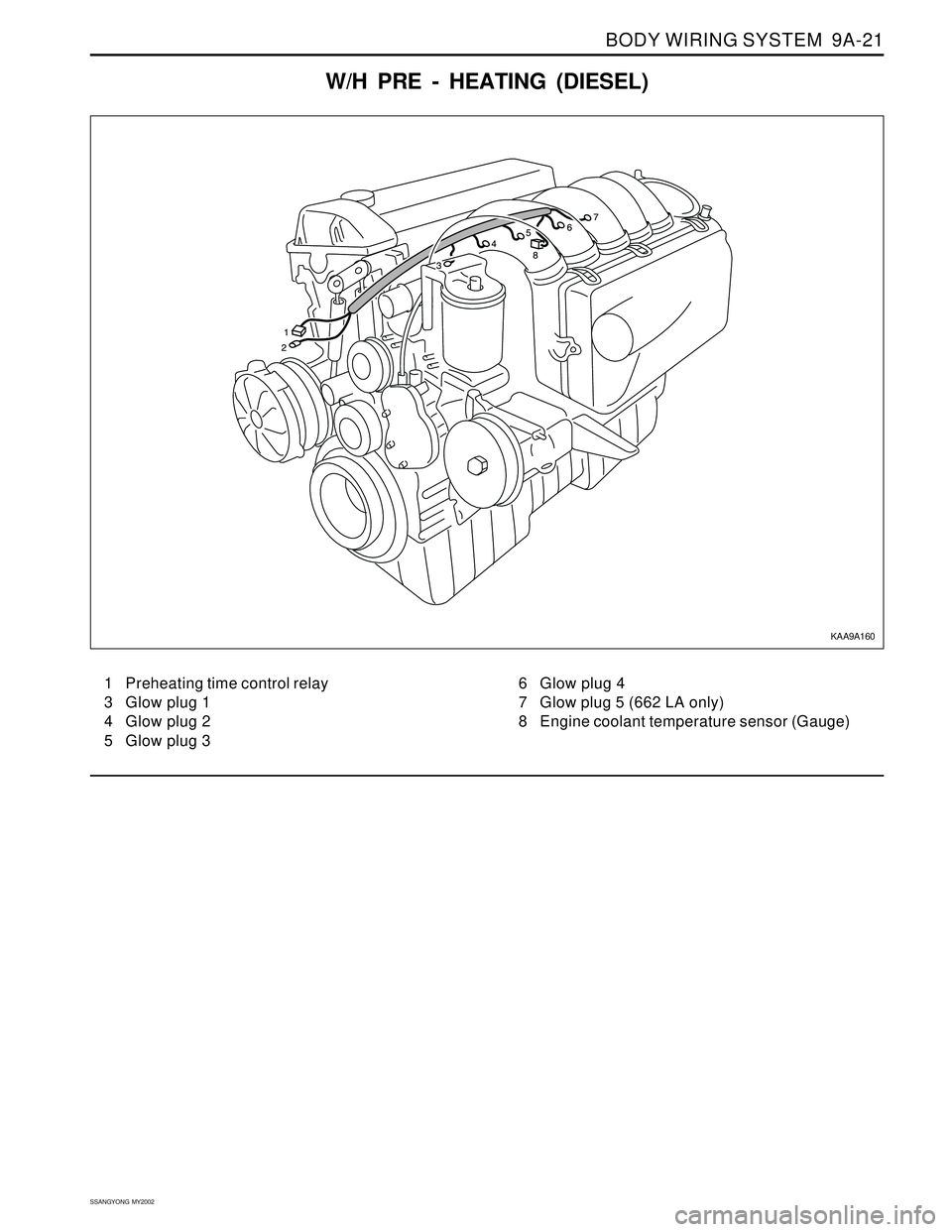
W/H PRE - HEATING (DIESEL)
1 Preheating time control relay
3 Glow plug 1
4 Glow plug 2
5 Glow plug 36 Glow plug 4
7 Glow plug 5 (662 LA only)
8 Engine coolant temperature sensor (Gauge)
KAA9A160
Page 1675 of 2053
SECTION 9B
LIGHTING SYSTEM
CAUTION: Disconnect the negative battery cable before removing or installing any electrical unit or when a
tool or equipment could easily come in contact with exposed electrical terminals. Disconnecting this cable
will help prevent personal injury and damage to the vehicle. The ignition must also be in LOCK unless
otherwise noted.
TABLE OF CONTENTS
Description and Operation...................................9B-2
Head Lamps - ON Reminder................................9B-2
Head Lamps........................................................9B-2
Daytime Running Lamps......................................9B-2
Parking and Turn Signal Lamps...........................9B-2
Fog Lamps..........................................................9B-2
Rear Combination Lamps.....................................9B-2
Center High-Mounted Stop Lamp.........................9B-2
Backup Lamps....................................................9B-3
License Plate Lamps ...........................................9B-3
Interior Room Lamps ...........................................9B-3
Luggage Lamps..................................................9B-3
Components Locator............................................9B-4
Diagnostic Information and Procedure...............9B-5
Head Lamps........................................................9B-5
Fog Lamps..........................................................9B-7
Tail Lamps..........................................................9B-8
Interior Room and Luggage Lamps....................9B-11
Door Courtesy Lamps ........................................9B-13
Cigar Lighter......................................................9B-14
Repair Instructions..............................................9B-15
On-Vehicle Service Unit Repair..............................9B-15
Head Lamps......................................................9B-15Front Combination Lamp....................................9B-16
Center High-Mounted Stop Lamp.......................9B-16
Rear Combination Lamps...................................9B-17
Fog Lamps........................................................9B-17
Interior Courtesy Lamp .......................................9B-18
Door Courtesy Lamp ..........................................9B-18
Luggage Lamp..................................................9B-19
License Plate Lamps .........................................9B-19
Specifications.....................................................9B-20
Bulb Usage Chart..............................................9B-20
Fastener Tightening Specifications.....................9B-20
Schematic and Routing Diagrams.....................9B-21
Head Lamp Leveling Device (HLLD) : Gasoline ..9B-21
Head Lamp Leveling Device (HLLD) : Diesel......9B-22
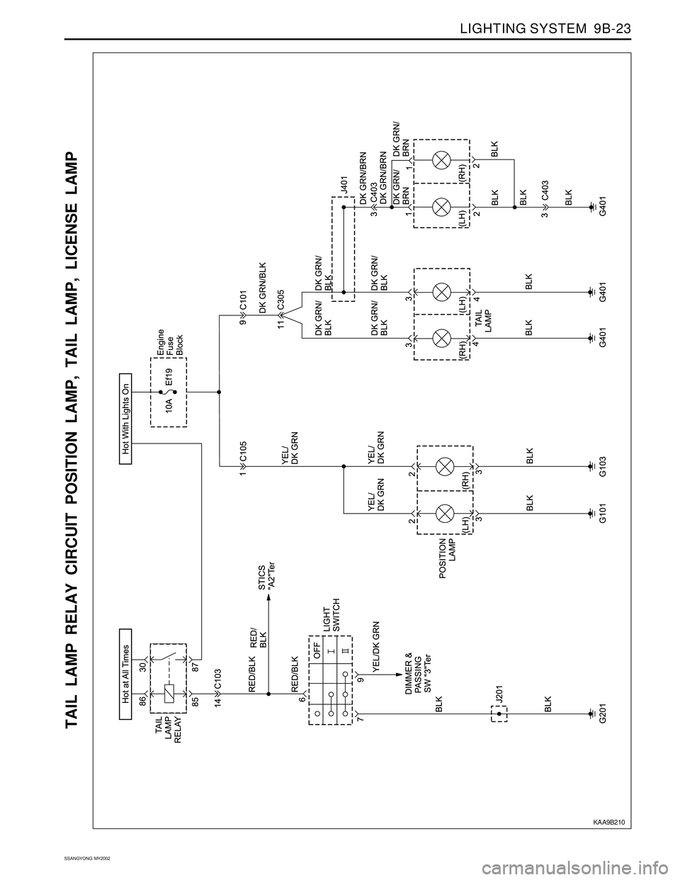
Tail Lamp Relay Circuit Position Lamp,
Tail Lamp, License Lamp................................9B-23
Illumination Switch.............................................9B-24
Turn Signal Lamp...............................................9B-25
Front Fog Lamp.................................................9B-26
Rear Fog Lamp..................................................9B-27
Stop Lamp, BTSI (Brake Transmission
Shift Interlock) - Metal Top..............................9B-28
Stop Lamp, BTSI (Brake Transmission
Shift Interlock) - Soft Top.................................9B-29
Page 1679 of 2053
LIGHTING SYSTEM 9B-5
SSANGYONG MY2002
DIAGNOSTIC INFORMATION AND PROCEDURE
HEAD LAMPS
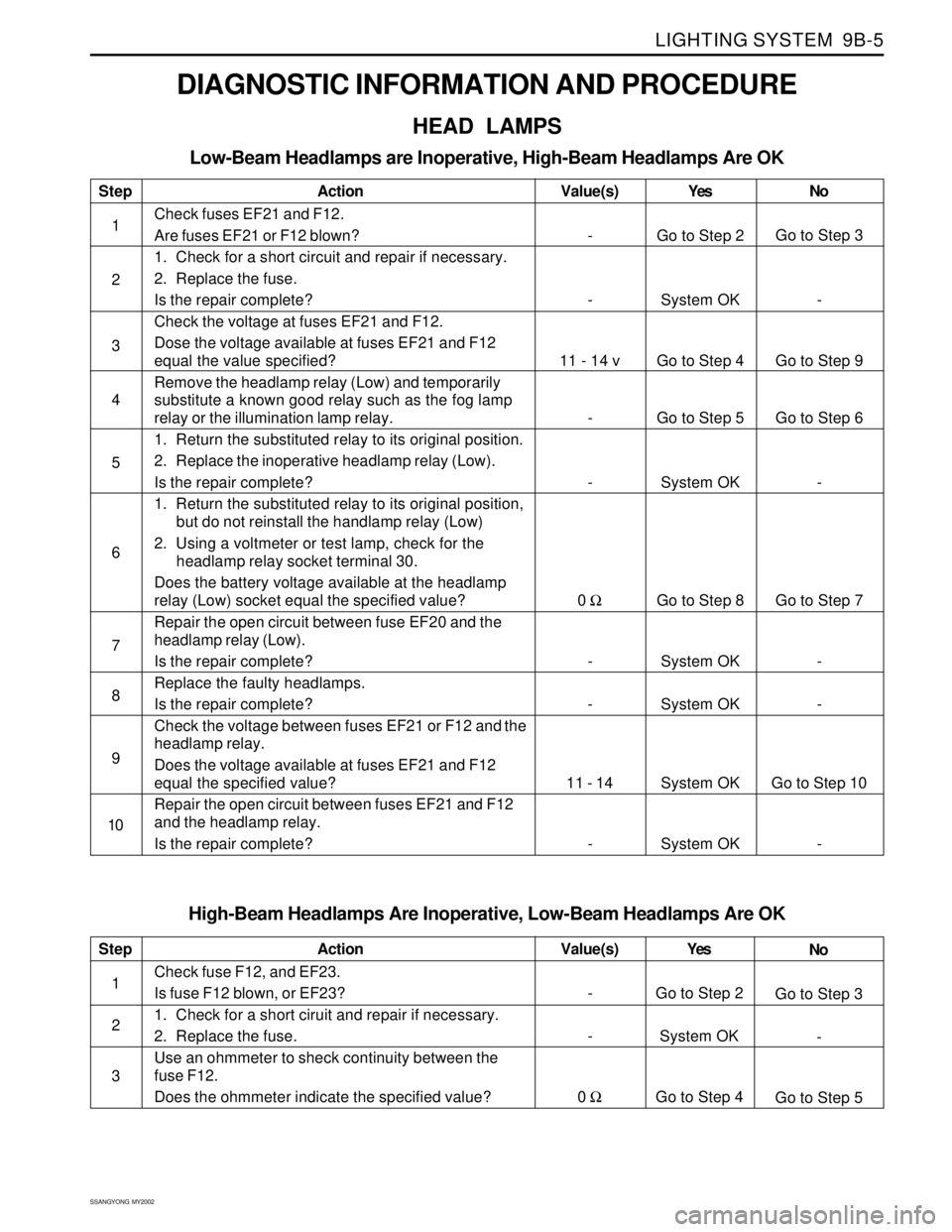
Low-Beam Headlamps are Inoperative, High-Beam Headlamps Are OK
Step
1
2
3
4
5
6
7
8
9
10Action
Check fuses EF21 and F12.
Are fuses EF21 or F12 blown?
1. Check for a short circuit and repair if necessary.
2. Replace the fuse.
Is the repair complete?
Check the voltage at fuses EF21 and F12.
Dose the voltage available at fuses EF21 and F12
equal the value specified?
Remove the headlamp relay (Low) and temporarily
substitute a known good relay such as the fog lamp
relay or the illumination lamp relay.
1. Return the substituted relay to its original position.
2. Replace the inoperative headlamp relay (Low).
Is the repair complete?
1. Return the substituted relay to its original position,
but do not reinstall the handlamp relay (Low)
2. Using a voltmeter or test lamp, check for the
headlamp relay socket terminal 30.
Does the battery voltage available at the headlamp
relay (Low) socket equal the specified value?
Repair the open circuit between fuse EF20 and the
headlamp relay (Low).
Is the repair complete?
Replace the faulty headlamps.
Is the repair complete?
Check the voltage between fuses EF21 or F12 and the
headlamp relay.
Does the voltage available at fuses EF21 and F12
equal the specified value?
Repair the open circuit between fuses EF21 and F12
and the headlamp relay.
Is the repair complete?Yes
Go to Step 2
System OK
Go to Step 4
Go to Step 5
System OK
Go to Step 8
System OK
System OK
System OK
System OKNo
Go to Step 3
-
Go to Step 9
Go to Step 6
-
Go to Step 7
-
-
Go to Step 10
- Value(s)
-
-
11 - 14 v
-
-
0 Ω
-
-
11 - 14
-
High-Beam Headlamps Are Inoperative, Low-Beam Headlamps Are OK
Step
1
2
3Action
Check fuse F12, and EF23.
Is fuse F12 blown, or EF23?
1. Check for a short ciruit and repair if necessary.
2. Replace the fuse.
Use an ohmmeter to sheck continuity between the
fuse F12.
Does the ohmmeter indicate the specified value?Yes
Go to Step 2
System OK
Go to Step 4No
Go to Step 3
-
Go to Step 5 Value(s)
-
-
0 Ω
Page 1681 of 2053
LIGHTING SYSTEM 9B-7
SSANGYONG MY2002
Step
1
2
3
4
5
6
7
8
9
10
11
12
13
14
15Action
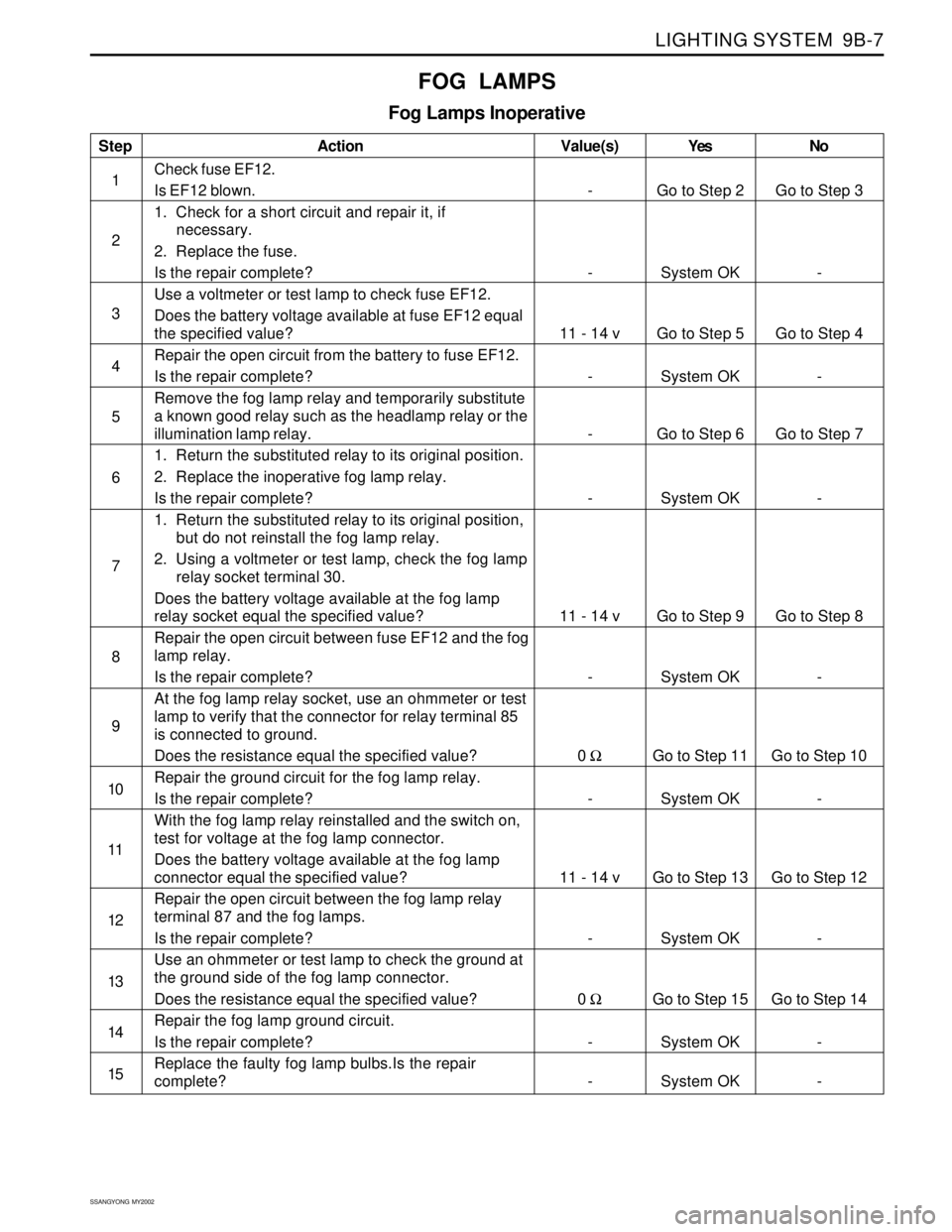
Check fuse EF12.
Is EF12 blown.
1. Check for a short circuit and repair it, if
necessary.
2. Replace the fuse.
Is the repair complete?
Use a voltmeter or test lamp to check fuse EF12.
Does the battery voltage available at fuse EF12 equal
the specified value?
Repair the open circuit from the battery to fuse EF12.
Is the repair complete?
Remove the fog lamp relay and temporarily substitute
a known good relay such as the headlamp relay or the
illumination lamp relay.
1. Return the substituted relay to its original position.
2. Replace the inoperative fog lamp relay.
Is the repair complete?
1. Return the substituted relay to its original position,
but do not reinstall the fog lamp relay.
2. Using a voltmeter or test lamp, check the fog lamp
relay socket terminal 30.
Does the battery voltage available at the fog lamp
relay socket equal the specified value?
Repair the open circuit between fuse EF12 and the fog
lamp relay.
Is the repair complete?
At the fog lamp relay socket, use an ohmmeter or test
lamp to verify that the connector for relay terminal 85
is connected to ground.
Does the resistance equal the specified value?
Repair the ground circuit for the fog lamp relay.
Is the repair complete?
With the fog lamp relay reinstalled and the switch on,
test for voltage at the fog lamp connector.
Does the battery voltage available at the fog lamp
connector equal the specified value?
Repair the open circuit between the fog lamp relay
terminal 87 and the fog lamps.
Is the repair complete?
Use an ohmmeter or test lamp to check the ground at
the ground side of the fog lamp connector.
Does the resistance equal the specified value?
Repair the fog lamp ground circuit.
Is the repair complete?
Replace the faulty fog lamp bulbs.Is the repair
complete?Yes
Go to Step 2
System OK
Go to Step 5
System OK
Go to Step 6
System OK
Go to Step 9
System OK
Go to Step 11
System OK
Go to Step 13
System OK
Go to Step 15
System OK
System OKNo
Go to Step 3
-
Go to Step 4
-
Go to Step 7
-
Go to Step 8
-
Go to Step 10
-
Go to Step 12
-
Go to Step 14
-
- Value(s)
-
-
11 - 14 v
-
-
-
11 - 14 v
-
0 Ω
-
11 - 14 v
-
0 Ω
-
-
FOG LAMPS
Fog Lamps Inoperative
Page 1697 of 2053
LIGHTING SYSTEM 9B-23
SSANGYONG MY2002
TAIL LAMP RELAY CIRCUIT POSITION LAMP, TAIL LAMP, LICENSE LAMP
KAA9B210
Page 1851 of 2053
SSANGYONG MY2002
9T1-4 REMOTE KEYLESS ENTRY AND ANTI-THEFT SYSTEM
DIAGNOSTIC INFORMATION AND PROCEDURE
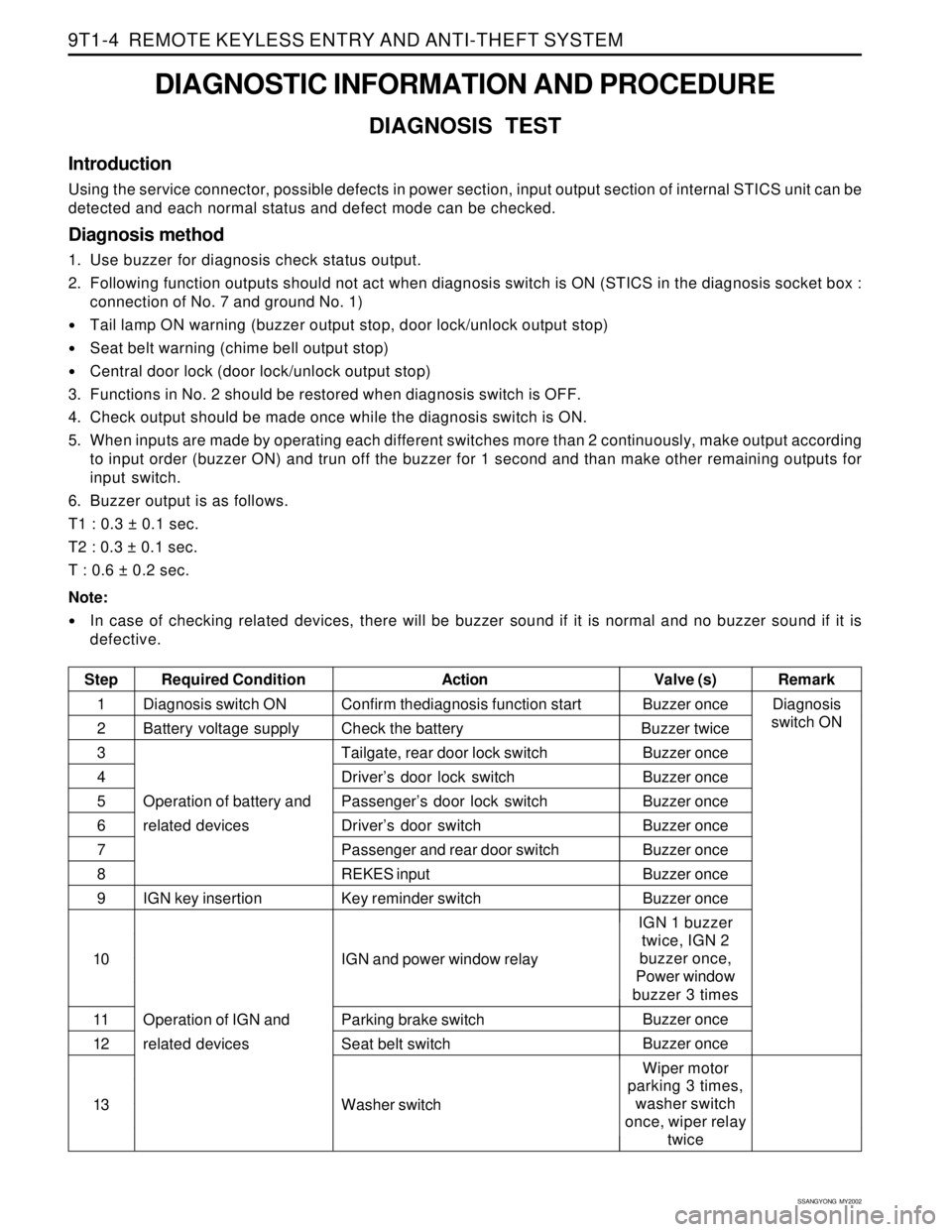
DIAGNOSIS TEST
Introduction
Using the service connector, possible defects in power section, input output section of internal STICS unit can be
detected and each normal status and defect mode can be checked.
Diagnosis method
1. Use buzzer for diagnosis check status output.
2. Following function outputs should not act when diagnosis switch is ON (STICS in the diagnosis socket box :
connection of No. 7 and ground No. 1)
Tail lamp ON warning (buzzer output stop, door lock/unlock output stop)
Seat belt warning (chime bell output stop)
Central door lock (door lock/unlock output stop)
3. Functions in No. 2 should be restored when diagnosis switch is OFF.
4. Check output should be made once while the diagnosis switch is ON.
5. When inputs are made by operating each different switches more than 2 continuously, make output according
to input order (buzzer ON) and trun off the buzzer for 1 second and than make other remaining outputs for
input switch.
6. Buzzer output is as follows.
T1 : 0.3 ± 0.1 sec.
T2 : 0.3 ± 0.1 sec.
T : 0.6 ± 0.2 sec.
Note:
In case of checking related devices, there will be buzzer sound if it is normal and no buzzer sound if it is
defective.
Step Required ConditionActionRemark Valve (s)
Diagnosis switch ON
Battery voltage supply
Operation of battery and
related devices
IGN key insertion
Operation of IGN and
related devicesBuzzer once
Buzzer twice
Buzzer once
Buzzer once
Buzzer once
Buzzer once
Buzzer once
Buzzer once
Buzzer once
IGN 1 buzzer
twice, IGN 2
buzzer once,
Power window
buzzer 3 times
Buzzer once
Buzzer once
Wiper motor
parking 3 times,
washer switch
once, wiper relay
twice Confirm thediagnosis function start
Check the battery
Tailgate, rear door lock switch
Driver’s door lock switch
Passenger’s door lock switch
Driver’s door switch
Passenger and rear door switch
REKES input
Key reminder switch
IGN and power window relay
Parking brake switch
Seat belt switch
Washer switch1
2
3
4
5
6
7
8
9
10
11
12
13Diagnosis
switch ON
Page 1852 of 2053

REMOTE KEYLESS ENTRY AND ANTI-THEFT SYSTEM 9T1-5
SSANGYONG MY2002
KAA9T020
KAA9T030
INPUT MEMORY
When the REKES transmitter is lost
1. Connect the battery terminal No. 3 and REKES
terminal No. 4 which are on the diagnosis socket
under the dash board with service lead wire.
2. push the lock or unlock button on the REKES
transmitter.
3. Input memory and close all doors.
4. Check the operation of door locking system by
pushing the lock or unlock button on the REKES
transmitter.
When the transmitter is faulty
1. Connect the battery terminal No. 3 and REKES
terminal No. 4 which are on the diagnosis socket
under the dash board with service lead wire.
2. Set the input switch of the REKES receiver onto
the No. 1 or No. 2 position and push the lock or
unlock button on the REKES transmitter.
3. Set the input switch of the REKES receiver onto
the central position and close all doors.
4. Check the operation of door locking system by
pushing the lock or unlock button on the REKES
transmitter.
Step Required ConditionActionRemark Valve (s)
Wiper motor
parking 3 times,
washer switch
once, wiper relay
twice
Buzzer once
Buzzer once
Buzzer once
Buzzer once Wiper auto switch
ALT ‘L’
Volume variable switch
Defogger switch
Speed sensor signal
Operation of IGN and
related devices
Operation of IGN and
starting and related
devices14
15
16
17
18
KAA9T100
Page 1863 of 2053
1-2 1-2 1-2 1-2
1-2
HOW TO USE ELECTRICAL WIRING DIAGRAM HOW TO USE ELECTRICAL WIRING DIAGRAMHOW TO USE ELECTRICAL WIRING DIAGRAM HOW TO USE ELECTRICAL WIRING DIAGRAM
HOW TO USE ELECTRICAL WIRING DIAGRAM1. 1.1. 1.
1.
HO HOHO HO
HO
W W W W
W
T TT T
T
O READ ELECTRICAL O READ ELECTRICAL O READ ELECTRICAL O READ ELECTRICAL
O READ ELECTRICAL
WIRING DIA WIRING DIAWIRING DIA WIRING DIA
WIRING DIA
GRAM GRAMGRAM GRAM
GRAM
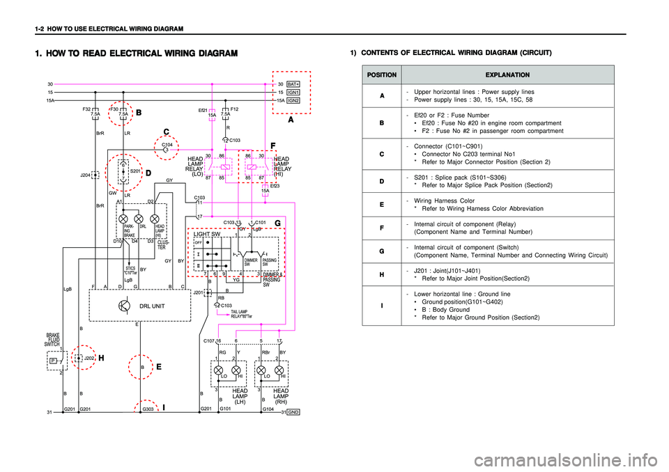
1) 1)1) 1)
1)
CONTENTS OF ELECTRICAL WIRING DIAGRAM (CIRCUIT) CONTENTS OF ELECTRICAL WIRING DIAGRAM (CIRCUIT)CONTENTS OF ELECTRICAL WIRING DIAGRAM (CIRCUIT) CONTENTS OF ELECTRICAL WIRING DIAGRAM (CIRCUIT)
CONTENTS OF ELECTRICAL WIRING DIAGRAM (CIRCUIT)
POSITION POSITIONPOSITION POSITION
POSITION
EXPLANATION EXPLANATIONEXPLANATION EXPLANATION
EXPLANATION
- Upper horizontal lines : Power supply lines
- Power supply lines : 30, 15, 15A, 15C, 58
- Ef20 or F2 : Fuse Number
• Ef20 : Fuse No #20 in engine room compartment
F2 : Fuse No #2 in passenger room compartment
- Connector (C101~C901)
Connector No C203 terminal No1
* Refer to Major Connector Position (Section 2)
- S201 : Splice pack (S101~S306)
* Refer to Major Splice Pack Position (Section2)
- Wiring Harness Color
* Refer to Wiring Harness Color Abbreviation
- Internal circuit of component (Relay)
(Component Name and Terminal Number)
- Internal circuit of component (Switch)
(Component Name, Terminal Number and Connecting Wiring Circuit)
- J201 : Joint(J101~J401)
* Refer to Major Joint Position(Section2)
- Lower horizontal line : Ground line
Ground position(G101~G402)
B : Body Ground
* Refer to Major Ground Position (Section2) A AA A
A
B BB B
B
C CC C
C
D DD D
D
E EE E
E
F FF F
F
G GG G
G
H HH H
H
I II I
I
A AA A
A B BB B
B
C CC C
C
D DD D
DF FF F
F
G GG G
G
E EE E
E
I II I
I H HH H
H