1997 SSANGYONG KORANDO relay
[x] Cancel search: relayPage 567 of 2053

1B3 -- 18 OM600 ENGINE MECHANICAL
D AEW OO M Y_2000
27. Disconnect the preheating time relay sensor plug.
28. Disconnect the coolant temperature sensor plug.
29. Disconnect the accelerator cable from the control
linkage.
Installation Notice
Tightening Torque8--18 N∙m (6 -- 13 lb-ft)
30. Loosen the connection of control pressure cable (an
arrow) used in auto transmisson.
Page 985 of 2053

SECTION 4F
ANTILOCK BRAKE SYSTEM AND
TRACTION CONTROL SYSTEM
TABLE OF CONTENTS
General Description and System Opertion..........4F-3
Basic Knowledge Required...................................4F-3
ABS System Components...................................4F-3
Traction Control System (TCS) Description...........4F-3
EBD System........................................................4F-5
EBD Failure Matrix...............................................4F-6
Tires and ABS/TCS..............................................4F-7
Hydraulic Circuit...................................................4F-8
ABS 5.3...............................................................4F-8
ABS/TCS 5.3.....................................................4F-11
Component Locator...........................................4F-14
ABS, ABS/TCS 5.3............................................4F-14
Diagnosis............................................................4F-15
Diagnostic Circuit Check....................................4F-15
ABS Indicator Lamp Inoperative.........................4F-18
Traction Control System (TCS) Indicator Lamp
Inoperative.....................................................4F-22
EBD Indicator Lamp Inoperative.........................4F-26
Power Supply to Control Module,
No DTCs Stored..............................................4F-30
ABS Indicator Lamp Illuminated Continuously,
No DTCs Stored..............................................4F-34
Self-Diagnostics................................................4F-36
Displaying DTCs................................................4F-36
Clearing DTCs...................................................4F-36
Intermittents and Poor Connections....................4F-36
DTC 03 - Left Front Wheel Speed Sensor Fault ...4F-38
DTC 07 - Left Front Wheel Speed Sensor
Continuity Fault...............................................4F-40
DTC 04 - Right Front Wheel Speed Sensor
Fault...............................................................4F-42DTC 08 - Right Front Wheel Speed Sensor
Continuity Fault...............................................4F-44
DTC 05 - Left Rear Wheel Speed Sensor Fault....4F-46
DTC 09 - Left Rear Wheel Speed Sensor
Continuity Fault...............................................4F-48
DTC 06 - Right Rear Wheel Speed Sensor Fault .4F-50
DTC 10 - Right Rear Wheel Speed Sensor
Continuity Fault...............................................4F-52
DTC 11 - Wheel Speed Sensor Frequency Error ..4F-54
DTC 42 - Acceleration Sensor Fault....................4F-58
DTC 43 - Acceleration Sensor Continuity Fault.....4F-60
DTC 13/14 - Left Front Inlet and Outlet Valve
Solenoid Fault.................................................4F-62
DTC 15/16 - Right Front Inlet and Outlet Valve
Solenoid Fault.................................................4F-64
DTC 17/18 - Left Rear Inlet and Outlet Valve
Solenoid Fault.................................................4F-66
DTC 19/20 - Right Rear Inlet and Outlet Valve
Solenoid Fault.................................................4F-68
DTC 21/22 - Left Rear Prime Line and Traction
Control System (TCS) Pilot Valve Fault............4F-70
DTC 23/24 - Right Rear Prime Line and Traction
Control System (TCS) Pilot Valve Fault............4F-72
DTC 12 - Valve Relay Circuit Fault......................4F-74
DTC 24 - Pump Motor or Pump Motor
Relay Fault.....................................................4E-76
DTC 27 - Stoplamp Switch Fault.........................4E-80
DTC 28 - Low Voltage Fault................................4E-84
DTC 02 - ABS Control Module Internal Fault........4E-88
Scheatic and Routing Diagrams........................4E-90
ABS Circuit (Without TCS): Gasoline...................4E-90
ABS/TCS Circuit: Gasoline.................................4E-91
ABS/ABD (Automatic Brake
Differential Lock): Diesel.................................4E-93
Page 1019 of 2053
SSANGYONG MY2002
4F-36 ABS AND TCS
SELF-DIAGNOSTICS
Important: The electronic brake control module (EBCM)
turns the valve relay off when a diagnostic trouble code
(DTC) is set. The scan tool will indicate that the valve
relay is off when it is used to monitor the data list. This
is normal and should not be considered a mal-function.
The EBCM performs system self-diagnostics and can
detect and often isolate system malfunctions. When it
detects a malfunction, the EBCM sets a DTC that repre
sents the malfunction, turns on the ABS and/or the
TCS indicators in most instances, and may disable the
ABS and/or the TCS functions, as necessary, for the
duration of the ignition cycle.
Once each ignition cycle, the EBCM performs an auto-
matic test when the vehicle reaches 2.75 km/h (1.7
mph). In the course of this test, the system cycles
each valve solenoid and the pump motor, along with
the necessary relays, to check component operation.
If the EBCM detects any malfunctions, it will set a
DTC as described above.
DISPLAYING DTCs
Tools Required
Scan Tool
DTCs can be read through the use of the scan tool.
CLEARING DTCs
Tools Required
Scan Tool
The diagnostic trouble codes (DTCs) in the electronic
brake control module (EBCM) memory are erased in
one of two ways:
Use the scan tool “Clear DTCs” selection.
After 249 DTC-free ignition cycles.
These two methods are detailed below. Be sure to verify
the proper system operation and, the absence of DTCs
when the clearing procedure is completed.The EBCM will not permit DTC clearing until all DTCs
have been displayed. Also, DTCs cannot be cleared
by disconnecting the EBCM, disconnecting the battery
cables, or turning the ignition switch to LOCK.
Scan Tool Method
The scan tool can clear ABS/TCS system DTCs using
the mass storage cartridge.
1. Install the scan tool and the mass storage
cartridge.
2. Select “Fault Memory”.
3. Select “Clear Fault Memory”.
Clearing the fault memory cannot reset a valve relay
which was shut down when the fault was recognized.
Changes are possible only after the fault has been elimi-
nated and the next ignition cycle has begun.
Ignition Cycle Default
A DTC is erased from memory after 249 ignition cycles
without any reappearance of that malfunction.
INTERMITTENTS AND POOR
CONNECTIONS
As with most electronic systems, intermittent malfunc
tions may be difficult to diagnose accurately. The follow-
ing is a method to try to isolate an intermittent
malfunction, especially in wheel speed circuitry.
If an ABS malfunction occurs, the ABS indicator will
illuminate during the ignition cycle in which the
malfunction was detected. If it is an intermittent problem
which seems to have corrected itself (ABS indicator
OFF), a history DTC will be stored. Also stored will be
the history data of the DTC at the time the malfunction
occurred. Use the scan tool modular diagnostic system
to read ABS history data.
Most intermittents are caused by faulty electrical con
nections or wiring, although a sticking relay or solenoid
can occasionally be at fault.
Page 1045 of 2053
SSANGYONG MY2002
4F-62 ABS AND TCS
DIAGNOSTIC TROUBLE CODE (DTC) 13/14
LEFT FRONT INLET AND OUTLET VALVE SOLENOID FAULT
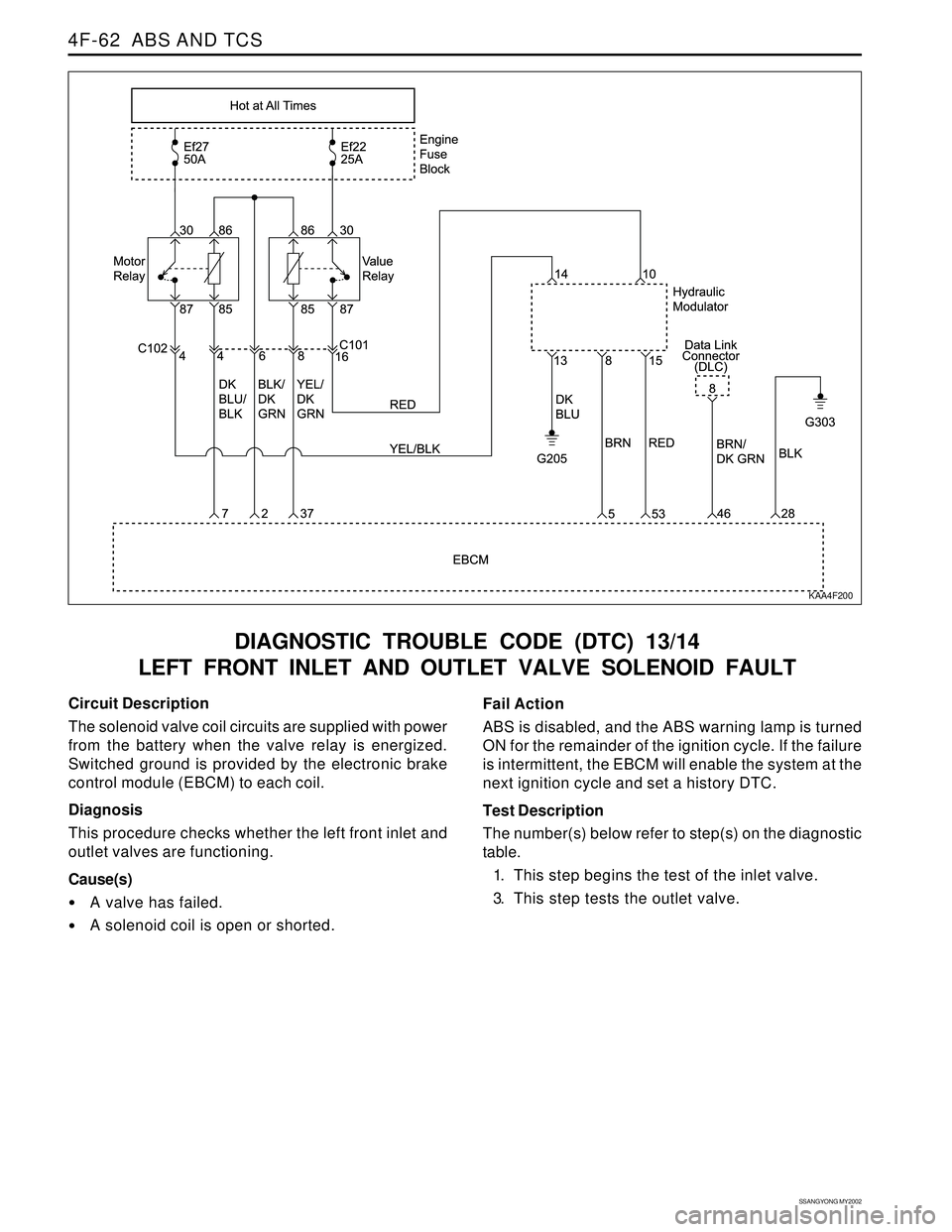
KAA4F200
Circuit Description
The solenoid valve coil circuits are supplied with power
from the battery when the valve relay is energized.
Switched ground is provided by the electronic brake
control module (EBCM) to each coil.
Diagnosis
This procedure checks whether the left front inlet and
outlet valves are functioning.
Cause(s)
A valve has failed.
A solenoid coil is open or shorted.Fail Action
ABS is disabled, and the ABS warning lamp is turned
ON for the remainder of the ignition cycle. If the failure
is intermittent, the EBCM will enable the system at the
next ignition cycle and set a history DTC.
Test Description
The number(s) below refer to step(s) on the diagnostic
table.
1. This step begins the test of the inlet valve.
3. This step tests the outlet valve.
Page 1047 of 2053
SSANGYONG MY2002
4F-64 ABS AND TCS
DIAGNOSTIC TROUBLE CODE (DTC) 15/16
RIGHT FRONT INLET AND OUTLET VALVE SOLENOID FAULT
KAA4F200
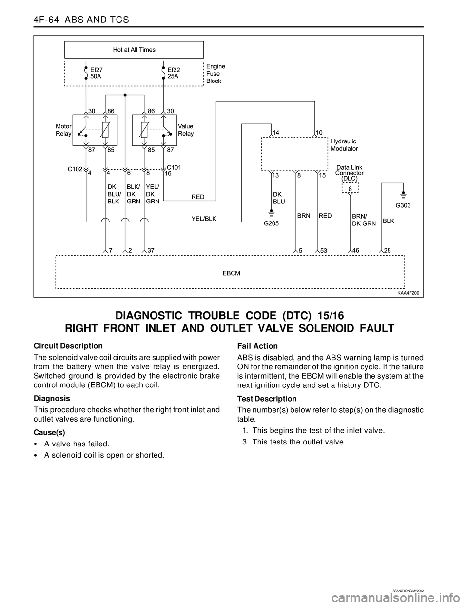
Circuit Description
The solenoid valve coil circuits are supplied with power
from the battery when the valve relay is energized.
Switched ground is provided by the electronic brake
control module (EBCM) to each coil.
Diagnosis
This procedure checks whether the right front inlet and
outlet valves are functioning.
Cause(s)
A valve has failed.
A solenoid coil is open or shorted.Fail Action
ABS is disabled, and the ABS warning lamp is turned
ON for the remainder of the ignition cycle. If the failure
is intermittent, the EBCM will enable the system at the
next ignition cycle and set a history DTC.
Test Description
The number(s) below refer to step(s) on the diagnostic
table.
1. This begins the test of the inlet valve.
3. This tests the outlet valve.
Page 1049 of 2053
SSANGYONG MY2002
4F-66 ABS AND TCS
DIAGNOSTIC TROUBLE CODE (DTC) 17/18
LEFT REAR INLET AND OUTLET VALVE SOLENOID FAULT
KAA4F200
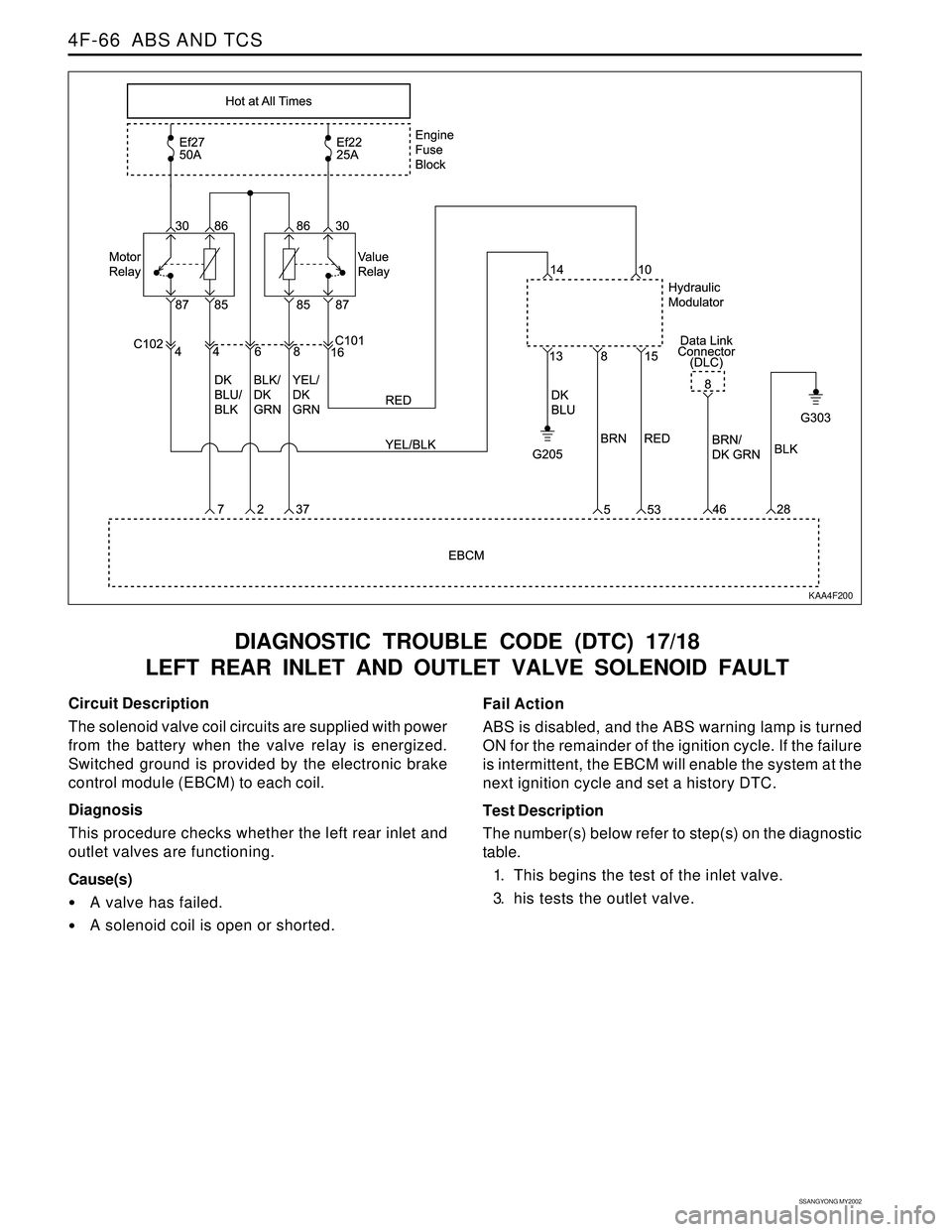
Circuit Description
The solenoid valve coil circuits are supplied with power
from the battery when the valve relay is energized.
Switched ground is provided by the electronic brake
control module (EBCM) to each coil.
Diagnosis
This procedure checks whether the left rear inlet and
outlet valves are functioning.
Cause(s)
A valve has failed.
A solenoid coil is open or shorted.Fail Action
ABS is disabled, and the ABS warning lamp is turned
ON for the remainder of the ignition cycle. If the failure
is intermittent, the EBCM will enable the system at the
next ignition cycle and set a history DTC.
Test Description
The number(s) below refer to step(s) on the diagnostic
table.
1. This begins the test of the inlet valve.
3. his tests the outlet valve.
Page 1051 of 2053
SSANGYONG MY2002
4F-68 ABS AND TCS
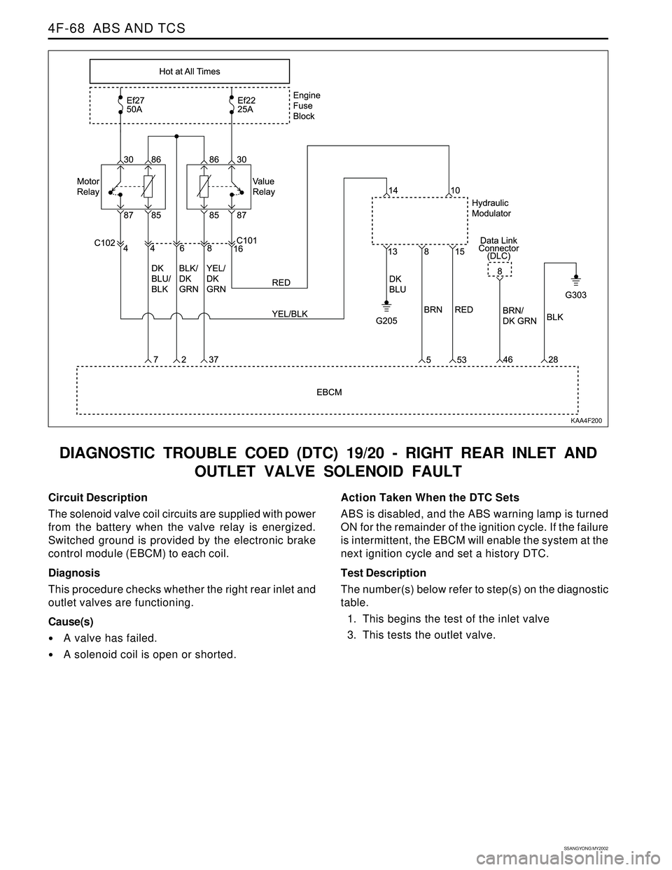
DIAGNOSTIC TROUBLE COED (DTC) 19/20 - RIGHT REAR INLET AND
OUTLET VALVE SOLENOID FAULT
Circuit Description
The solenoid valve coil circuits are supplied with power
from the battery when the valve relay is energized.
Switched ground is provided by the electronic brake
control module (EBCM) to each coil.
Diagnosis
This procedure checks whether the right rear inlet and
outlet valves are functioning.
Cause(s)
A valve has failed.
A solenoid coil is open or shorted.Action Taken When the DTC Sets
ABS is disabled, and the ABS warning lamp is turned
ON for the remainder of the ignition cycle. If the failure
is intermittent, the EBCM will enable the system at the
next ignition cycle and set a history DTC.
Test Description
The number(s) below refer to step(s) on the diagnostic
table.
1. This begins the test of the inlet valve
3. This tests the outlet valve.
KAA4F200
Page 1053 of 2053
SSANGYONG MY2002
4F-70 ABS AND TCS
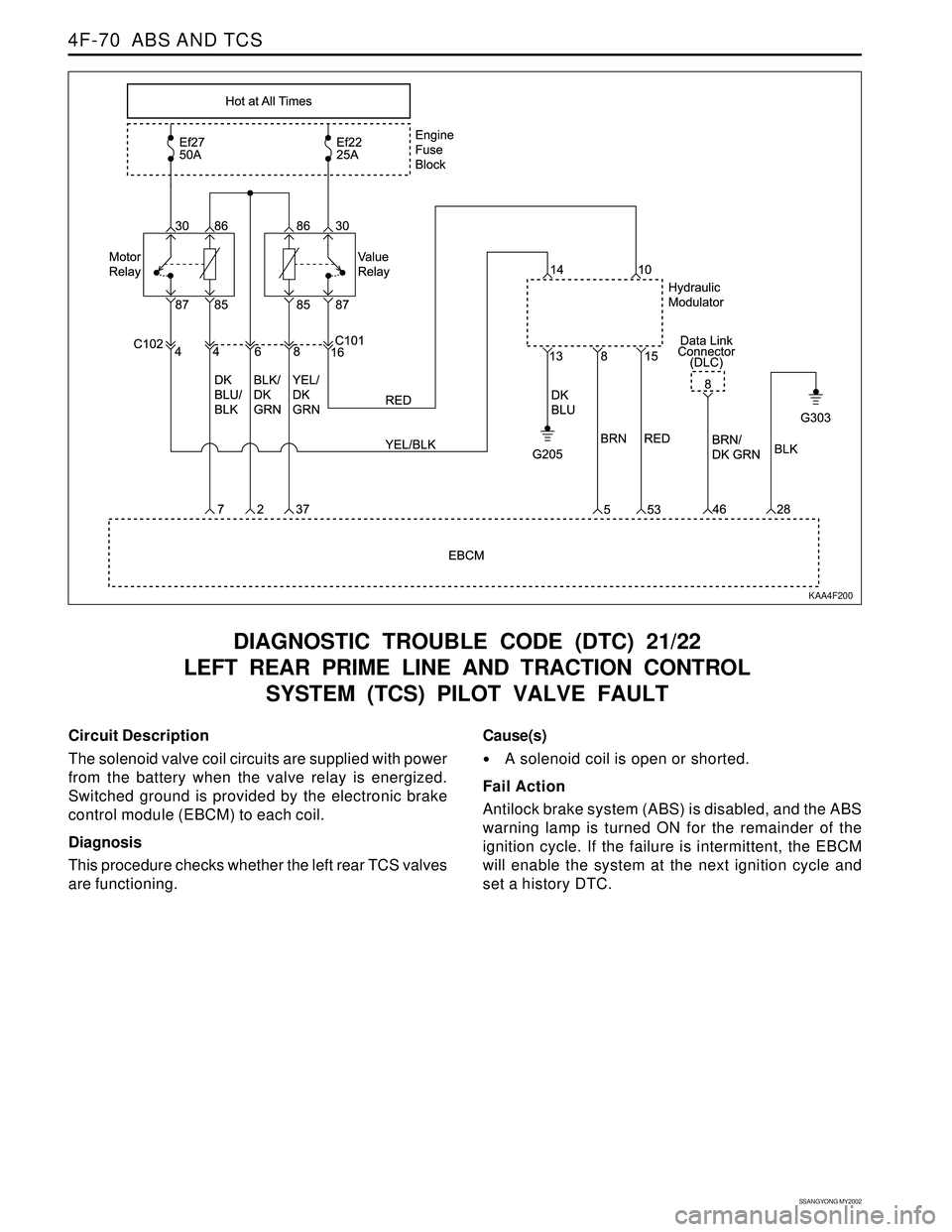
DIAGNOSTIC TROUBLE CODE (DTC) 21/22
LEFT REAR PRIME LINE AND TRACTION CONTROL
SYSTEM (TCS) PILOT VALVE FAULT
KAA4F200
Circuit Description
The solenoid valve coil circuits are supplied with power
from the battery when the valve relay is energized.
Switched ground is provided by the electronic brake
control module (EBCM) to each coil.
Diagnosis
This procedure checks whether the left rear TCS valves
are functioning.Cause(s)
A solenoid coil is open or shorted.
Fail Action
Antilock brake system (ABS) is disabled, and the ABS
warning lamp is turned ON for the remainder of the
ignition cycle. If the failure is intermittent, the EBCM
will enable the system at the next ignition cycle and
set a history DTC.