Page 537 of 2053
1A3 -- 2 GENERAL ENGINE INFORMATION
D AEW OO M Y_2000
ENGINE SPECIFICATIONS (Cont’d)
ApplicationOM662LAOM661LA
Idle Speed (rpm)720 -- 820750 -- 850
Fuel Injection Pressure (bar)135 -- 143135 -- 143
Oil Capacity (liter)8.0 -- 9.56.5 -- 8.0
Lubrication TypeForced by Gear PumpForced by Gear Pump
Oil Filter TypeCombined Full-- Flow and Partial
Flow FilterCombined Full-- Flow and Partial
Flow Filter
FuelDieselDiesel
Page 547 of 2053

1A3 -- 12 GENERAL ENGINE INFORMATION
D AEW OO M Y_2000
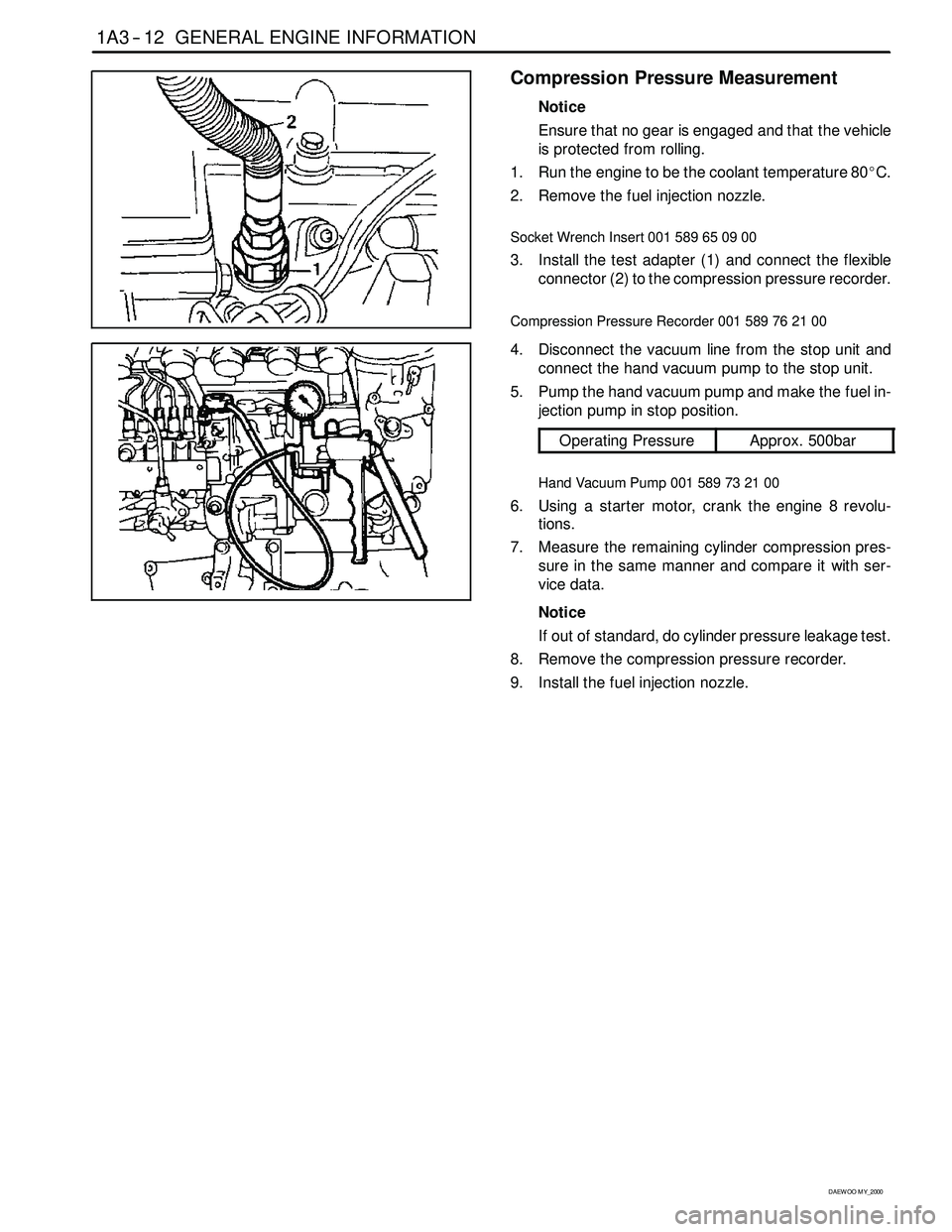
Compression Pressure Measurement
Notice
Ensure that no gear is engaged and that the vehicle
is protected from rolling.
1. Run the engine to be the coolant temperature 80_C.
2. Remove the fuel injection nozzle.
Socket Wrench Insert 001 589 65 09 00
3. Install the test adapter (1) and connect the flexible
connector (2) to the compression pressure recorder.
Compression Pressure Recorder 001 589 76 21 00
4. Disconnect the vacuum line from the stop unit and
connect the hand vacuum pump to the stop unit.
5. Pump the hand vacuum pump and make the fuel in-
jection pump in stop position.
Operating PressureApprox. 500bar
Hand Vacuum Pump 001 589 73 21 00
6. Using a starter motor, crank the engine 8 revolu-
tions.
7. Measure the remaining cylinder compression pres-
sure in the same manner and compare it with ser-
vice data.
Notice
If out of standard, do cylinder pressure leakage test.
8. Remove the compression pressure recorder.
9. Install the fuel injection nozzle.
Page 549 of 2053

1A3 -- 14 GENERAL ENGINE INFORMATION
D AEW OO M Y_2000
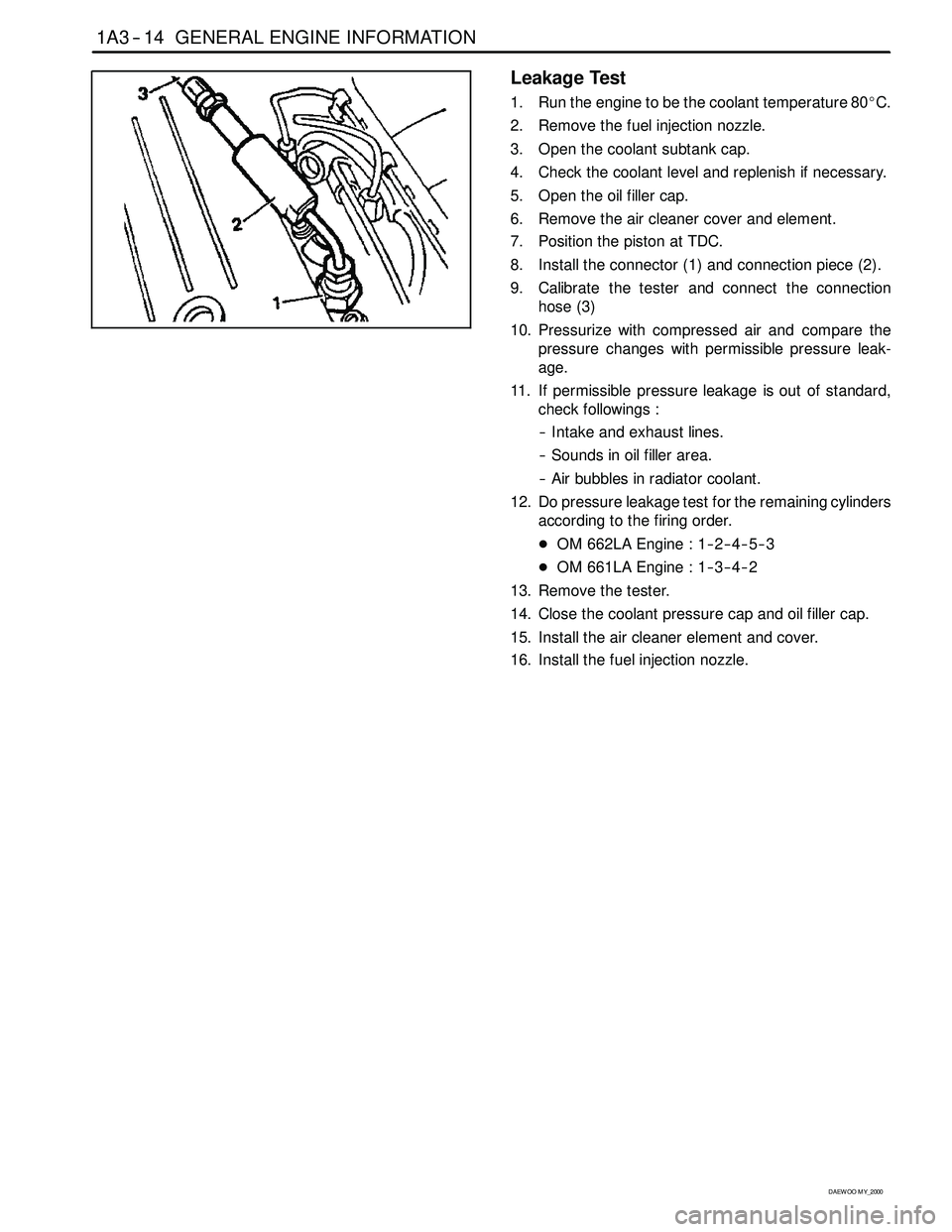
Leakage Test
1. Run the engine to be the coolant temperature 80_C.
2. Remove the fuel injection nozzle.
3. Open the coolant subtank cap.
4. Check the coolant level and replenish if necessary.
5. Open the oil filler cap.
6. Remove the air cleaner cover and element.
7. Position the piston at TDC.
8. Install the connector (1) and connection piece (2).
9. Calibrate the tester and connect the connection
hose (3)
10. Pressurize with compressed air and compare the
pressure changes with permissible pressure leak-
age.
11. If permissible pressure leakage is out of standard,
check followings :
-- Intake and exhaust lines.
-- Sounds in oil filler area.
-- Air bubbles in radiator coolant.
12. Do pressure leakage test for the remaining cylinders
according to the firing order.
DOM 662LA Engine : 1-- 2-- 4-- 5-- 3
DOM 661LA Engine : 1-- 3-- 4-- 2
13. Remove the tester.
14. Close the coolant pressure cap and oil filler cap.
15. Install the air cleaner element and cover.
16. Install the fuel injection nozzle.
Page 641 of 2053

1B3 -- 92 OM600 ENGINE MECHANICAL
D AEW OO M Y_2000
24. Insert the new connecting rod bearing shells into the
connecting rod and connecting rod bearing cap and
tighten the 12--sided stretch bolts (11).
Tightening Torque40 N∙m (30 lb-ft) + 90_
25. Measure inner diameter of connecting rod bearing.
26. Measure connecting rod bearing journal diameter
(K).
Notice
Refer to measurement of the crankshaft bearing
journal diameter.
27. Measure the radial clearance (L) of the connecting
rod bearing.
Example) Measured value ’J’ = 47.700mm
Measured value ’K’ = 47.653mm
——————————————
Clearance ’L’ = 0.047mm
Radial Clearance ’L’0.026 -- 0.068mm
Notice
If the clearance is out of standard, adjust the radial
clearance of connecting rod bearing by replacing the
connecting rod bearing shells.
28. Remove the connecting rod bearing cap.
29. Install the piston.
30. Rotate the crankshaft by hand and check whether it
rotates smoothly.
31. If the bearings are damaged,
-- replace the oil presser relief valve.
-- clean the oil pump and oil filter housing carefully
and replace the hose if necessary.
Notice
After assembling the engine, check the camshaft
timing, adjust the start of fuel injection and check the
TDC sensor bracket setting.
32. Fill oil and run the engine and then check the oil
pressure and oil level.
Notice
Install the original oil filter element and then change
the engine oil and oil filter element after 1,000 --
1,500km.
Page 763 of 2053

D AEW OO M Y_2000
SECTION 1F3
OM600 ENGINE CONTROLS
Caution: Disconnect the negative battery cable before removing or installing any electrical unit or when a
tool or equipment could easily come in contact with exposed electrical terminals. Disconnecting this cable
will help prevent personal injury and damage to the vehicle. The ignition must also be in LOCK unless other -
wise noted.
TABLE OF CONTENTS
Specifications 1F3 -- 1............................
Fastener Tightening Specifications 1F3 -- 1..........
Maintenance and Repair 1F3 -- 2...................
On -- Vehicle Service 1F3 -- 2.........................
Fuel System 1F3 -- 2.............................
Fuel Injection Pump Coding 1F3 -- 3................
Fuel Tank 1F3 -- 4...............................
Vacuum Control System Test 1F3 -- 5..............
Vacuum Pump Test 1F3 -- 10......................
Vacuum Pump 1F3 -- 12..........................
Vacuum Unit Replacement 1F3 -- 14...............
Idle Speed Adjustment 1F3 -- 15...................Fuel Pump Test 1F3 -- 17.........................
Fuel Pump 1F3 -- 20.............................
Injection Nozzle Test 1F3-- 21.....................
Injection Nozzles 1F3-- 24........................
Injection Nozzle Repair 1F3 -- 26...................
Removal and Installation of
Injection Timing Device 1F3 -- 29.................
Injection Timing Device 1F3 -- 34...................
StartofDeliveryTest
(Position Sensor, RIV Method) 1F3 -- 36..........
Fuel Injection Pump 1F3 -- 45.....................
SPECIFICATIONS
FASTENER TIGHTENING SPECIFICATIONS
ApplicationN∙mLb-- FtLb-In
Fuel Tank Mounting Nut28 -- 4721 -- 35--
Fuel Pump Pressure Line1310--
Fuel Injection Nozzle35 -- 4026 -- 30--
Fuel Injection Pipe1813--
Nozzle Tensioning Nut8059--
Screw Plug3022--
Left -- Hand Thread Bolt4634--
Page 768 of 2053
OM600 ENGINE CONTROLS 1F3 -- 11
D AEW OO M Y_2000
Test Procedure
1. Remove the fuel filter (1) and keep the filter not to be
damaged from running engine.
2. Remove the vacuum line from ancillaries connection
(2).
3. Connect the vacuum tester (3) to the ancillaries con-
nection (2).
Vacuum Tester 201 589 13 21 00
4. Run the engine at idle and check vacuum pressure
after 30 sec.
Standard>70mbar
Notice
If out of standard, replace the vacuum pump.
5. Remove the vacuum tester.
6. Connect the vacuum line to the ancillaries connec-
tion.
7. Install the fuel filter.
Page 775 of 2053
1F3 -- 18 OM600 ENGINE CONTROLS
D AEW OO M Y_2000
Fuel Pressure Test
Page 776 of 2053
OM600 ENGINE CONTROLS 1F3 -- 19
D AEW OO M Y_2000
Tools Required
617589042100 Tester
1. Disconnect the fuel line (2) from the fuel filter.
2. Remove the banjo bolt (4) from the fuel injection
pump and remove the seals (3) and fuel line (2).
3. Connect the tester (5).
4. Start the engine and read off the fuel pressure on
tester (5).
Notice
At Idle Speed> 0.3bar
At Full load> 0.5bar
If out of standard, replace the fuel feed pump.
Tester 617 589 04 21 00
5. Stop the engine.
6. Remove the tester.
7. Replace the seal and connect the fuel line (2).