1997 SSANGYONG KORANDO parking brake
[x] Cancel search: parking brakePage 1108 of 2053

5A-14 AUTOMATIC TRANSMISSION
SSANGYONG MY2002
Converter Clutch Regulator Valve
The converter clutch regulator valve regulates the pres-
sure of the oil which applies the converter clutch. Input
oil from the line 500 circuit is regulated within the valve,
with the output pressure being variable according to
the signal pressure from the S5 circuit. Converter clutch
apply and release application is smoothed by
electronically varying the S5 circuit pressure.
Converter Clutch Control Valve
The converter clutch control valve is a two position
valve which applies or releases the converter clutch.
The switching of this valve is governed by the signal
pressure from S7.
When the valve is in the OFF or released position, con-
verter feed oil from the PRV is directed to the release
side of the converter clutch. After flowing through the
converter, oil returns to the converter clutch control
valve and is then directed to the oil cooler.
When the valve is in the ON or applied position, regu-
lated oil from the converter clutch regulator valve is
directed to the apply side of the converter clutch. This
oil remains within the converter because the converter
clutch piston is sealed against the flat friction surface
of the converter cover. To provide oil flow to the cooler
the converter clutch control valve directs converter feed
oil from the PRV directly to the cooler circuit.B1R Exhaust Valve
The B1R exhaust valve is a two position spring loaded
valve located in the transmission case directly adjacent
to the front servo. It permits the servo release oil to be
rapidly exhausted into the transmission case during
application of the front band (B1). This prevents the
need to force the oil back from the front servo through
the valve body and through the 3-4 shift valve. The
spring positions the valve to prevent oil entering the
release area of the servo until the B1R circuit oil
pressure reaches approximately 100 kPa.
POWER TRAIN SYSTEM
The Power Train System consists of;
A torque converter with single face lock-up clutch
Four multi-plate clutch assemblies
Two brake bands
Two one-way clutches
Planetary gear set
Parking mechanism
A conventional six pinion Ravigneaux compound plane-
tary gear set is used with overdrive (fourth gear) being
obtained by driving the carrier.
The cross-sectional arrangement is very modular in
nature.
Four main sub-assemblies are installed within the case
to complete the build. These subassemblies are;
KAA5A220KAA5A200
KAA5A210
KAA5A240
Page 1133 of 2053
AUTOMATIC TRANSMISSION 5A-39
SSANGYONG MY2002
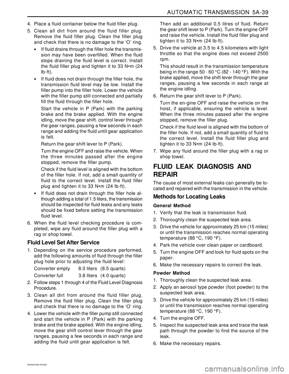
4. Place a fluid container below the fluid filler plug.
5. Clean all dirt from around the fluid filler plug.
Remove the fluid filler plug. Clean the filler plug
and check that there is no damage to the ‘O’ ring.
If fluid drains through the filler hole the transmis-
sion may have been overfilled. When the fluid
stops draining the fluid level is correct. Install
the fluid filler plug and tighten it to 33 Nm (24
lb-ft).
If fluid does not drain through the filler hole, the
transmission fluid level may be low. Install the
filler pump into the filler hole. Lower the vehicle
with the filler pump still connected and partially
fill the fluid through the filler hole.
Start the vehicle in P (Park) with the parking
brake and the brake applied. With the engine
idling, move the gear shift. control lever through
the gear ranges, pausing a few seconds in each
range and adding the fluid until gear application
is felt.
Return the gear shift lever to P (Park).
Turn the engine OFF and raise the vehicle. When
the three minutes passed after the engine
stopped, remove the filler pump.
Check if the fluid level is aligned with the bottom
of the filler hole. If not, add a small quantity of
fluid to the correct level. Install the fluid filler
plug and tighten it to 33 Nm (24 lb-ft).
If fluid does not drain through the filler hole al-
though adding a total of 1.5 liters, the transmission
should be inspected for fluid leaks and any leaks
should be fixed before setting the transmission
fluid level.
6. When the fluid level checking procedure is com-
pleted, wipe any fluid around the filler plug with a
rag or shop towel.
Fluid Level Set After Service
1. Depending on the service procedure performed,
add the following amounts of fluid through the filler
plug hole prior to adjusting the fluid level:
Converter empty 8.0 liters (8.5 quarts)
Converter full 3.8 liters (4.0 quarts)
2. Follow steps 1 through 4 of the Fluid Level Diagnosis
Procedure.
3. Clean all dirt from around the fluid filler plug.
Remove the fluid filler plug. Clean the filler plug
and check that there is no damage to the ‘O’ ring.
4. Lower the vehicle with the filler pump still connected
and start the vehicle in P (Park) with the parking
brake and the brake applied. With the engine idling,
move the gear shift control lever through the gear
ranges, pausing a few seconds in each range and
adding the fluid until gear application is felt.Then add an additional 0.5 litres of fluid. Return
the gear shift lever to P (Park). Turn the engine OFF
and raise the vehicle. Install the fluid filler plug and
tighten it to 33 Nm (24 lb-ft).
5. Drive the vehicle at 3.5 to 4.5 kilometers with light
throttle so that the engine does not exceed 2500
rpm.
This should result in the transmission temperature
being in the range 50 - 60 °C (82 - 140 °F). With the
brake applied, move the shift lever through the gear
ranges, pausing a few seconds in each range at
the engine idling.
6. Return the gear shift lever to P (Park).
Turn the en-gine OFF and raise the vehicle on the
hoist, if applicable, ensuring the vehicle is level.
When the three minutes passed after the engine
stopped, remove the filler plug.
Check if the fluid level is aligned with the bottom of
the filler hole. If not, add a small quantity of fluid to
the correct level. Install the fluid filler plug and
tighten it to 33 Nm (24 lb-ft).
7. Wipe any fluid around the filler plug with a rag or
shop towel.
FLUID LEAK DIAGNOSIS AND
REPAIR
The cause of most external leaks can generally be lo-
cated and repaired with the transmission in the vehicle.
Methods for Locating Leaks
General Method
1. Verify that the leak is transmission fluid.
2. Thoroughly clean the suspected leak area.
3. Drive the vehicle for approximately 25 km (15 miles)
or until the transmission reaches normal operating
temperature (88 °C, 190 °F).
4. Park the vehicle over clean paper or cardboard.
5. Turn the engine OFF and look for fluid spots on the
paper.
6. Make the necessary repairs to correct the leak.
Powder Method
1. Thoroughly clean the suspected leak area.
2. Apply an aerosol type powder (foot powder) to the
suspected leak area.
3. Drive the vehicle for approximately 25 km (15 miles)
or until the transmission reaches normal operating
temperature (88 °C, 190 °F).
4. Turn the engine OFF.
5. Inspect the suspected leak area and trace the leak
path through the powder to find the source of the
leak.
6. Make the necessary repairs.
Page 1134 of 2053
5A-40 AUTOMATIC TRANSMISSION
SSANGYONG MY2002
Dye and Black Light Method
1. Add dye to the transmission through the transmission
fluid filler plug. Follow the manufacturer’s recommen-
dation for the amount of dye to be used.
2. Use the black light to find the fluid leak.
3. Make the necessary repairs.
Repairing the Fluid Leak
Once the leak point is found the source of the leak
must be determined. The following list describes the
potential causes for the leak:
Fasteners are not torqued to specification.
Fastener threads and fastener holes are dirty or
corroded.
Gaskets, seals or sleeves are misaligned, damaged
or worn.
Damaged, warped or scratched seal bore or gasket
surface.
Loose or worn bearing causing excess seal or sleeve
wear.
Case or component porosity.
Fluid level is too high.
Plugged vent or damaged vent tube.
Water or coolant in fluid.
Fluid drain back holes plugged.
ELECTRICAL / GARAGE SHIFT
TEST
This preliminary test should be performed before a hoist
or road test to make sure electronic control inputs are
connected and operating. If the inputs are not checked
before operating the transmission, a simple electrical
condition could be misdiagnosed as a major
transmission condition.
A scan tool provides valuable information and must
be used on the automatic transmission for accurate
diagnosis.
1. Move gear shift control lever to P (Park) and set
the parking brake.
2. Connect scan tool to Data Link Connector (DLC)
terminal.
3. Start engine.
4. Turn the scan tool ON.
5. Verify that the appropriate signals are present.
These signals may include:
ENGINE SPEED
VEHICLE SPEED
THROTTLE POSITION
ACCEL. PEDAL POSITION
TRANSMISSION GEAR STATE
GEAR SHIFT LEVER POSITION
TRANSMISSION FLUID TEMPERATURE
CLOSED THROTTLE POSITION LEARN
OPEN THROTTLE POSITION LEARNT
CLOSED ACCEL. PEDAL POSITION LEARNT
OPEN ACCEL. PEDAL POSITION LEARNT
A/C COMPRESSOR STATUS
KICKDOWN SWITCH STATUS
4WD STATUS
MODE SWITCH
THROTTLE POSITION VOLTAGE
GEAR SHIFT LEVER POSITION VOLTAGE
TRANS. FLUID TEMPERATURE VOLTAGE
A/C SWITCH
KICKDOWN SWITCH VOLTAGE
4WD LAMP LOW VOLTAGE
4WD LAMP HIGH VOLTAGE
MODE SWITCH VOLTAGE
BATTERY VOLTAGE
6. Monitor the A/C COMPRESSOR STATUS signal
while pushing the A/C switch.
The A/C COMPRESSOR STATUS should come
ON when the A/C switch is pressed, and turn
OFF when the A/C switch is repushed.
7. Monitor the GEAR SHIFT LEVER POSITION signal
and move the gear shift control lever through all
the ranges.
Verify that the GEAR SHIFT LEVER POSITION
value matches the gear range indicated on the
instrument panel or console.
Gear selections should be immediate and not
harsh.
8. Move gear shift control lever to neutral and monitor
the THROTTLE POSITION signal while increasing
and decreasing engine speed with the accelerator
pedal.
THROTTLE POSITION should increase with en-
gine speed.
ROAD TEST PROCEDURE
Perform the road test using a scan tool.
This test should be performed when traffic and road
conditions permit.
Observe all traffic regulations.
ELECTRONIC ADJUSTMENTS
Idle Speed Adjustments
Carry out the adjustments to the idle speed as detailed
in the workshop manual.
Vehicle Coding
The vehicle coding is integrated as part of the
diagnostic software. A scan tool has the function to
code the ve-hicle through the K-line.
Page 1135 of 2053
5A-40 AUTOMATIC TRANSMISSION
SSANGYONG MY2002
Dye and Black Light Method
1. Add dye to the transmission through the transmission
fluid filler plug. Follow the manufacturer’s recommen-
dation for the amount of dye to be used.
2. Use the black light to find the fluid leak.
3. Make the necessary repairs.
Repairing the Fluid Leak
Once the leak point is found the source of the leak
must be determined. The following list describes the
potential causes for the leak:
Fasteners are not torqued to specification.
Fastener threads and fastener holes are dirty or
corroded.
Gaskets, seals or sleeves are misaligned, damaged
or worn.
Damaged, warped or scratched seal bore or gasket
surface.
Loose or worn bearing causing excess seal or sleeve
wear.
Case or component porosity.
Fluid level is too high.
Plugged vent or damaged vent tube.
Water or coolant in fluid.
Fluid drain back holes plugged.
ELECTRICAL / GARAGE SHIFT
TEST
This preliminary test should be performed before a hoist
or road test to make sure electronic control inputs are
connected and operating. If the inputs are not checked
before operating the transmission, a simple electrical
condition could be misdiagnosed as a major
transmission condition.
A scan tool provides valuable information and must
be used on the automatic transmission for accurate
diagnosis.
1. Move gear shift control lever to P (Park) and set
the parking brake.
2. Connect scan tool to Data Link Connector (DLC)
terminal.
3. Start engine.
4. Turn the scan tool ON.
5. Verify that the appropriate signals are present.
These signals may include:
ENGINE SPEED
VEHICLE SPEED
THROTTLE POSITION
ACCEL. PEDAL POSITION
TRANSMISSION GEAR STATE
GEAR SHIFT LEVER POSITION
TRANSMISSION FLUID TEMPERATURE
CLOSED THROTTLE POSITION LEARN
OPEN THROTTLE POSITION LEARNT
CLOSED ACCEL. PEDAL POSITION LEARNT
OPEN ACCEL. PEDAL POSITION LEARNT
A/C COMPRESSOR STATUS
KICKDOWN SWITCH STATUS
4WD STATUS
MODE SWITCH
THROTTLE POSITION VOLTAGE
GEAR SHIFT LEVER POSITION VOLTAGE
TRANS. FLUID TEMPERATURE VOLTAGE
A/C SWITCH
KICKDOWN SWITCH VOLTAGE
4WD LAMP LOW VOLTAGE
4WD LAMP HIGH VOLTAGE
MODE SWITCH VOLTAGE
BATTERY VOLTAGE
6. Monitor the A/C COMPRESSOR STATUS signal
while pushing the A/C switch.
The A/C COMPRESSOR STATUS should come
ON when the A/C switch is pressed, and turn
OFF when the A/C switch is repushed.
7. Monitor the GEAR SHIFT LEVER POSITION signal
and move the gear shift control lever through all
the ranges.
Verify that the GEAR SHIFT LEVER POSITION
value matches the gear range indicated on the
instrument panel or console.
Gear selections should be immediate and not
harsh.
8. Move gear shift control lever to neutral and monitor
the THROTTLE POSITION signal while increasing
and decreasing engine speed with the accelerator
pedal.
THROTTLE POSITION should increase with en-
gine speed.
ROAD TEST PROCEDURE
Perform the road test using a scan tool.
This test should be performed when traffic and road
conditions permit.
Observe all traffic regulations.
ELECTRONIC ADJUSTMENTS
Idle Speed Adjustments
Carry out the adjustments to the idle speed as detailed
in the workshop manual.
Vehicle Coding
The vehicle coding is integrated as part of the
diagnostic software. A scan tool has the function to
code the ve-hicle through the K-line.
Page 1664 of 2053
BODY WIRING SYSTEM 9A-13
SSANGYONG MY2002
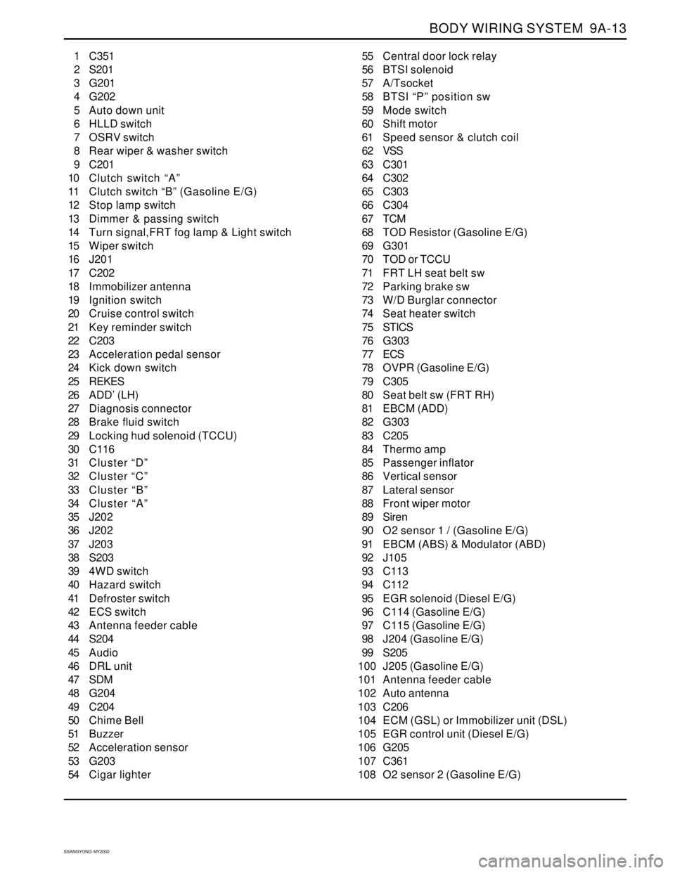
1 C351
2 S201
3 G201
4 G202
5 Auto down unit
6 HLLD switch
7 OSRV switch
8 Rear wiper & washer switch
9 C201
10 Clutch switch “A”
11 Clutch switch “B” (Gasoline E/G)
12 Stop lamp switch
13 Dimmer & passing switch
14 Turn signal,FRT fog lamp & Light switch
15 Wiper switch
16 J201
17 C202
18 Immobilizer antenna
19 Ignition switch
20 Cruise control switch
21 Key reminder switch
22 C203
23 Acceleration pedal sensor
24 Kick down switch
25 REKES
26 ADD’ (LH)
27 Diagnosis connector
28 Brake fluid switch
29 Locking hud solenoid (TCCU)
30 C116
31 Cluster “D”
32 Cluster “C”
33 Cluster “B”
34 Cluster “A”
35 J202
36 J202
37 J203
38 S203
39 4WD switch
40 Hazard switch
41 Defroster switch
42 ECS switch
43 Antenna feeder cable
44 S204
45 Audio
46 DRL unit
47 SDM
48 G204
49 C204
50 Chime Bell
51 Buzzer
52 Acceleration sensor
53 G203
54 Cigar lighter55 Central door lock relay
56 BTSI solenoid
57 A/Tsocket
58 BTSI “P” position sw
59 Mode switch
60 Shift motor
61 Speed sensor & clutch coil
62 VSS
63 C301
64 C302
65 C303
66 C304
67 TCM
68 TOD Resistor (Gasoline E/G)
69 G301
70 TOD or TCCU
71 FRT LH seat belt sw
72 Parking brake sw
73 W/D Burglar connector
74 Seat heater switch
75 STICS
76 G303
77 ECS
78 OVPR (Gasoline E/G)
79 C305
80 Seat belt sw (FRT RH)
81 EBCM (ADD)
82 G303
83 C205
84 Thermo amp
85 Passenger inflator
86 Vertical sensor
87 Lateral sensor
88 Front wiper motor
89 Siren
90 O2 sensor 1 / (Gasoline E/G)
91 EBCM (ABS) & Modulator (ABD)
92 J105
93 C113
94 C112
95 EGR solenoid (Diesel E/G)
96 C114 (Gasoline E/G)
97 C115 (Gasoline E/G)
98 J204 (Gasoline E/G)
99 S205
100 J205 (Gasoline E/G)
101 Antenna feeder cable
102 Auto antenna
103 C206
104 ECM (GSL) or Immobilizer unit (DSL)
105 EGR control unit (Diesel E/G)
106 G205
107 C361
108 O2 sensor 2 (Gasoline E/G)
Page 1675 of 2053
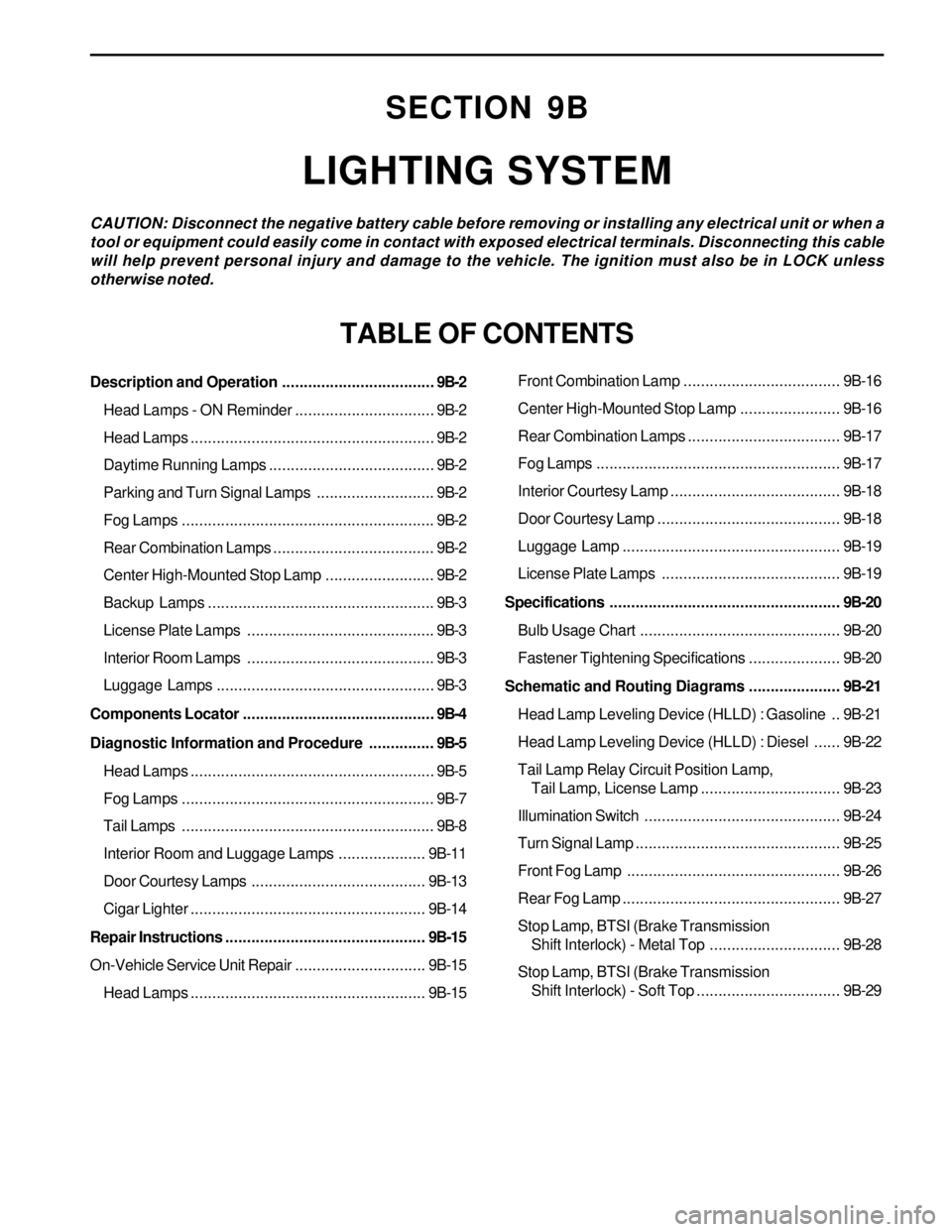
SECTION 9B
LIGHTING SYSTEM
CAUTION: Disconnect the negative battery cable before removing or installing any electrical unit or when a
tool or equipment could easily come in contact with exposed electrical terminals. Disconnecting this cable
will help prevent personal injury and damage to the vehicle. The ignition must also be in LOCK unless
otherwise noted.
TABLE OF CONTENTS
Description and Operation...................................9B-2
Head Lamps - ON Reminder................................9B-2
Head Lamps........................................................9B-2
Daytime Running Lamps......................................9B-2
Parking and Turn Signal Lamps...........................9B-2
Fog Lamps..........................................................9B-2
Rear Combination Lamps.....................................9B-2
Center High-Mounted Stop Lamp.........................9B-2
Backup Lamps....................................................9B-3
License Plate Lamps ...........................................9B-3
Interior Room Lamps ...........................................9B-3
Luggage Lamps..................................................9B-3
Components Locator............................................9B-4
Diagnostic Information and Procedure...............9B-5
Head Lamps........................................................9B-5
Fog Lamps..........................................................9B-7
Tail Lamps..........................................................9B-8
Interior Room and Luggage Lamps....................9B-11
Door Courtesy Lamps ........................................9B-13
Cigar Lighter......................................................9B-14
Repair Instructions..............................................9B-15
On-Vehicle Service Unit Repair..............................9B-15
Head Lamps......................................................9B-15Front Combination Lamp....................................9B-16
Center High-Mounted Stop Lamp.......................9B-16
Rear Combination Lamps...................................9B-17
Fog Lamps........................................................9B-17
Interior Courtesy Lamp .......................................9B-18
Door Courtesy Lamp ..........................................9B-18
Luggage Lamp..................................................9B-19
License Plate Lamps .........................................9B-19
Specifications.....................................................9B-20
Bulb Usage Chart..............................................9B-20
Fastener Tightening Specifications.....................9B-20
Schematic and Routing Diagrams.....................9B-21
Head Lamp Leveling Device (HLLD) : Gasoline ..9B-21
Head Lamp Leveling Device (HLLD) : Diesel......9B-22
Tail Lamp Relay Circuit Position Lamp,
Tail Lamp, License Lamp................................9B-23
Illumination Switch.............................................9B-24
Turn Signal Lamp...............................................9B-25
Front Fog Lamp.................................................9B-26
Rear Fog Lamp..................................................9B-27
Stop Lamp, BTSI (Brake Transmission
Shift Interlock) - Metal Top..............................9B-28
Stop Lamp, BTSI (Brake Transmission
Shift Interlock) - Soft Top.................................9B-29
Page 1676 of 2053
SSANGYONG MY2002
9B-2 LIGHTING SYSTEM
DESCRIPTION AND OPERATION
HEAD LAMPS - ON REMINDER
When the headlamp switch is in the headlamps-on or
parkinglamps-on positions, voltage is applied to the
chime module. With the headlamp switch on and the
driver’s side door open, the module loses voltage. The
module senses this change. If voltage is still available,
it is applied to sound the chime. The chime can be
turned off by turning the headlamp switch off or closing
the driver’s side door. To replace the chime module,
refer to Section 9E, Instrumentation / Driver Information.
HEAD LAMPS
The headlamps are controlled by the multifunction lever
on the left side of the steering column. They will come
on with the ignition switch in on position. Turning the
headlamp switch to the first position turns on the
parking lamps, the license plate lamps, and the
instrument panel illumination. Turning the switch to the
second position turns on all of the previous lamps and
the headlamps. Turning the switch off turns off all the
lamps.
The headlamps high beam and low beams are also
controlled by this lever. When the headlamps are on,
pushing the lever away from the driver until the switch
clicks changes the lamp from low beam to high beam.
An indicator lamp on the instrument cluster assembly
will come on when the high beam headlamps are on.
To return the headlamps to low beams, pull the lever
toward the driver.
The headlamps must be aimed for proper illumination
of the road. Headlamp aim should be checked
whenever a new headlamp assembly is installed or
when service or repairs to the front end may have
disturbed the headlamp assembly or its mountings.
DAYTIME RUNNING LAMPS
The daytime running lamps (DRL) will illuminate under
the following conditions:
The ignition is ON.
The light switch is OFF.
The parking brake is released.
When the head lamps are on, the DRL will turn off.
To turn the DRL off when idling, apply the parking
brake.
PARKING AND TURN SIGNAL
LAMPS
The parking lamps can be turned on by turning the
headlamp switch to the first position. The parking lamps
can be turned off by turning the switch off.
When the turn signals are activated, the appropriate
turn signal lamps flash to signal a turn. The front, the
rear, work only when the ignition is on.
The front and rear turn signals are controlled by the
multifunction lever on the left side of the steering
column. Moving the lever all the way up or down past
the detent will turn on the turn signals. When the turn
is complete, the lever will automatically be release,
and the front and the rear turn signals will stop flashing.
For changing lanes or shallow turns in which the steering
wheel does not turn far enough to cancel the signal,
move the signal to the first detent and hold it there.
The turn signal will cancel when the lever is released.
FOG LAMPS
The fog lamp switch is located in multifunction lever
on the right side of steering column. To use the fog
lamps, first turn on the parking lamps. Then, turning
the fog lamps switch on position. The indicator light in
the instrument cluster will illuminate to indicate that
the fog lamps are on. Turning the switch again to turn
off the fog lamps. The indicator light will then go off.
The fog lamps must be aimed for proper illumination
of the road. Fog lamp aim should be checked when a
new bulb is installed or if service or repairs to the front
end may have disturbed the fog lamp assembly or its
mountings.
REAR COMBINATION LAMPS
The taillamps, stoplamps, backup lamps and turn
signals are one assembly.
Turning on either the headlamps or the parking lamps
will also turn on the taillamps. When the brake pedal
is pushed, the taillamps will glow more brightly to serve
as stop lamps.
CENTER HIGH-MOUNTED STOP
LAMP
The center high-mounted stoplamp is on the tail gate
and will come on when the brake pedal is pressed.
Page 1751 of 2053
SSANGYONG MY2002
9G-2 INTERIOR TRIM
DESCRIPTION AND OPERATION
INTERIOR TRIM PANELS
The interior trim panels are molded plastic and fasten
with screws or plastic clips.
FLOOR CARPET
The floor carpets are divided front and rear floor carpet.
FLOOR CONSOLE
The floor console fits over the tunnel in the floor of the
vehicle and extends from under the center of the
instrument panel to the rear seat area. The floor console
contains the transaxle shift lever, parking brake lever,
a storage compartment and coin storage