Page 1584 of 2053
SSANGYONG MY2002
8A-8 SEAT BELTS
N•m
19
45
45
45Lb-Ft
14
33
33
33 Child Seat Tether Anchor Bolt
Seat Belt Anchor Bolt
Seat Belt Height Adjuster Bolt
Seat Belt Retractor BoltLb-In
-
-
-
-Application
SPECIFICATIONS
FASTENER TIGHTENING SPECIFICATIONS
Page 1640 of 2053

SSANGYONG MY2002
8B-58 SUPPLEMENTAL RESTRAINTS SYSTEM
REPAIR INSTRUCTION
ON-VEHICLE SERVICE
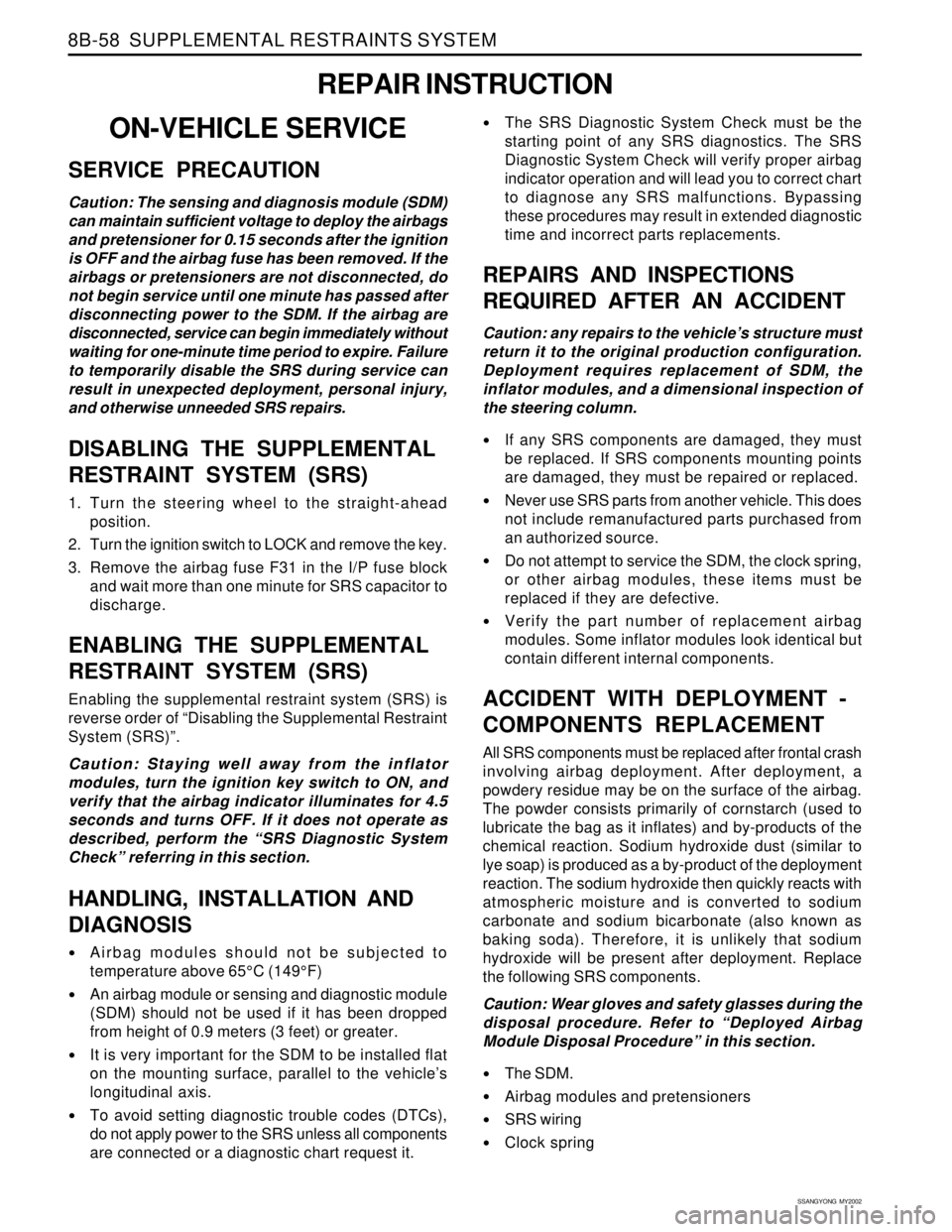
SERVICE PRECAUTION
Caution: The sensing and diagnosis module (SDM)
can maintain sufficient voltage to deploy the airbags
and pretensioner for 0.15 seconds after the ignition
is OFF and the airbag fuse has been removed. If the
airbags or pretensioners are not disconnected, do
not begin service until one minute has passed after
disconnecting power to the SDM. If the airbag are
disconnected, service can begin immediately without
waiting for one-minute time period to expire. Failure
to temporarily disable the SRS during service can
result in unexpected deployment, personal injury,
and otherwise unneeded SRS repairs.
DISABLING THE SUPPLEMENTAL
RESTRAINT SYSTEM (SRS)
1. Turn the steering wheel to the straight-ahead
position.
2. Turn the ignition switch to LOCK and remove the key.
3. Remove the airbag fuse F31 in the I/P fuse block
and wait more than one minute for SRS capacitor to
discharge.
ENABLING THE SUPPLEMENTAL
RESTRAINT SYSTEM (SRS)
Enabling the supplemental restraint system (SRS) is
reverse order of “Disabling the Supplemental Restraint
System (SRS)”.
Caution: Staying well away from the inflator
modules, turn the ignition key switch to ON, and
verify that the airbag indicator illuminates for 4.5
seconds and turns OFF. If it does not operate as
described, perform the “SRS Diagnostic System
Check” referring in this section.
HANDLING, INSTALLATION AND
DIAGNOSIS
Airbag modules should not be subjected to
temperature above 65°C (149°F)
An airbag module or sensing and diagnostic module
(SDM) should not be used if it has been dropped
from height of 0.9 meters (3 feet) or greater.
It is very important for the SDM to be installed flat
on the mounting surface, parallel to the vehicle’s
longitudinal axis.
To avoid setting diagnostic trouble codes (DTCs),
do not apply power to the SRS unless all components
are connected or a diagnostic chart request it.
The SRS Diagnostic System Check must be the
starting point of any SRS diagnostics. The SRS
Diagnostic System Check will verify proper airbag
indicator operation and will lead you to correct chart
to diagnose any SRS malfunctions. Bypassing
these procedures may result in extended diagnostic
time and incorrect parts replacements.
REPAIRS AND INSPECTIONS
REQUIRED AFTER AN ACCIDENT
Caution: any repairs to the vehicle’s structure must
return it to the original production configuration.
Deployment requires replacement of SDM, the
inflator modules, and a dimensional inspection of
the steering column.
If any SRS components are damaged, they must
be replaced. If SRS components mounting points
are damaged, they must be repaired or replaced.
Never use SRS parts from another vehicle. This does
not include remanufactured parts purchased from
an authorized source.
Do not attempt to service the SDM, the clock spring,
or other airbag modules, these items must be
replaced if they are defective.
Verify the part number of replacement airbag
modules. Some inflator modules look identical but
contain different internal components.
ACCIDENT WITH DEPLOYMENT -
COMPONENTS REPLACEMENT
All SRS components must be replaced after frontal crash
involving airbag deployment. After deployment, a
powdery residue may be on the surface of the airbag.
The powder consists primarily of cornstarch (used to
lubricate the bag as it inflates) and by-products of the
chemical reaction. Sodium hydroxide dust (similar to
lye soap) is produced as a by-product of the deployment
reaction. The sodium hydroxide then quickly reacts with
atmospheric moisture and is converted to sodium
carbonate and sodium bicarbonate (also known as
baking soda). Therefore, it is unlikely that sodium
hydroxide will be present after deployment. Replace
the following SRS components.
Caution: Wear gloves and safety glasses during the
disposal procedure. Refer to “Deployed Airbag
Module Disposal Procedure” in this section.
The SDM.
Airbag modules and pretensioners
SRS wiring
Clock spring
Page 1770 of 2053

SSANGYONG MY2002
9I-2 WATERLEAKS
Description
SPECIFICATIONS
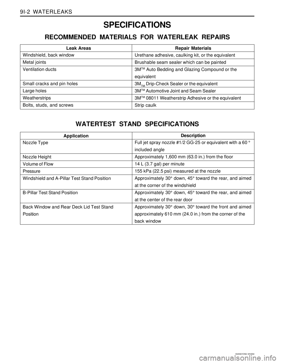
RECOMMENDED MATERIALS FOR WATERLEAK REPAIRS
WATERTEST STAND SPECIFICATIONS
Windshield, back window
Metal joints
Ventilation ducts
Small cracks and pin holes
Large holes
Weatherstrips
Bolts, studs, and screwsLeak Areas Repair MaterialsUrethane adhesive, caulking kit, or the equivalent
Brushable seam sealer which can be painted
3M
TM Auto Bedding and Glazing Compound or the
equivalent
3M
TM Drip-Check Sealer or the equivalent
3M
TM Automotive Joint and Seam Sealer
3M
TM 08011 Weatherstrip Adhesive or the equivalent
Strip caulk
Nozzle Type
Nozzle Height
Volume of Flow
Pressure
Windshield and A-Pillar Test Stand Position
B-Pillar Test Stand Position
Back Window and Rear Deck Lid Test Stand
PositionApplication
Full jet spray nozzle #1/2 GG-25 or equivalent with a 60 °
included angle
Approximately 1,600 mm (63.0 in.) from the floor
14 L (3.7 gal) per minute
155 kPa (22.5 psi) measured at the nozzle
Approximately 30° down, 45° toward the rear, and aimed
at the corner of the windshield
Approximately 30° down, 45° toward the rear, and aimed
at the center of the rear door
Approximately 30° down, 30° toward the front and aimed
approximately 610 mm (24.0 in.) from the corner of the
back window
Page 1771 of 2053

WATERLEAKS 9I-3
SSANGYONG MY2002
DIAGNOSIS
WATERLEAK DIAGNOSIS
The repair of waterleaks in the body requires proper
testing and diagnosis. Repair waterleaks by adjusting
the misaligned parts and using the proper repair materi-
als. First, determine what conditions cause the leak.
For example, the leak may occur only when the vehicle
is parked on an incline, or water may appear only in
the spare tire compartment. Second, test the area for
the source of the leak using the following testing
methods. If the general leak area is found, determine
the exact entry point of the leak by using a water hose
or an air hose. If the general leak area is not obvious,
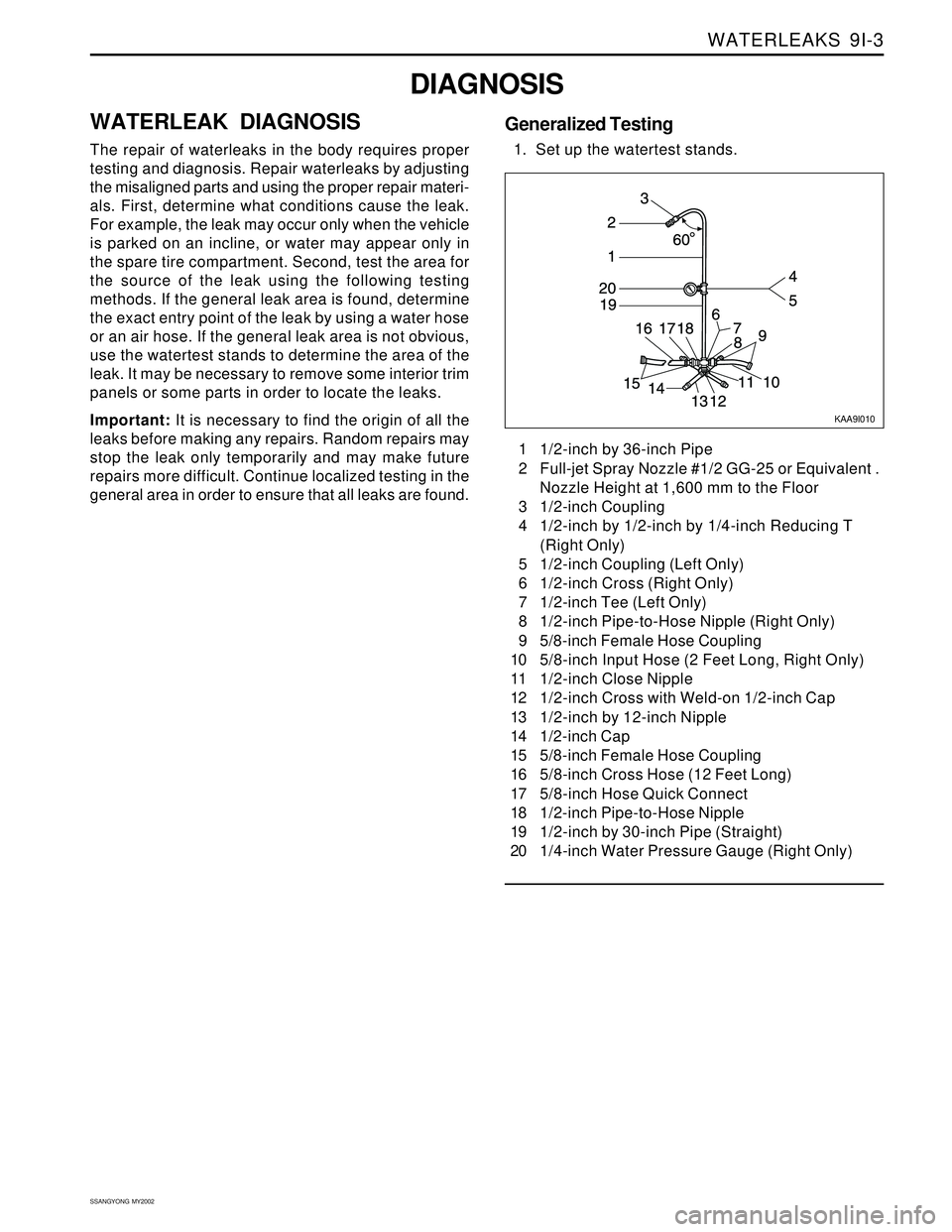
use the watertest stands to determine the area of the
leak. It may be necessary to remove some interior trim
panels or some parts in order to locate the leaks.
Important: It is necessary to find the origin of all the
leaks before making any repairs. Random repairs may
stop the leak only temporarily and may make future
repairs more difficult. Continue localized testing in the
general area in order to ensure that all leaks are found.1 1/2-inch by 36-inch Pipe
2 Full-jet Spray Nozzle #1/2 GG-25 or Equivalent .
Nozzle Height at 1,600 mm to the Floor
3 1/2-inch Coupling
4 1/2-inch by 1/2-inch by 1/4-inch Reducing T
(Right Only)
5 1/2-inch Coupling (Left Only)
6 1/2-inch Cross (Right Only)
7 1/2-inch Tee (Left Only)
8 1/2-inch Pipe-to-Hose Nipple (Right Only)
9 5/8-inch Female Hose Coupling
10 5/8-inch Input Hose (2 Feet Long, Right Only)
11 1/2-inch Close Nipple
12 1/2-inch Cross with Weld-on 1/2-inch Cap
13 1/2-inch by 12-inch Nipple
14 1/2-inch Cap
15 5/8-inch Female Hose Coupling
16 5/8-inch Cross Hose (12 Feet Long)
17 5/8-inch Hose Quick Connect
18 1/2-inch Pipe-to-Hose Nipple
19 1/2-inch by 30-inch Pipe (Straight)
20 1/4-inch Water Pressure Gauge (Right Only)
KAA9I010
Generalized Testing
1. Set up the watertest stands.