Page 835 of 2053

FRONT SUSPENSION 2C-7
SSANGYONG MY2002
TORSION BAR
Removal and Installation Procedure
1. Raise and suitably support the vehicle.
2. Remove the height control bolt.
Notice:
Install the torsion bar and adjust the distance
be tween the end of the height control blot and
piece end of the bolt to be 50 - 55 mm (1.97 -
2.17 inch). Adjust the vehicle height.
KAA2C110
KAA2C120
KAA2C130
3. Remove the torsion bar fixing nuts and bolts and
then withdraw the torsion bar.
Installation Notice
Check and adjust the wheel alignment.
4. Installation should follow the removal procedure
in the reverse order.
LOWER CONTROL ARM
Tools Required
661 589 13 33 00 Ball Joint Remover
Removal and Installation Procedure
1. Raise and suitably support the vehicle.
2. Remove the front wheels. Refer to Section 2E,
Tires and Wheels.
3. Remove the torsion bar. Refer to “Torsion Bar” in
this section.
4. Remove the front shock absorber lower mounting
bolt and nut.
Installation Notice
Tightening Torque 70 Nm (52 lb-ft)
Tightening
TorqueM10
M1250 Nm (37 lb-ft)
70 Nm (52 lb-ft)
Page 848 of 2053
REAR SUSPENSION 2D-3
SSANGYONG MY2002
DIAGNOSTIC INFORMATION AND PROCEDURES
EXCESSIVE FRICTION CHECK
Ball Joint Inspection
Check excessive friction in the rear suspension as fol-
lows:
1. With the aid of a helper, lift up on the rear bumper
and raise the vehicle as high as possible. Slow
release the bumper and allow the car to assume
normal trim height.
2. Measure the distance from the floor to the center
of the bumper.3. Push down on the bumper, release slowly, and
allow the car to assume normal trim height.
4. Measure the distance from the floor to the center
of the bumper.
The distance between the two measurements should
be less than 12.7 mm (0.50 inch). If the difference
exceeds this limit, inspect the control arms for damage
or wear.
Page 928 of 2053

SSAMGYONG MY2002
4A-8 HYDRAULIC BRAKES
YAD4A170
YAD4A180
LCRV (LOAD CONSCIOUS
REDUCING VALVE)
LCRV consists of sensing part and hydraulic control
part.
1. Sensing Part
It detects the changes of vehicle height caused
by vehicle load. It consists of load sensing spring
and control lever which change according to
vehicle load.
2. Hydraulic Control Part
It consists of valve stem devices which controls
hydraulic pressure according to load detected by
sensing part.
YAD4A190
4. Place alignment marks between the lock nut (b)
and adjusting screw (c) after the valve setting.
5. LCRV setting should be performed with unloaded
vehicle condition.
Setting Method
1. Install the connecting rod (a) to the No.1 hole.
2. Adjust the clearance “X” to be 0mm and tighten
the bolt (c) using the lock nut (b).
Installation Notice
Tightening Torque14 - 18 Nm
(10 - 13 lb-ft)
3. Remove the connecting rod (a) from the No.1 hole
and reinstall it to the No.2 hole.
Installation Notice
Tightening Torque14 - 18 Nm
(10 - 13 lb-ft)
Page 1363 of 2053
SSAMGYONG MY2002
5C-8 CLUTCH
5. Unscrew the bolts and remove the clutch cover,
pressure plate and clutch disc.
Notice: Be careful not to drop the pressure plate
and clutch disc.
Installation Notice
6. Installation should follow the removal procedure
in the reverse order.
Notice:
Before installation, clean oil and grease on the
flywheel surface.
Do not clean the clutch disc and release bearing
in solvent.
2. Clutch Disc
Check the facing for rivet looseness, excessive
runout, sticks, oil and grease.
Measure the rivet head depth.
If out limit, replace the disc.
Inspection Procedure
1. Clutch Cover
Check the diaphragm spring tip for wear and
height unevenness.
Check the pressure plate surface for wear, crack
and discoloration.
Check the strap plate rivet for looseness and
replace the clutch cover if loosened.
KAA5C090
KAA5C100
KAA5C110
Tightening Torque21 - 27 Nm
(15 - 20 lb-ft)
Wear Limit 0.3 mm
Unevenness Limit 0.8 mm
Page 1368 of 2053
CLUTCH 5C-13
SSANGYONG MY2002
Inspection Procedure
1. Pedal Stroke (A).
Installation Notice
Notice: To adjust the pedal stroke, loosen the lock
nut (H) of the interlock switch (G) and turn the two
lock auto until the stroke is correct.
2. Pedal Height (B).
Installation Notice
Notice: To adjust the pedal height, loosen the lock
nut (C) of the stopper bolt (D) and turn the stopper
bolt until the height is correct.
3. Pedal Free Play (E).
Installation Notice
Notice: To adjust the pedal free play, loosen the
lock nut (F) of the master cylinder and turn the
push rod until the free play is correct.
4. Check the fulcrum pin and the bushing for wear,
the pedal for bending and the spring for damage.
KAA5C160
Max. Stroke 158 mm
Height
(From the Floor Carpet)147 - 187 mm
Free Play 5 - 10 mm
Page 1577 of 2053

SECTION 8A
SEAT BELTS
CAUTION: Disconnect the negative battery cable before removing or installing any electrical unit or when a
tool or equipment could easily come in contact with exposed electrical terminals. Disconnecting this cable
will help prevent personal injury and damage to the vehicle. The ignition must be in B unless otherwise
noted.
TABLE OF CONTENTS
Description and Operation...................................8A-2
Driver Seat Belt Warning......................................8A-2
Three-Point Front Seat Belt With Pretensioner.......8A-2
Three-Point Rear Outboard Seat Belt....................8A-2
Two-Point Lap Rear Center Seat Belt....................8A-2
Operational and Functional Checks......................8A-2
Child Seat Tether Anchor.....................................8A-2
Component Locator.............................................8A-3
Front Seat Belt.....................................................8A-3
Rear Seat Belt.....................................................8A-4Repair Procedures...............................................8A-5
On-Vehicle Service.................................................8A-5
Three-Point Front Seat Belt With Pretensioner.......8A-5
Front Seat Belt Height Adjuster............................8A-6
Three-Point Rear Outboard Seat Belt....................8A-6
Two-Point Lap Rear Center Seat Belt....................8A-7
Child Seat Tether Anchor.....................................8A-7
Specifications.......................................................8A-8
Fastener Tightening Specifications.......................8A-8
Schematic and Routing Diagrams.......................8A-9
Seat Belt & Tension Reducer...............................8A-9
Page 1579 of 2053
SEAT BELTS 8A-3
SSANGYONG MY2002
COMPONENTS LOCATOR
FRONT SEAT BELT
1 Front Seat Belt Height Adjuster
2 Front Seat Belt Upper Anchor
3 Front Seat Belt With Pretensioner
4 Buckle Assembly
5 Front Seat Belt Lower Anchor6 Seat Belt Retractor Bolt
7 Seat Belt Retractor With Pretensioner
8 Seat Belt Dust Cover and Screw
9 Seat Belt Webbing Guide
KAA8A010
Page 1582 of 2053

SSANGYONG MY2002
8A-6 SEAT BELTS
KAA8A070
KAA8A060
KAA8A050
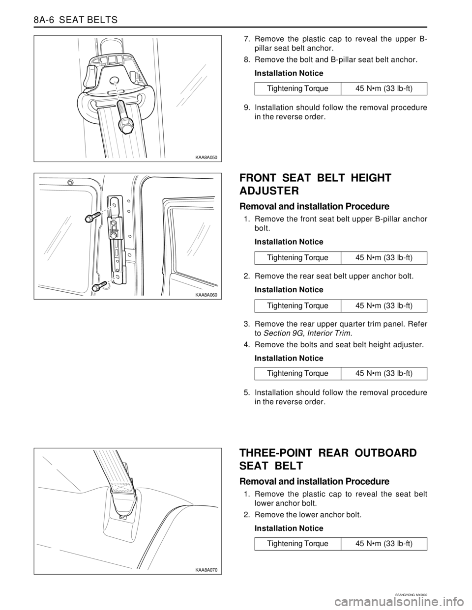
7. Remove the plastic cap to reveal the upper B-
pillar seat belt anchor.
8. Remove the bolt and B-pillar seat belt anchor.
Installation Notice
9. Installation should follow the removal procedure
in the reverse order.
Tightening Torque 45 Nm (33 lb-ft)
FRONT SEAT BELT HEIGHT
ADJUSTER
Removal and installation Procedure
1. Remove the front seat belt upper B-pillar anchor
bolt.
Installation Notice
2. Remove the rear seat belt upper anchor bolt.
Installation Notice
3. Remove the rear upper quarter trim panel. Refer
to Section 9G, Interior Trim.
4. Remove the bolts and seat belt height adjuster.
Installation Notice
5. Installation should follow the removal procedure
in the reverse order.
THREE-POINT REAR OUTBOARD
SEAT BELT
Removal and installation Procedure
1. Remove the plastic cap to reveal the seat belt
lower anchor bolt.
2. Remove the lower anchor bolt.
Installation Notice
Tightening Torque 45 Nm (33 lb-ft)
Tightening Torque 45 Nm (33 lb-ft)
Tightening Torque 45 Nm (33 lb-ft)
Tightening Torque 45 Nm (33 lb-ft)