Page 515 of 2053

M161 ENGINE CONTROLS 1F2 -- 97
D AEW OO M Y_2000
KAA1F370
FUEL TANK
Removal and Installation Procedure
Caution: The fuel system is under pressure. To
avoid fuel spillage and the risk of personal injury or
fire, it is necessary to relieve the fuel system pres -
sure before disconnecting the fuel lines.
1. Relieve the fuel pressure. Refer to “Discharging the
Pressure in Fuel System” in this section.
2. Disconnect the negative battery cable.
3. Drain the fuel tank.
4. Put aside the floor carpet to remove the fuel pump
access cover.
5. Remove the fuel pump access cover.
YAA1F170
6. Disconnect the return line.
7. Disconnect the supply line.
8. Disconnect the fuel tank-to-canister hose from the
fuel tank.
9. Disconnect the fuel pump wiring connector.
KAB1F370
10. Disconnect the fuel filler hose and air vent hose from
the fuel tank.
11. Support the fuel tank.
12. Remove the fuel tank retaining nuts.
Installation Notice
Tightening Torque
38 NSm (28 lb-ft)
13. Carefully lower the fuel tank.
Page 518 of 2053

1F2 -- 100 M161 ENGINE CONTROLS
D AEW OO M Y_2000
YAA1F770
Notice:Before removal, the fuel rail assembly may be
cleaned with a spray-type cleaner, following package in-
structions. Do not immerse the fuel rails in liquid clean-
ing solvent. Use care in removing the fuel rail assembly
to prevent damage to the electrical connectors and in-
jector spray tips. Prevent dirt and other contaminants
from entering open lines and passages. Fittings should
be capped and holes plugged during service.
Important:If an injector becomes separated from the
rail and remains in the cylinder head, replace the injector
O-ring seals and the retaining clip.
12. Remove the injectors and the fuel rail carefully.
13. Remove the fuel injector retainer clips.
14. Remove the fuel injectors by pulling them down and
out.
15. Discard the fuel injector O-rings.
16. Lubricate the new fuel injector O-rings with engine
oil. Install the new O-rings on the fuel injectors.
17. Perform a leak check of the fuel rail and fuel injec-
tors.
18. Installation should follow the removal procedure in
the reverse order.
YAA1F780
ENGINE COOLANT TEMPERATURE
SENSOR
Removal and Installation Procedure
1. Relieve the coolant system pressure.
2. Disconnect the negative battery cable.
3. Disconnect the engine coolant temperature sensor
connector.
Notice:Take care when handling the engine coolant
temperature sensor. Damage to the sensor will affect
the proper operation of the fuel injection system.
4. Remove the engine coolant temperature sensor
from the pump hosing.
Installation Notice
Tightening Torque
30 NSm (22 Ib-ft)
5. Installation should follow the removal procedure in
the reverse order.
Page 537 of 2053
1A3 -- 2 GENERAL ENGINE INFORMATION
D AEW OO M Y_2000
ENGINE SPECIFICATIONS (Cont’d)
ApplicationOM662LAOM661LA
Idle Speed (rpm)720 -- 820750 -- 850
Fuel Injection Pressure (bar)135 -- 143135 -- 143
Oil Capacity (liter)8.0 -- 9.56.5 -- 8.0
Lubrication TypeForced by Gear PumpForced by Gear Pump
Oil Filter TypeCombined Full-- Flow and Partial
Flow FilterCombined Full-- Flow and Partial
Flow Filter
FuelDieselDiesel
Page 547 of 2053

1A3 -- 12 GENERAL ENGINE INFORMATION
D AEW OO M Y_2000
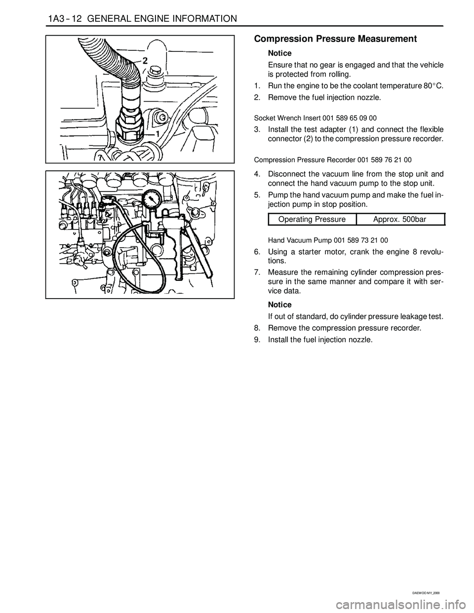
Compression Pressure Measurement
Notice
Ensure that no gear is engaged and that the vehicle
is protected from rolling.
1. Run the engine to be the coolant temperature 80_C.
2. Remove the fuel injection nozzle.
Socket Wrench Insert 001 589 65 09 00
3. Install the test adapter (1) and connect the flexible
connector (2) to the compression pressure recorder.
Compression Pressure Recorder 001 589 76 21 00
4. Disconnect the vacuum line from the stop unit and
connect the hand vacuum pump to the stop unit.
5. Pump the hand vacuum pump and make the fuel in-
jection pump in stop position.
Operating PressureApprox. 500bar
Hand Vacuum Pump 001 589 73 21 00
6. Using a starter motor, crank the engine 8 revolu-
tions.
7. Measure the remaining cylinder compression pres-
sure in the same manner and compare it with ser-
vice data.
Notice
If out of standard, do cylinder pressure leakage test.
8. Remove the compression pressure recorder.
9. Install the fuel injection nozzle.
Page 565 of 2053
1B3 -- 16 OM600 ENGINE MECHANICAL
D AEW OO M Y_2000
16. Remove the power steering pump lines.
Notice
Completely drain the fluid.
17. Disconnect the fuel feed line with prefilter from the
feed pump on injection pump.
18. Vehicle with automatic transmission.
Remove the hydraulic lines (19, 20) from oil cooler
(2).
19. Disconnect the engine harness.
20. Disconnect the preheating time relay cable.
Page 566 of 2053
OM600 ENGINE MECHANICAL 1B3 -- 17
D AEW OO M Y_2000
21. Remove the fuel lines from the fuel filter and cover
the filter with plug.
22. Disconnect the brake booster hose from vacuum
pump.
23. Disconnect the other vacuum lines.
24. Disconnect the ground cable.
25. Disconnect the generator wires.
26. Disconnect the starter motor wires and remove the
starter motor.
Page 591 of 2053
1B3 -- 42 OM600 ENGINE MECHANICAL
D AEW OO M Y_2000
14. Pull out the accelerator control linkage.
15. Remove the fuel injection line(1) from the fuel injec-
tion nozzle(12).
Box Wrench Inset 000 589 77 03 00
16. Remove the fuel injection line from the fuel injection
pump.
Box Wrench Insert 000 589 77 03 00
17. Remove the bracket mounting bolts and then re-
move the fuel injection line(1).
Page 594 of 2053
OM600 ENGINE MECHANICAL 1B3 -- 45
D AEW OO M Y_2000
26. Disconnect the fuel lines from the fuel filter.
27. Disconnect the fuel lines from the injection pump.
28. Remove the fuel filter(35).
29. Remove the fuel injection nozzle(12) and nozzle
washer(11).
Socket Wrench Insert 001 589 65 09 00