1997 SSANGYONG KORANDO fuel pump
[x] Cancel search: fuel pumpPage 804 of 2053

OM600 ENGINE CONTROLS 1F3 -- 47
D AEW OO M Y_2000
10. Install the assembly cage (29) and remove the bolt
(20) and pull off the washer (21).
Notice
Be careful that the bolt (20) is left hand thread.
Assembly Cage 601 589 05 14 00
11. Remove the chain tensioner (18) and seal (19).
12. Remove the bolt (12) and pull off the washer (11).
13. Remove the bolt (22) and pull off the square nut
(28).
14. Pull out the fuel injection pump (25) and seal (23).
Page 806 of 2053

OM600 ENGINE CONTROLS 1F3 -- 49
D AEW OO M Y_2000
5. Coat the new seal (23) with engine oil and install it.
6. Insert the fuel injection pump (25) and tighten the
bolts (22).
Tightening Torque23 N∙m (17 lb-ft)
7. Remove the locking screw (32).
8. Tighten the bolt(12).
Tightening Torque23 N∙m (17 lb-ft)
9. Insert the washer (21) and tighten the bolts (20) and
then remove the assembly cage (29).
Tightening Torque46 N∙m (34 lb-ft)
10. Connect the fuel pipes.
Return Line46 N∙m (34 lb-ft)
Fuel Injection Line18 N∙m (13 lb-ft)
Fuel feed Line13 N∙m (10 lb-ft)
Suction and Pressure Line13 N∙m (10 lb-ft)
Notice
Replace the seal.
Box Wrench Insert 000 589 77 03 00
Page 808 of 2053

OM600 ENGINE CONTROLS 1F3 -- 5
D AEW OO M Y_2000
VACUUM CONTROLSYSTEM TEST
1 Ventilation (To Passenger Compartment)
2 Engine Cut -- Off Valve (Ignition Key Switch)
3 Auto-- locking Hub Solenoid Valve
4 Engine Stop Valve Unit
5 PLA Vacuum Unit (Idle Speed Adjustment)6Engine
7 Vacuum Pump
830_Thermovalve
9 Fuel Injection Pump
Test Data
Idle Speed IncreaseAt least 100 rpm at approx. 500mbr
Permissible Pressure Drop of System400 -- 500mbar approx. 1 min.
Page 1110 of 2053
5A-16 AUTOMATIC TRANSMISSION
SSANGYONG MY2002
Torque Converter
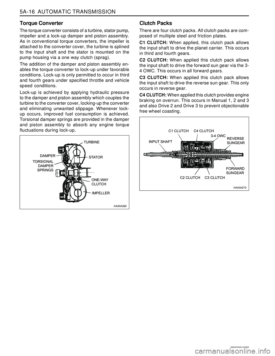
The torque converter consists of a turbine, stator pump,
impeller and a lock-up damper and piston assembly.
As in conventional torque converters, the impeller is
attached to the converter cover, the turbine is splined
to the input shaft and the stator is mounted on the
pump housing via a one way clutch (sprag).
The addition of the damper and piston assembly en-
ables the torque converter to lock-up under favorable
conditions. Lock-up is only permitted to occur in third
and fourth gears under specified throttle and vehicle
speed conditions.
Lock-up is achieved by applying hydraulic pressure
to the damper and piston assembly which couples the
turbine to the converter cover, locking-up the converter
and eliminating unwanted slippage. Whenever lock-
up occurs, improved fuel consumption is achieved.
Torsional damper springs are provided in the damper
and piston assembly to absorb any engine torque
fluctuations during lock-up.
Clutch Packs
There are four clutch packs. All clutch packs are com-
posed of multiple steel and friction plates.
C1 CLUTCH: When applied, this clutch pack allows
the input shaft to drive the planet carrier. This occurs
in third and fourth gears.
C2 CLUTCH: When applied this clutch pack allows
the input shaft to drive the forward sun gear via the 3-
4 OWC. This occurs in all forward gears.
C3 CLUTCH: When applied this clutch pack allows
the input shaft to drive the reverse sun gear. This only
occurs in reverse gear.
C4 CLUTCH: When applied this clutch provides engine
braking on overrun. This occurs in Manual 1, 2 and 3
and also Drive 2 and Drive 3 to prevent objectionable
free wheel coasting.
KAA5A260
KAA5A270
Page 1658 of 2053
BODY WIRING SYSTEM 9A-7
SSANGYONG MY2002
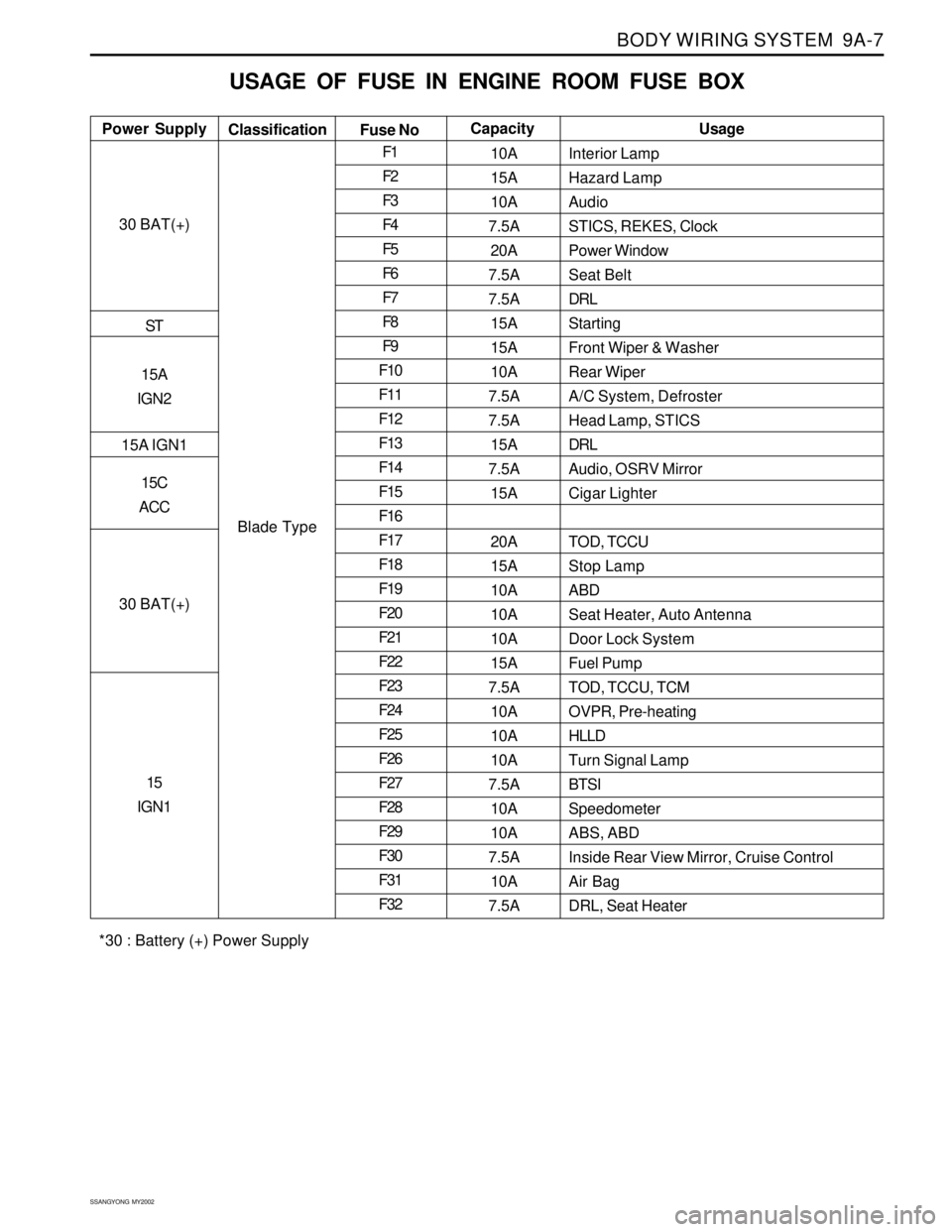
USAGE OF FUSE IN ENGINE ROOM FUSE BOX
Interior Lamp
Hazard Lamp
Audio
STICS, REKES, Clock
Power Window
Seat Belt
DRL
Starting
Front Wiper & Washer
Rear Wiper
A/C System, Defroster
Head Lamp, STICS
DRL
Audio, OSRV Mirror
Cigar Lighter
TOD, TCCU
Stop Lamp
ABD
Seat Heater, Auto Antenna
Door Lock System
Fuel Pump
TOD, TCCU, TCM
OVPR, Pre-heating
HLLD
Turn Signal Lamp
BTSI
Speedometer
ABS, ABD
Inside Rear View Mirror, Cruise Control
Air Bag
DRL, Seat Heater Power SupplyUsage
Classification
Fuse NoCapacity
30 BAT(+)
ST
15A
IGN2
15A IGN1
15C
ACC
30 BAT(+)
15
IGN1
Blade TypeF1
F2
F3
F4
F5
F6
F7
F8
F9
F10
F11
F12
F13
F14
F15
F16
F17
F18
F19
F20
F21
F22
F23
F24
F25
F26
F27
F28
F29
F30
F31
F3210A
15A
10A
7.5A
20A
7.5A
7.5A
15A
15A
10A
7.5A
7.5A
15A
7.5A
15A
20A
15A
10A
10A
10A
15A
7.5A
10A
10A
10A
7.5A
10A
10A
7.5A
10A
7.5A
*30 : Battery (+) Power Supply
Page 1868 of 2053
2-4 2-4 2-4 2-4
2-4
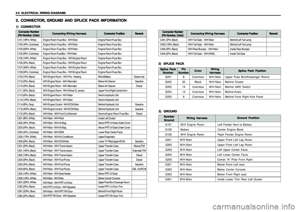
ELECTRICAL WIRING DIAGRAMS ELECTRICAL WIRING DIAGRAMSELECTRICAL WIRING DIAGRAMS ELECTRICAL WIRING DIAGRAMS
ELECTRICAL WIRING DIAGRAMS
Engine Room Fuse Box - W/H Main
Engine Room Fuse Box - W/H Main
Engine Room Fuse Box - W/H Main
Engine Room FuseBox - W/H Main
Engine Room Fuse Box - W/H Engine Room
Engine Room Fuse Box - W/H Engine Room
Engine Room Fuse Box - W/H Engine Room
Engine Room Fuse Box - W/H Engine Room
W/H Engine Room - W/H Pre - Heating
W/H Engine Room - W/H Alternator
W/H Engine Room - W/H Alternator
W/H Engine Room - W/H Wheel G. sensor
W/H Engine Room - W/H Main
W/H Engine Room - W/H Main
W/H Engine Control - W/H ECM Main
W/H Engine Control - W/H ECM Main
W/H Main - W/H Fuel Cut Solenoid
W/H Main - W/H Roof
W/H Main - W/H Air Bag
W/H Main - W/H Air Bag
W/H Main - W/H SDM
W/H Main - W/H Air Conditioner
W/H Main - W/H ECM Main
W/H Main - W/H Transmission
W/H Main - W/H Transmission
W/H Main - W/H Transmission
W/H Main - W/H Fuel Pump
W/H Main - W/H Fuel Pump
W/H Main - W/H Fuel Pump
W/H Main - W/H Seat Heater
W/H Main - W/H Main
W/H Main - W/H FRT LH Door
W/H FRT LH Door - W/H Speaker
W/H Main - W/H FRT RH Door
W/H FRT RH Door - W/H Speaker
G201W/H Main Upper Front Left Leg Room
G202W/H Main Upper Front Left Leg Room
G203W/H Main Left Upper Center Facia
G204W/H Main Left Lower Center Facia
G205W/H Main Center "A" Pillar Front Right
G301W/H Main Below Front Left seat
G302W/H Main Below Center Console
G303W/H Main Below Front Right seat
G401W/H Main Inside Lower Trim Rear Left Quater
Engine Room Fuse Box
Engine Room Fuse Box
Engine Room Fuse Box
Engine Room Fuse Box
Engine Room Fuse Box
Engine Room Fuse Box
Engine Room Fuse Box
Engine Room Fuse Box
Bhind Battery
Below Air Cleaner
Below Air Cleaner
Upper Front Right Control Arm
Next to Hydraulic Unit
Next to Hydraulic Unit
Behind Hydraulic Unit
Behind Hydraulic Unit
Next to Engine Room Fuse Box
Inside Left Cluster
Above FRT LH Seat Under Cover
Above FRT LH Seat Under Cover
Lower Rear Center Facia
Upper Evaporator
Lower "A" Piller(Upper ECM)
Upper Transfer Case
Upper Transfer Case
Upper Transfer Case
Upper Transfer Case
Upper Transfer Case
Upper Transfer Case
Below FRT LH Seat
Below Center Console
Upper Fuse Box
(Passenger Room)
Inside FRT LH Door Trim
Behind Front Right Panel
Inside FRT RH Door Trim
2. 2.2. 2.
2.
CONNECT CONNECTCONNECT CONNECT
CONNECT
OR, OR,OR, OR,
OR,
GR GR GR GR
GR
OUND AND SPLICE PA OUND AND SPLICE PAOUND AND SPLICE PA OUND AND SPLICE PA
OUND AND SPLICE PA
CK INFORMA CK INFORMACK INFORMA CK INFORMA
CK INFORMA
TION TIONTION TION
TION1) 1)1) 1)
1)
CONNECTOR CONNECTORCONNECTOR CONNECTOR
CONNECTORConnector Number Connector NumberConnector Number Connector Number
Connector Number
(Pin Number, Color) (Pin Number, Color)(Pin Number, Color) (Pin Number, Color)
(Pin Number, Color)Connecting Connecting Connecting Connecting
Connecting
Wiring Harness Wiring HarnessWiring Harness Wiring Harness
Wiring Harness
Connector Position Connector PositionConnector Position Connector Position
Connector Position
C101 (19Pin, White)
C102 (4Pin, Colorless)
C103 (22Pin, White)
C104 (8Pin, Colorless)
C105 (10Pin, White)
C106 (3Pin, Black)
C107 (20Pin, White)
C108 (6Pin, Colorless)
C109 (1Pin, Black)
C110 (2Pin, Black)
C110 (4Pin, Black)
C111 (3Pin, Black)
C112 (6Pin, Black)
C113 (12Pin, Black)
C114 (6Pin, Gray)
C115 (40Pin, Black)
C116 (3Pin, Black)
C201 (8Pin, White)
C202 (4Pin, White)
C203 (2Pin, Black)
C204 (4Pin, Colorless)
C205 (17Pin, White)
C206 (6Pin, Black)
C301 (2Pin, Black)
C301 (16Pin, Black)
C302 (10Pin, Black)
C303 (3Pin, Black)
C303 (4Pin, Black)
C303 (6Pin, Black)
C304 (10Pin, White)
C305 (14Pin, White)
C351 (22Pin, White)
C352 (2Pin, Black)
C361 (22Pin, Blue)
C362 (2Pin, Black)
2) 2)2) 2)
2)
SPLICE PACK SPLICE PACKSPLICE PACK SPLICE PACK
SPLICE PACK
S201
S202
S203
S204
S205Splice Pack Position Splice Pack PositionSplice Pack Position Splice Pack Position
Splice Pack Position Wiring WiringWiring Wiring
Wiring
Harness HarnessHarness Harness
Harness Color ColorColor Color
Color Splice Pack Splice PackSplice Pack Splice Pack
Splice Pack
Number NumberNumber Number
Number
Colorless
Black
Colorless
Colorless
ColorlessW/H Main
W/H Main
W/H Main
W/H Main
W/H MainUpper Fuse Box(Passenger Room)
Behind Cluster
Behind 4WD Switch
Behind Audio
Behind Front Right Kick Panel
Remark RemarkRemark Remark
Remark
Diesel only
Gasoline
Diesel
Gasoline
Gasoline
Diesel
Gasoline
Manual T/M
Automatic T/M
Diesel
Diesel
Gasoline
GSL : EURO IIIBehind Left Tail Lamp
Behind Left Tail Lamp
Inside Rear Bumper
Inside Tail Gate
Connector Number Connector NumberConnector Number Connector Number
Connector Number
(Pin Number, Color) (Pin Number, Color)(Pin Number, Color) (Pin Number, Color)
(Pin Number, Color)Connecting Connecting Connecting Connecting
Connecting
Wiring Harness Wiring HarnessWiring Harness Wiring Harness
Wiring Harness
Connector Position Connector PositionConnector Position Connector Position
Connector Position
C401 (2Pin, Black)
C402 (12Pin, Black)
C403 (3Pin, Black)
C404 (2Pin, Black)W/H Tail Gate - W/H Main
W/H Tail Gate - W/H Main
W/H Rear Bumper - W/H Main
W/H Tail Gate - W/H HMSL
Remark RemarkRemark Remark
Remark
3) 3)3) 3)
3)
GROUND GROUNDGROUND GROUND
GROUND
G101
G102
G103Ground Position Ground PositionGround Position Ground Position
Ground Position
Wiring Harness Wiring HarnessWiring Harness Wiring Harness
Wiring Harness Number NumberNumber Number
Number
Ground GroundGround Ground
Ground
W/H Engine Room
Battery
W/H Engine RoomLeft Fender Next to Battery
Center Engine Block
Right Fender Engine Room
Pin PinPin Pin
Pin
Number NumberNumber Number
Number
8
20
14
14
8
Page 1893 of 2053
USAGE AND CAPACITY OF FUSES IN FUSE BOX USAGE AND CAPACITY OF FUSES IN FUSE BOX USAGE AND CAPACITY OF FUSES IN FUSE BOX USAGE AND CAPACITY OF FUSES IN FUSE BOX
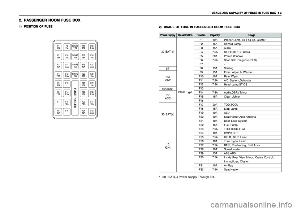
USAGE AND CAPACITY OF FUSES IN FUSE BOX
4-3 4-34-3 4-3
4-3
2. 2.2. 2.
2.
PASSENGER ROOM FUSE BOX PASSENGER ROOM FUSE BOXPASSENGER ROOM FUSE BOX PASSENGER ROOM FUSE BOX
PASSENGER ROOM FUSE BOX1) 1)1) 1)
1)
POSITION OF FUSE POSITION OF FUSEPOSITION OF FUSE POSITION OF FUSE
POSITION OF FUSE
2) 2)2) 2)
2)
USAGE OF FUSE IN PASSENGER ROOM FUSE BOX USAGE OF FUSE IN PASSENGER ROOM FUSE BOXUSAGE OF FUSE IN PASSENGER ROOM FUSE BOX USAGE OF FUSE IN PASSENGER ROOM FUSE BOX
USAGE OF FUSE IN PASSENGER ROOM FUSE BOX
10A
15A
15A
7.5A
30A
7.5A
-
15A
15A
10A
7.5A
7.5A
-
7.5A
15A
20A
15A
10A
10A
10A
15A
7.5A
10A
7.5A
10A
7.5A
10A
15A
7.5A
10A
7.5A F1
F2
F3
F4
F5
F6
F7
F8
F9
F10
F11
F12
F13
F14
F15
F16
F17
F18
F19
F20
F21
F22
F23
F24
F25
F26
F27
F28
F29
F30
F31
F32
Power Supply Power SupplyPower Supply Power Supply
Power Supply
Classification ClassificationClassification Classification
Classification
Fuse No Fuse NoFuse No Fuse No
Fuse No
Capacity CapacityCapacity Capacity
Capacity
Usage UsageUsage Usage
Usage* 30 : BAT(+) Power Supply Through Ef1.
Blade TypeInterior Lamp, Rr Fog Lp, Cluster
Hazard Lamp
Audio
STICS,REKES,Clock
Power Window
Seat Belt, Diagnosis(DLC)
-
Starting
Front Wiper & Washer
Rear Wiper
A/C System,Defroster
Head Lamp,STICS
-
Audio,OSRV Mirror
Cigar Lighter
TOD,TCCU
Stop Lamp
ABD
Seat Heater,Auto Antenna
Door Lock System
Fuel Pump
TOD,TCCU,TCM
OVPR,EGR
HLLD, B/UP Lamp
Turn Signal Lamp
BTSI, Pre-heating, Shift Lock
Speedometer
ABS,ABD
Inside Rear View Mirror, Cruise Control,
Immobilizer, Cluster
Air Bag
Seat Heater
30 BAT(+)
ST
15A
IGN2
30 BAT(+)15C
ACC 15A IGN1
15
IGN1
Page 1894 of 2053
4-4 4-4 4-4 4-4
4-4
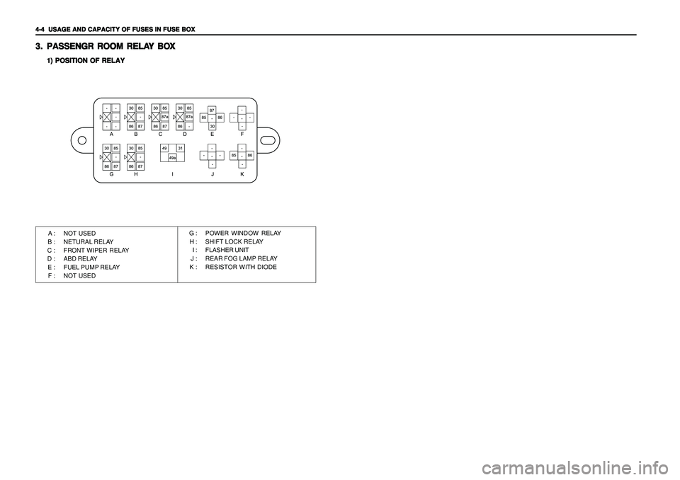
USAGE AND CAPACITY OF FUSES IN FUSE BOX USAGE AND CAPACITY OF FUSES IN FUSE BOXUSAGE AND CAPACITY OF FUSES IN FUSE BOX USAGE AND CAPACITY OF FUSES IN FUSE BOX
USAGE AND CAPACITY OF FUSES IN FUSE BOX3. 3.3. 3.
3.
PASSENGR R PASSENGR RPASSENGR R PASSENGR R
PASSENGR R
OOM RELA OOM RELAOOM RELA OOM RELA
OOM RELA
Y BO Y BOY BO Y BO
Y BO
X XX X
X
1) POSITION OF RELAY 1) POSITION OF RELAY1) POSITION OF RELAY 1) POSITION OF RELAY
1) POSITION OF RELAYA : NOT USED
B : NETURAL RELAY
C : FRONT WIPER RELAY
D : ABD RELAY
E : FUEL PUMP RELAY
F : NOT USEDG : POWER WINDOW RELAY
H : SHIFT LOCK RELAY
I : FLASHER UNIT
J : REAR FOG LAMP RELAY
K : RESISTOR WITH DIODE