1997 SSANGYONG KORANDO wheel alignment
[x] Cancel search: wheel alignmentPage 1312 of 2053
SSANGYONG MY2002
5B-4 MANUAL TRANSMISSION
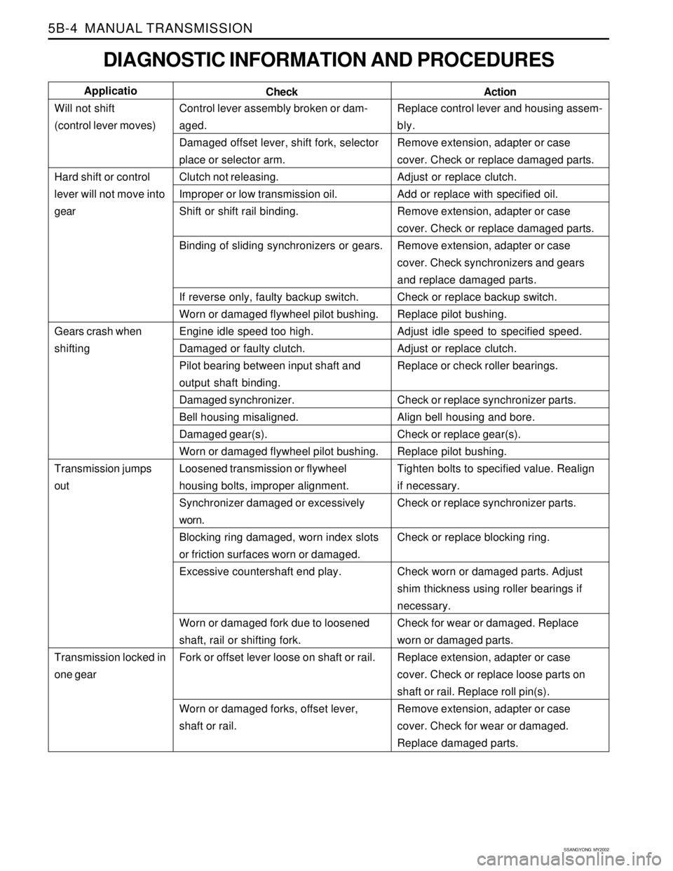
DIAGNOSTIC INFORMATION AND PROCEDURES
Control lever assembly broken or dam-
aged.
Damaged offset lever, shift fork, selector
place or selector arm.
Clutch not releasing.
Improper or low transmission oil.
Shift or shift rail binding.
Binding of sliding synchronizers or gears.
If reverse only, faulty backup switch.
Worn or damaged flywheel pilot bushing.
Engine idle speed too high.
Damaged or faulty clutch.
Pilot bearing between input shaft and
output shaft binding.
Damaged synchronizer.
Bell housing misaligned.
Damaged gear(s).
Worn or damaged flywheel pilot bushing.
Loosened transmission or flywheel
housing bolts, improper alignment.
Synchronizer damaged or excessively
worn.
Blocking ring damaged, worn index slots
or friction surfaces worn or damaged.
Excessive countershaft end play.
Worn or damaged fork due to loosened
shaft, rail or shifting fork.
Fork or offset lever loose on shaft or rail.
Worn or damaged forks, offset lever,
shaft or rail.Replace control lever and housing assem-
bly.
Remove extension, adapter or case
cover. Check or replace damaged parts.
Adjust or replace clutch.
Add or replace with specified oil.
Remove extension, adapter or case
cover. Check or replace damaged parts.
Remove extension, adapter or case
cover. Check synchronizers and gears
and replace damaged parts.
Check or replace backup switch.
Replace pilot bushing.
Adjust idle speed to specified speed.
Adjust or replace clutch.
Replace or check roller bearings.
Check or replace synchronizer parts.
Align bell housing and bore.
Check or replace gear(s).
Replace pilot bushing.
Tighten bolts to specified value. Realign
if necessary.
Check or replace synchronizer parts.
Check or replace blocking ring.
Check worn or damaged parts. Adjust
shim thickness using roller bearings if
necessary.
Check for wear or damaged. Replace
worn or damaged parts.
Replace extension, adapter or case
cover. Check or replace loose parts on
shaft or rail. Replace roll pin(s).
Remove extension, adapter or case
cover. Check for wear or damaged.
Replace damaged parts. Check Applicatio
Will not shift
(control lever moves)
Hard shift or control
lever will not move into
gear
Gears crash when
shifting
Transmission jumps
out
Transmission locked in
one gear
Action
Page 1313 of 2053
MANUAL TRANSMISSION 5B-5
SSANGYONG MY2002
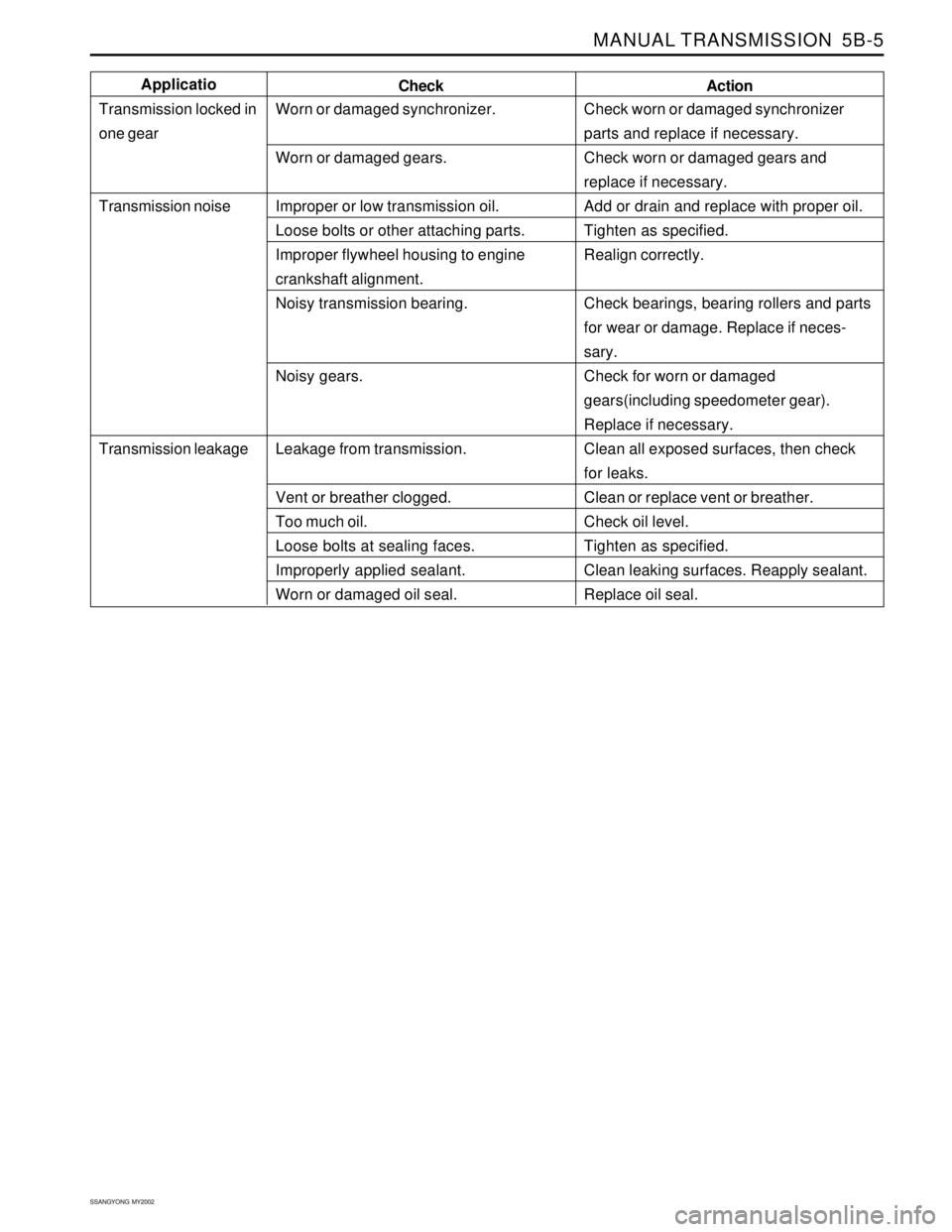
Check worn or damaged synchronizer
parts and replace if necessary.
Check worn or damaged gears and
replace if necessary.
Add or drain and replace with proper oil.
Tighten as specified.
Realign correctly.
Check bearings, bearing rollers and parts
for wear or damage. Replace if neces-
sary.
Check for worn or damaged
gears(including speedometer gear).
Replace if necessary.
Clean all exposed surfaces, then check
for leaks.
Clean or replace vent or breather.
Check oil level.
Tighten as specified.
Clean leaking surfaces. Reapply sealant.
Replace oil seal.
Action
Worn or damaged synchronizer.
Worn or damaged gears.
Improper or low transmission oil.
Loose bolts or other attaching parts.
Improper flywheel housing to engine
crankshaft alignment.
Noisy transmission bearing.
Noisy gears.
Leakage from transmission.
Vent or breather clogged.
Too much oil.
Loose bolts at sealing faces.
Improperly applied sealant.
Worn or damaged oil seal.Check Applicatio
Transmission locked in
one gear
Transmission noise
Transmission leakage
Page 1330 of 2053
SSANGYONG MY2002
5B-22 MANUAL TRANSMISSION
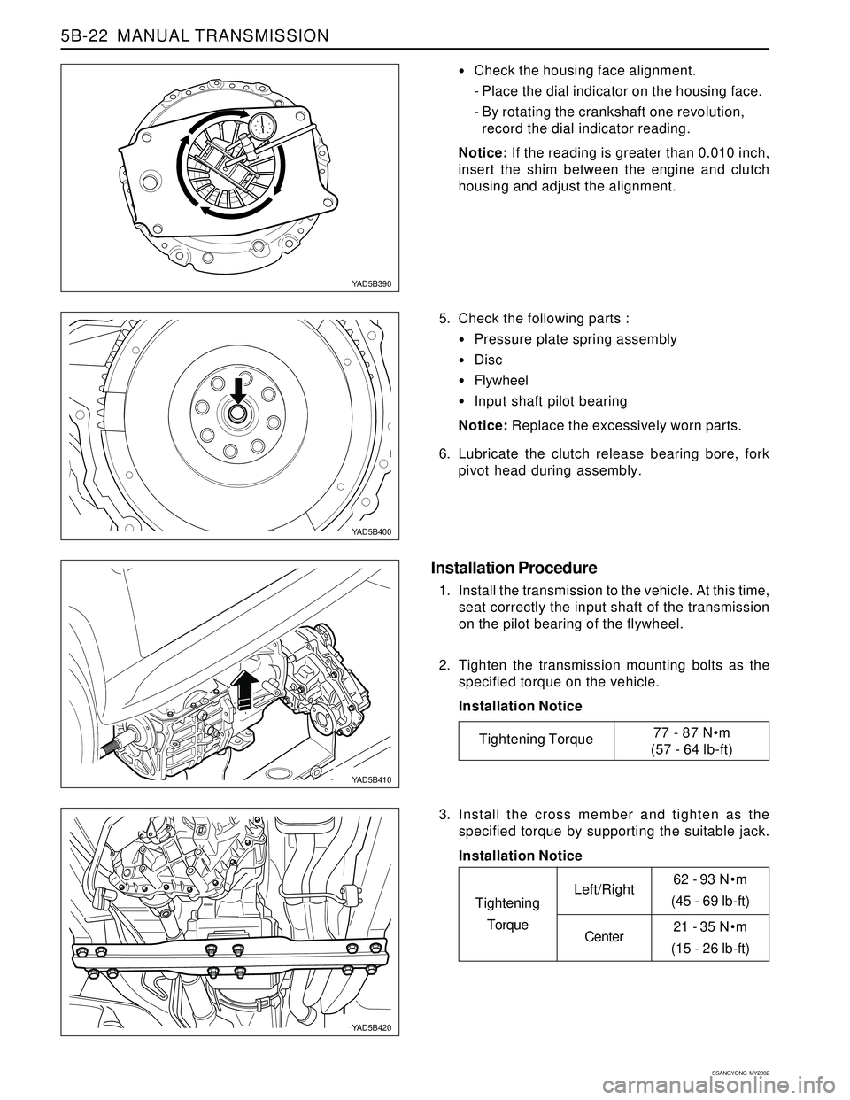
62 - 93 Nm
(45 - 69 lb-ft)
21 - 35 Nm
(15 - 26 lb-ft)
Check the housing face alignment.
- Place the dial indicator on the housing face.
- By rotating the crankshaft one revolution,
record the dial indicator reading.
Notice: If the reading is greater than 0.010 inch,
insert the shim between the engine and clutch
housing and adjust the alignment.
5. Check the following parts :
Pressure plate spring assembly
Disc
Flywheel
Input shaft pilot bearing
Notice: Replace the excessively worn parts.
6. Lubricate the clutch release bearing bore, fork
pivot head during assembly.
Installation Procedure
1. Install the transmission to the vehicle. At this time,
seat correctly the input shaft of the transmission
on the pilot bearing of the flywheel.
2. Tighten the transmission mounting bolts as the
specified torque on the vehicle.
Installation Notice
YAD5B390
YAD5B400
YAD5B410
YAD5B420
Tightening Torque77 - 87 Nm
(57 - 64 lb-ft)
3. Install the cross member and tighten as the
specified torque by supporting the suitable jack.
Installation Notice
Tightening
TorqueLeft/Right
Center
Page 1472 of 2053
SSANGYONG MY2002
6C-4 POWER STEERING GEAR
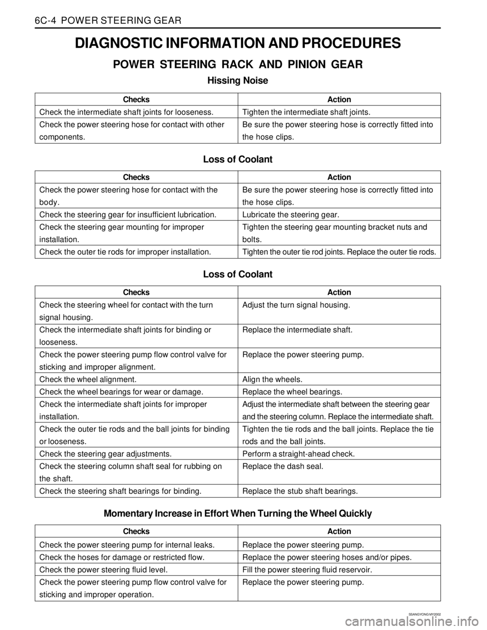
DIAGNOSTIC INFORMATION AND PROCEDURES
POWER STEERING RACK AND PINION GEAR
Hissing Noise
Check the intermediate shaft joints for looseness.
Check the power steering hose for contact with other
components.ChecksActionTighten the intermediate shaft joints.
Be sure the power steering hose is correctly fitted into
the hose clips.
Loss of Coolant
Check the power steering hose for contact with the
body.
Check the steering gear for insufficient lubrication.
Check the steering gear mounting for improper
installation.
Check the outer tie rods for improper installation.ChecksActionBe sure the power steering hose is correctly fitted into
the hose clips.
Lubricate the steering gear.
Tighten the steering gear mounting bracket nuts and
bolts.
Tighten the outer tie rod joints. Replace the outer tie rods.
Loss of Coolant
Check the steering wheel for contact with the turn
signal housing.
Check the intermediate shaft joints for binding or
looseness.
Check the power steering pump flow control valve for
sticking and improper alignment.
Check the wheel alignment.
Check the wheel bearings for wear or damage.
Check the intermediate shaft joints for improper
installation.
Check the outer tie rods and the ball joints for binding
or looseness.
Check the steering gear adjustments.
Check the steering column shaft seal for rubbing on
the shaft.
Check the steering shaft bearings for binding.ChecksActionAdjust the turn signal housing.
Replace the intermediate shaft.
Replace the power steering pump.
Align the wheels.
Replace the wheel bearings.
Adjust the intermediate shaft between the steering gear
and the steering column. Replace the intermediate shaft.
Tighten the tie rods and the ball joints. Replace the tie
rods and the ball joints.
Perform a straight-ahead check.
Replace the dash seal.
Replace the stub shaft bearings.
Check the power steering pump for internal leaks.
Check the hoses for damage or restricted flow.
Check the power steering fluid level.
Check the power steering pump flow control valve for
sticking and improper operation.ChecksActionReplace the power steering pump.
Replace the power steering hoses and/or pipes.
Fill the power steering fluid reservoir.
Replace the power steering pump.
Momentary Increase in Effort When Turning the Wheel Quickly
Page 1478 of 2053
SSANGYONG MY2002
6C-10 POWER STEERING GEAR
KAA6C090
KAA6C100
KAA6C110
KAA6C080
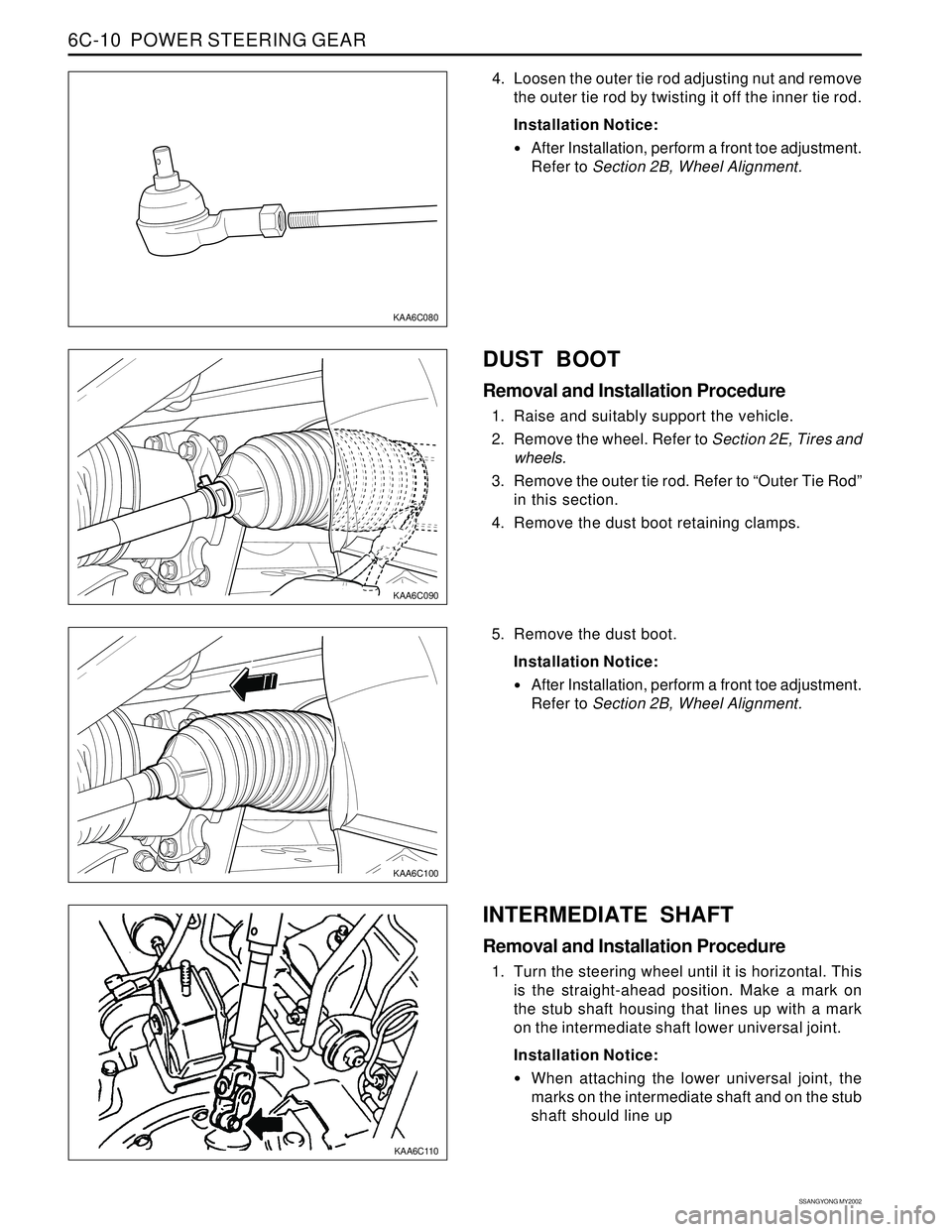
4. Loosen the outer tie rod adjusting nut and remove
the outer tie rod by twisting it off the inner tie rod.
Installation Notice:
After Installation, perform a front toe adjustment.
Refer to Section 2B, Wheel Alignment.
DUST BOOT
Removal and Installation Procedure
1. Raise and suitably support the vehicle.
2. Remove the wheel. Refer to Section 2E, Tires and
wheels.
3. Remove the outer tie rod. Refer to “Outer Tie Rod”
in this section.
4. Remove the dust boot retaining clamps.
5. Remove the dust boot.
Installation Notice:
After Installation, perform a front toe adjustment.
Refer to Section 2B, Wheel Alignment.
INTERMEDIATE SHAFT
Removal and Installation Procedure
1. Turn the steering wheel until it is horizontal. This
is the straight-ahead position. Make a mark on
the stub shaft housing that lines up with a mark
on the intermediate shaft lower universal joint.
Installation Notice:
When attaching the lower universal joint, the
marks on the intermediate shaft and on the stub
shaft should line up
Page 1481 of 2053
POWER STEERING GEAR 6C-13
SSANGYONG MY2002
KAA6C150
UNIT REPAIR
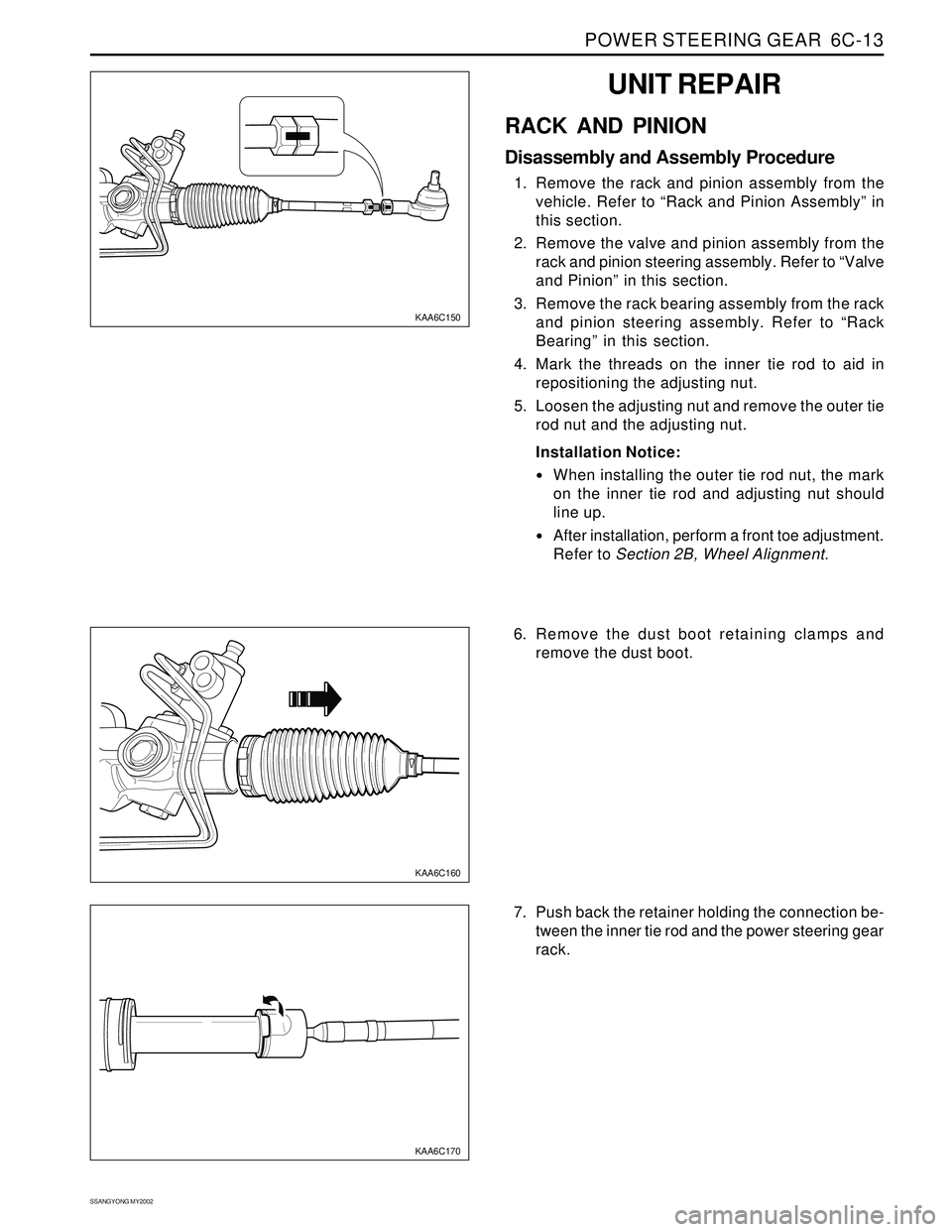
RACK AND PINION
Disassembly and Assembly Procedure
1. Remove the rack and pinion assembly from the
vehicle. Refer to “Rack and Pinion Assembly” in
this section.
2. Remove the valve and pinion assembly from the
rack and pinion steering assembly. Refer to “Valve
and Pinion” in this section.
3. Remove the rack bearing assembly from the rack
and pinion steering assembly. Refer to “Rack
Bearing” in this section.
4. Mark the threads on the inner tie rod to aid in
repositioning the adjusting nut.
5. Loosen the adjusting nut and remove the outer tie
rod nut and the adjusting nut.
Installation Notice:
When installing the outer tie rod nut, the mark
on the inner tie rod and adjusting nut should
line up.
After installation, perform a front toe adjustment.
Refer to Section 2B, Wheel Alignment.
KAA6C160
KAA6C170
6. Remove the dust boot retaining clamps and
remove the dust boot.
7. Push back the retainer holding the connection be-
tween the inner tie rod and the power steering gear
rack.
Page 1643 of 2053
SUPPLEMENTAL RESTRAINTS SYSTEM 8B-61
SSANGYONG MY2002
KAA8B050
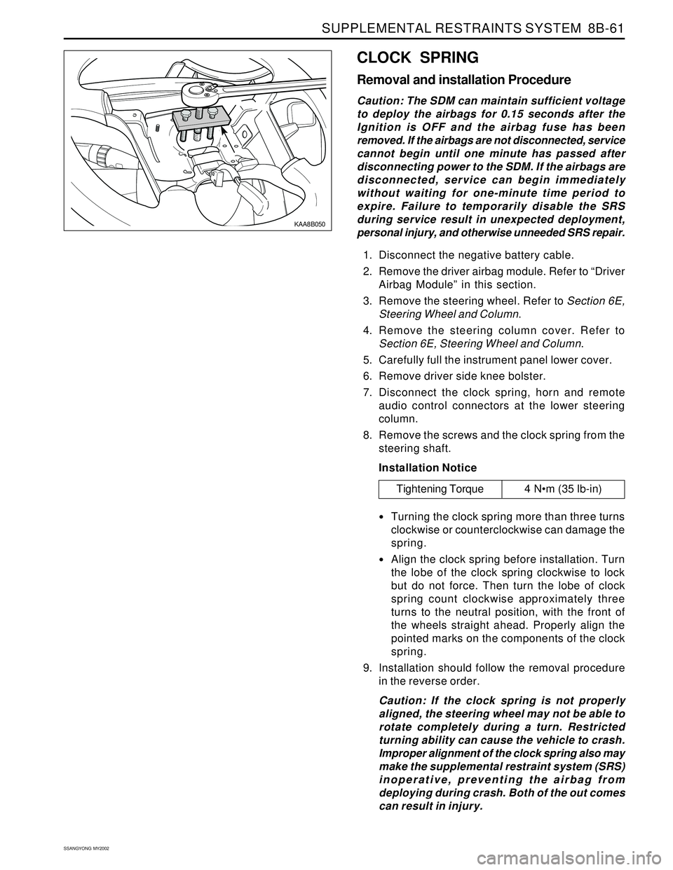
CLOCK SPRING
Removal and installation Procedure
Caution: The SDM can maintain sufficient voltage
to deploy the airbags for 0.15 seconds after the
Ignition is OFF and the airbag fuse has been
removed. If the airbags are not disconnected, service
cannot begin until one minute has passed after
disconnecting power to the SDM. If the airbags are
disconnected, service can begin immediately
without waiting for one-minute time period to
expire. Failure to temporarily disable the SRS
during service result in unexpected deployment,
personal injury, and otherwise unneeded SRS repair.
1. Disconnect the negative battery cable.
2. Remove the driver airbag module. Refer to “Driver
Airbag Module” in this section.
3. Remove the steering wheel. Refer to Section 6E,
Steering Wheel and Column.
4. Remove the steering column cover. Refer to
Section 6E, Steering Wheel and Column.
5. Carefully full the instrument panel lower cover.
6. Remove driver side knee bolster.
7. Disconnect the clock spring, horn and remote
audio control connectors at the lower steering
column.
8. Remove the screws and the clock spring from the
steering shaft.
Installation Notice
Turning the clock spring more than three turns
clockwise or counterclockwise can damage the
spring.
Align the clock spring before installation. Turn
the lobe of the clock spring clockwise to lock
but do not force. Then turn the lobe of clock
spring count clockwise approximately three
turns to the neutral position, with the front of
the wheels straight ahead. Properly align the
pointed marks on the components of the clock
spring.
9. Installation should follow the removal procedure
in the reverse order.
Caution: If the clock spring is not properly
aligned, the steering wheel may not be able to
rotate completely during a turn. Restricted
turning ability can cause the vehicle to crash.
Improper alignment of the clock spring also may
make the supplemental restraint system (SRS)
inoperative, preventing the airbag from
deploying during crash. Both of the out comes
can result in injury.
Tightening Torque 4 Nm (35 lb-in)