1997 SSANGYONG KORANDO heating
[x] Cancel search: heatingPage 1508 of 2053
HEATING AND VENTILATION SYSTEM 7A-7
SSANGYONG MY2002
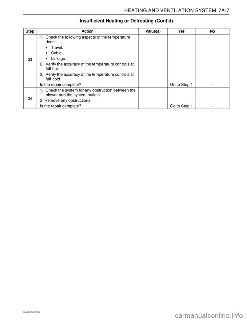
Insufficient Heating or Defrosting (Cont’d)
Step
33
34Action
1. Check the following aspects of the temperature
door:
Travel.
Cable.
Linkage.
2. Verify the accuracy of the temperature controls at
full hot.
3. Verify the accuracy of the temperature controls at
full cold.
Is the repair complete?
1. Check the system for any obstruction between the
blower and the system outlets.
2. Remove any obstructions.
Is the repair complete?Yes
Go to Step 1
Go to Step 1No
-
- Value(s)
Page 1509 of 2053
SSANGYONG MY2002
7A-8 HEATING AND VENTILATION SYSTEM
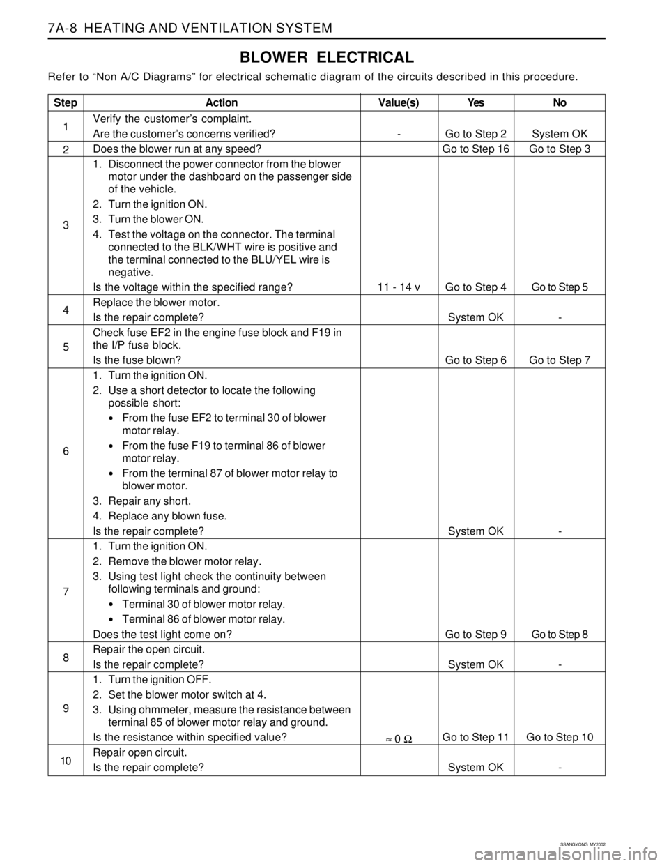
BLOWER ELECTRICAL
Refer to “Non A/C Diagrams” for electrical schematic diagram of the circuits described in this procedure.
Step
1
2
3
4
5
6
7
8
9
10
Action
Verify the customer’s complaint.
Are the customer’s concerns verified?
Does the blower run at any speed?
1. Disconnect the power connector from the blower
motor under the dashboard on the passenger side
of the vehicle.
2. Turn the ignition ON.
3. Turn the blower ON.
4. Test the voltage on the connector. The terminal
connected to the BLK/WHT wire is positive and
the terminal connected to the BLU/YEL wire is
negative.
Is the voltage within the specified range?
Replace the blower motor.
Is the repair complete?
Check fuse EF2 in the engine fuse block and F19 in
the I/P fuse block.
Is the fuse blown?
1. Turn the ignition ON.
2. Use a short detector to locate the following
possible short:
From the fuse EF2 to terminal 30 of blower
motor relay.
From the fuse F19 to terminal 86 of blower
motor relay.
From the terminal 87 of blower motor relay to
blower motor.
3. Repair any short.
4. Replace any blown fuse.
Is the repair complete?
1. Turn the ignition ON.
2. Remove the blower motor relay.
3. Using test light check the continuity between
following terminals and ground:
Terminal 30 of blower motor relay.
Terminal 86 of blower motor relay.
Does the test light come on?
Repair the open circuit.
Is the repair complete?
1. Turn the ignition OFF.
2. Set the blower motor switch at 4.
3. Using ohmmeter, measure the resistance between
terminal 85 of blower motor relay and ground.
Is the resistance within specified value?
Repair open circuit.
Is the repair complete?Yes
Go to Step 2
Go to Step 16
Go to Step 4
System OK
Go to Step 6
System OK
Go to Step 9
System OK
Go to Step 11
System OKNo
System OK
Go to Step 3
Go to Step 5
-
Go to Step 7
-
Go to Step 8
-
Go to Step 10
-
Value(s)
-
11 - 14 v
≈ 0 Ω
Page 1510 of 2053
HEATING AND VENTILATION SYSTEM 7A-9
SSANGYONG MY2002
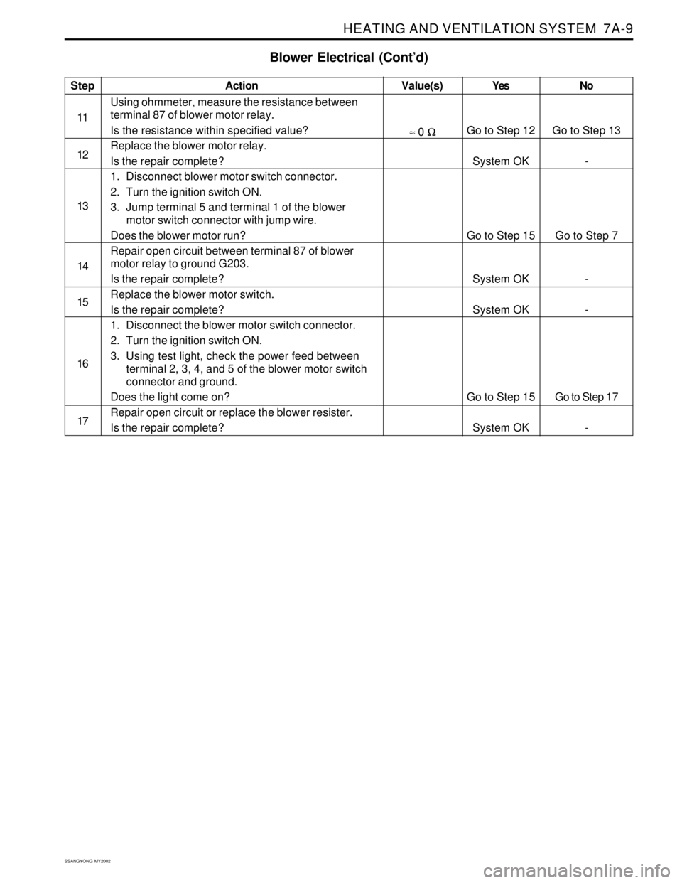
Blower Electrical (Cont’d)
Step
11
12
13
14
15
16
17Action
Using ohmmeter, measure the resistance between
terminal 87 of blower motor relay.
Is the resistance within specified value?
Replace the blower motor relay.
Is the repair complete?
1. Disconnect blower motor switch connector.
2. Turn the ignition switch ON.
3. Jump terminal 5 and terminal 1 of the blower
motor switch connector with jump wire.
Does the blower motor run?
Repair open circuit between terminal 87 of blower
motor relay to ground G203.
Is the repair complete?
Replace the blower motor switch.
Is the repair complete?
1. Disconnect the blower motor switch connector.
2. Turn the ignition switch ON.
3. Using test light, check the power feed between
terminal 2, 3, 4, and 5 of the blower motor switch
connector and ground.
Does the light come on?
Repair open circuit or replace the blower resister.
Is the repair complete?Yes
Go to Step 12
System OK
Go to Step 15
System OK
System OK
Go to Step 15
System OKNo
Go to Step 13
-
Go to Step 7
-
-
Go to Step 17
-Value(s)
≈ 0 Ω
Page 1511 of 2053
SSANGYONG MY2002
7A-10 HEATING AND VENTILATION SYSTEM
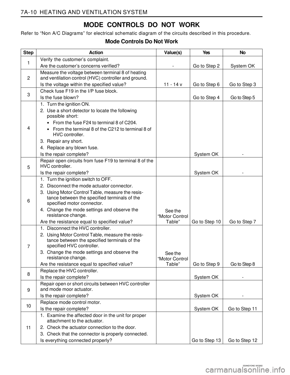
MODE CONTROLS DO NOT WORK
Refer to “Non A/C Diagrams” for electrical schematic diagram of the circuits described in this procedure.
Mode Controls Do Not Work
Step
1
2
3
4
5
6
7
8
9
10
11Action
Verify the customer’s complaint.
Are the customer’s concerns verified?
Measure the voltage between terminal 8 of heating
and ventilation control (HVC) controller and ground.
Is the voltage within the specified value?
Check fuse F19 in the I/P fuse block.
Is the fuse blown?
1. Turn the ignition ON.
2. Use a short detector to locate the following
possible short:
From the fuse F24 to terminal 8 of C204.
From the terminal 8 of the C212 to terminal 8 of
HVC controller.
3. Repair any short.
4. Replace any blown fuse.
Is the repair complete?
Repair open circuits from fuse F19 to terminal 8 of the
HVC controller.
Is the repair complete?
1. Turn the ignition switch to OFF.
2. Disconnect the mode actuator connector.
3. Using Motor Control Table, measure the resis-
tance between the specified terminals of the
specified motor connector.
4. Change the mode settings and observe the
resistance change.
Are the resistance equal to specified value?
1. Disconnect the HVC controller.
2. Using Motor Control Table, measure the resis-
tance between the specified terminals of the
specified HVC controller.
3. Change the mode settings and observe the
resistance change.
Are the resistance equal to specified value?
Replace the HVC controller.
Is the repair complete?
Repair open or short circuits between HVC controller
and mode moor actuator.
Is the repair complete?
Replace mode control motor.
Is the repair complete?
1. Examine the affected door in the unit for proper
attachment to the actuator.
2. Check the actuator connection to the door.
3. Check that the connector is properly connected.
Is everything connected properly?Yes
Go to Step 2
Go to Step 6
Go to Step 4
System OK
System OK
Go to Step 10
Go to Step 9
System OK
System OK
System OK
Go to Step 13No
System OK
Go to Step 3
Go to Step 5
-
-
Go to Step 7
Go to Step 8
-
-
Go to Step 11
Go to Step 12
Value(s)
-
11 - 14 v
See the
“Motor Control
Table”
See the
“Motor Control
Table”
Page 1512 of 2053
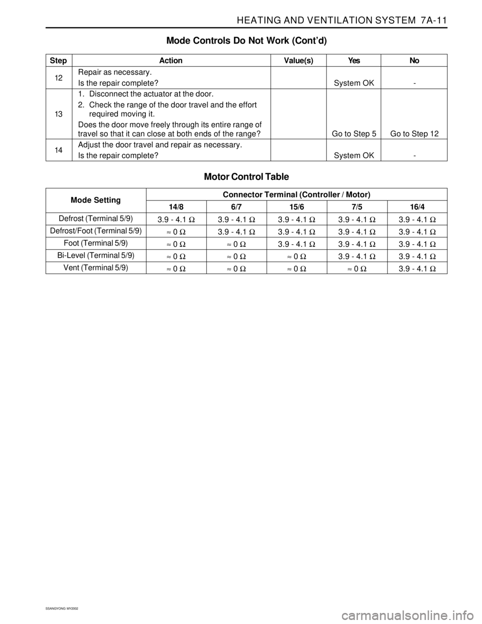
HEATING AND VENTILATION SYSTEM 7A-11
SSANGYONG MY2002
Defrost (Terminal 5/9)
Defrost/Foot (Terminal 5/9)
Foot (Terminal 5/9)
Bi-Level (Terminal 5/9)
Vent (Terminal 5/9)
Mode Controls Do Not Work (Cont’d)
Step
12
13
14Action
Repair as necessary.
Is the repair complete?
1. Disconnect the actuator at the door.
2. Check the range of the door travel and the effort
required moving it.
Does the door move freely through its entire range of
travel so that it can close at both ends of the range?
Adjust the door travel and repair as necessary.
Is the repair complete?Yes
System OK
Go to Step 5
System OKNo
-
Go to Step 12
-Value(s)
6/7
3.9 - 4.1 Ω
3.9 - 4.1 Ω
≈ 0 Ω
≈ 0 Ω
≈ 0 Ω 14/8
3.9 - 4.1 Ω
≈ 0 Ω
≈ 0 Ω
≈ 0 Ω
≈ 0 ΩConnector Terminal (Controller / Motor)
Mode Setting
Motor Control Table
15/6
3.9 - 4.1 Ω
3.9 - 4.1 Ω
3.9 - 4.1 Ω
≈ 0 Ω
≈ 0 Ω7/5
3.9 - 4.1 Ω
3.9 - 4.1 Ω
3.9 - 4.1 Ω
3.9 - 4.1 Ω
≈ 0 Ω16/4
3.9 - 4.1 Ω
3.9 - 4.1 Ω
3.9 - 4.1 Ω
3.9 - 4.1 Ω
3.9 - 4.1 Ω
Page 1513 of 2053
SSANGYONG MY2002
7A-12 HEATING AND VENTILATION SYSTEM
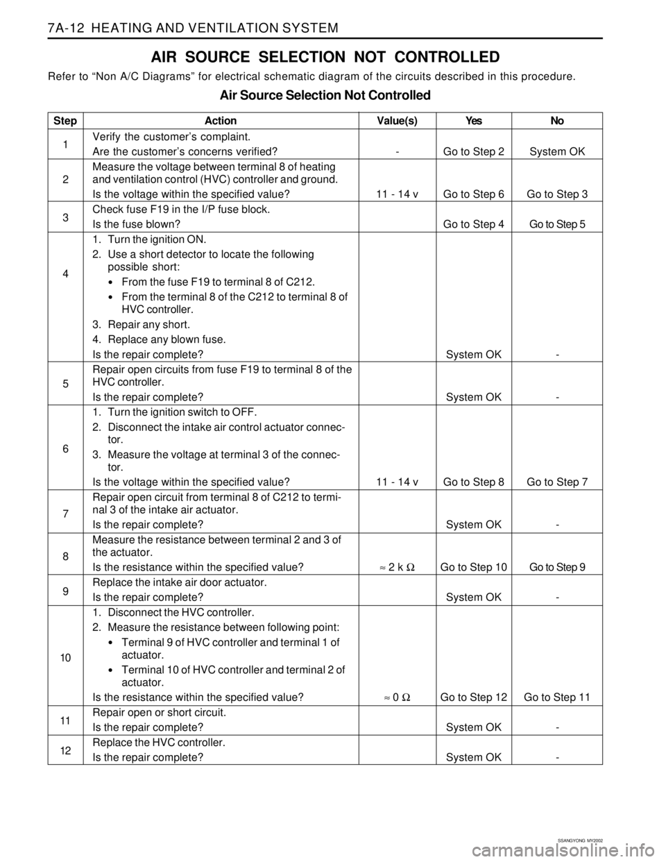
AIR SOURCE SELECTION NOT CONTROLLED
Refer to “Non A/C Diagrams” for electrical schematic diagram of the circuits described in this procedure.
Air Source Selection Not Controlled
Step
1
2
3
4
5
6
7
8
9
10
11
12Action
Verify the customer’s complaint.
Are the customer’s concerns verified?
Measure the voltage between terminal 8 of heating
and ventilation control (HVC) controller and ground.
Is the voltage within the specified value?
Check fuse F19 in the I/P fuse block.
Is the fuse blown?
1. Turn the ignition ON.
2. Use a short detector to locate the following
possible short:
From the fuse F19 to terminal 8 of C212.
From the terminal 8 of the C212 to terminal 8 of
HVC controller.
3. Repair any short.
4. Replace any blown fuse.
Is the repair complete?
Repair open circuits from fuse F19 to terminal 8 of the
HVC controller.
Is the repair complete?
1. Turn the ignition switch to OFF.
2. Disconnect the intake air control actuator connec-
tor.
3. Measure the voltage at terminal 3 of the connec-
tor.
Is the voltage within the specified value?
Repair open circuit from terminal 8 of C212 to termi-
nal 3 of the intake air actuator.
Is the repair complete?
Measure the resistance between terminal 2 and 3 of
the actuator.
Is the resistance within the specified value?
Replace the intake air door actuator.
Is the repair complete?
1. Disconnect the HVC controller.
2. Measure the resistance between following point:
Terminal 9 of HVC controller and terminal 1 of
actuator.
Terminal 10 of HVC controller and terminal 2 of
actuator.
Is the resistance within the specified value?
Repair open or short circuit.
Is the repair complete?
Replace the HVC controller.
Is the repair complete?Yes
Go to Step 2
Go to Step 6
Go to Step 4
System OK
System OK
Go to Step 8
System OK
Go to Step 10
System OK
Go to Step 12
System OK
System OKNo
System OK
Go to Step 3
Go to Step 5
-
-
Go to Step 7
-
Go to Step 9
-
Go to Step 11
-
-
Value(s)
-
11 - 14 v
11 - 14 v
≈ 2 k Ω
≈ 0 Ω
Page 1514 of 2053
HEATING AND VENTILATION SYSTEM 7A-13
SSANGYONG MY2002
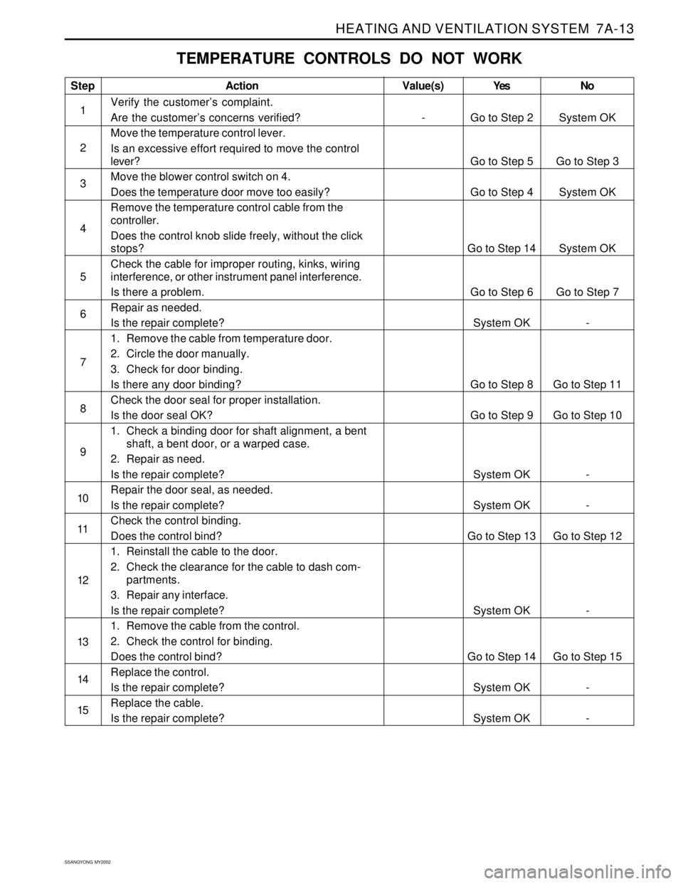
TEMPERATURE CONTROLS DO NOT WORK
Step
1
2
3
4
5
6
7
8
9
10
11
12
13
14
15Action
Verify the customer’s complaint.
Are the customer’s concerns verified?
Move the temperature control lever.
Is an excessive effort required to move the control
lever?
Move the blower control switch on 4.
Does the temperature door move too easily?
Remove the temperature control cable from the
controller.
Does the control knob slide freely, without the click
stops?
Check the cable for improper routing, kinks, wiring
interference, or other instrument panel interference.
Is there a problem.
Repair as needed.
Is the repair complete?
1. Remove the cable from temperature door.
2. Circle the door manually.
3. Check for door binding.
Is there any door binding?
Check the door seal for proper installation.
Is the door seal OK?
1. Check a binding door for shaft alignment, a bent
shaft, a bent door, or a warped case.
2. Repair as need.
Is the repair complete?
Repair the door seal, as needed.
Is the repair complete?
Check the control binding.
Does the control bind?
1. Reinstall the cable to the door.
2. Check the clearance for the cable to dash com-
partments.
3. Repair any interface.
Is the repair complete?
1. Remove the cable from the control.
2. Check the control for binding.
Does the control bind?
Replace the control.
Is the repair complete?
Replace the cable.
Is the repair complete?Yes
Go to Step 2
Go to Step 5
Go to Step 4
Go to Step 14
Go to Step 6
System OK
Go to Step 8
Go to Step 9
System OK
System OK
Go to Step 13
System OK
Go to Step 14
System OK
System OKNo
System OK
Go to Step 3
System OK
System OK
Go to Step 7
-
Go to Step 11
Go to Step 10
-
-
Go to Step 12
-
Go to Step 15
-
-Value(s)
-
Page 1515 of 2053
SSANGYONG MY2002
7A-14 HEATING AND VENTILATION SYSTEM
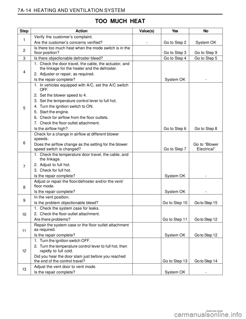
TOO MUCH HEAT
Step
1
2
3
4
5
6
7
8
9
10
11
12
13Action
Verify the customer’s complaint.
Are the customer’s concerns verified?
Is there too much heat when the mode switch is in the
floor position?
Is there objectionable defroster bleed?
1. Check the door travel, the cable, the actuator, and
the linkage for the heater and the defroster.
2. Adjuster or repair, as required.
Is the repair complete?
1. In vehicles equipped with A/C, set the A/C switch
OFF.
2. Set the blower speed to 4.
3. Set the temperature control lever to full hot.
4. Turn the ignition switch to ON.
5. Start the engine.
6. Check for airflow from the floor outlets.
7. Check the floor outlet attachment.
Is the airflow high?
Check for a change in airflow at different blower
speeds.
Does the airflow change as the setting for the blower
speed switch is changed?
1. Check the temperature door travel, the cable, and
the linkage.
2. Adjust to full hot.
3. Check for full hot.
Is the repair complete?
Adjust or repair the floor/defroster and/or the vent/
floor mode.
Is the repair complete?
In the vent position.
Is the problem objectionable bleed?
1. Check the system case for leaks.
2. Check the floor outlet attachment.
Are there problems?
Repair the system case or the floor outlet attachment
as required.
Is the repair complete?
1. Turn the ignition switch OFF.
2. Turn the temperature control lever to full hot, then
rapidly to full cold.
Did you hear the door slam just before you reached
the end of the control travel?
Adjust the vent door to vent mode.
Is the repair complete?Yes
Go to Step 2
Go to Step 3
Go to Step 4
System OK
Go to Step 6
Go to Step 7
System OK
System OK
Go to Step 10
Go to Step 11
System OK
Go to Step 13
System OKNo
System OK
Go to Step 9
Go to Step 5
-
Go to Step 8
Go to “Blower
Electrical”
-
-
Go to Step 15
Go to Step 12
Go to Step 12
Go to Step 14
-Value(s)
-