1997 SSANGYONG KORANDO heating
[x] Cancel search: heatingPage 1719 of 2053

SSANGYONG MY2002
9E-2 INSTRUMENTATION, DRIVER INFORMATION
DESCRIPTION AND OPERATION
CIGAR LIGHTER
The cigar lighter is located in the front portion of the
floor console. To use the lighter, push it in completely.
When the lighter is hot, it will release itsef from contact
with the heating element. The lighter and the heating
element can be damaged if the lighter does not fully
release itsef from the heating element.
ASHTRAY
The ashtray is located in the console. To access the
ashtray, pullit out of the ashtray housing. The ashtray
lamp will go on when the parking lamps or headlamps
are turned on.
INSTRUMENT PANEL VENTS
The center and the side vents in the instrument panel
can be adjusted up and down and from side to side.
The side vents can also be aimed toward the side
windows to defog them.
GLOVE BOX
The glove box can be opened by pulling upon the latch
handle.
DIGITAL CLOCK
The digital clock is located in the instrument cluster.
INSTRUMENT CLUSTER
The instrument cluster is located above the steering
column and in the instrument cluster trim panel. The
instrument cluster contains the instruments that
provide the driver with vehicle performance information.
The instrument cluster contains a speedometer, a
tachometer, an odometer, a trip odometer, a
temperature gauge, a fuel gauge, and several indicator
lamps. For replacement of the indicator lamp bulbs
contained in the instrument cluster, refer to “Instrument
Cluster Indicator Lamps Specifications” in the section.
SPEEDOMETER AND
TACHOMETER
The speedometer measures the speed of the vehicle
in km/h (with mph) or mph (with km/h). It consists of
an instrument cluster gauge connected to the vehicle
speed sensor on the transaxle output shaft. The
tachometer measures the engine’s speed in terms of
thousands of revolutions per minute. It consists of an
instrument cluster gauge connected to a sending unit
in the engine con-trol module. Do not operate the
engine in the red zone. Engine damage may occur.
TRIP ODOMETER
The trip odometer measures the distance the vehicle
has traveled since it was last reset. It consists of an
instrument cluster gauge connected to the sending unit
on the tasnsaxle output shaft. The trip oddometer can
be record the distance traveled from any starting point.
FUEL GAUGE
The fuel gauge consists of an instrument cluster gauge
connected to a sending unit in the fuel tank. The fuel
gauge indicates the quantity of fuel in the tank only
when the ignition is turned to ON or ACC. When the
ignition is turned to LOCK or START, the pointer may
come to rest at any position.
TEMPERATURE GAUGE
The temperature gauge consists of an instrument
cluster gauge connected to a temperature sensor that
is in con-tact with the circulating engine coolant. The
temperature gauge indicates the temperature of the
coolant. Prolonged driving or idling in very hot weather
may cause the pointer to move beyond the center of
the gauge. The engine is overheating if the pointer
moves into the red zone at the upper limit of the gauge.
INSTRUMENT CLUSTER
INDICATOR LAMPS
The instrument cluster contains indicator lamps that
indicatethe functioning of certain systems or the
existenceof potential problems with the operation of
the vehicle. The indicator lamps are replaceable. For
replacement of the indicator lamps contained in the
instrument cluster, refer to “instrument cluster indicator
lamps specifications” in this section.
CHIME MODULE
The chime module will sound to bring attention to one
or more of the following conditions:
The lights are on and the ignition not in ACC, ON,
or START.
The ignition key is in the ignition switch when the
driver’s side door is open.
The seat belt is unbuckled when the ignition is in
ACC, ON, or START.
Voltage is supplied at all times through the fuse block
to power the chime module.
Page 1868 of 2053
2-4 2-4 2-4 2-4
2-4
ELECTRICAL WIRING DIAGRAMS ELECTRICAL WIRING DIAGRAMSELECTRICAL WIRING DIAGRAMS ELECTRICAL WIRING DIAGRAMS
ELECTRICAL WIRING DIAGRAMS
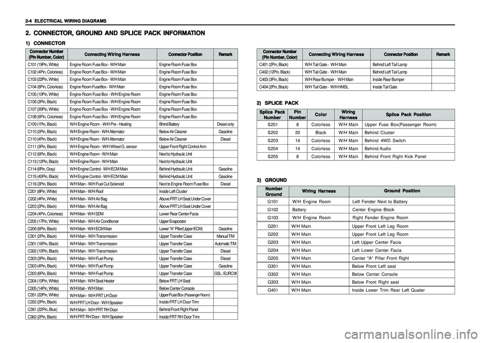
Engine Room Fuse Box - W/H Main
Engine Room Fuse Box - W/H Main
Engine Room Fuse Box - W/H Main
Engine Room FuseBox - W/H Main
Engine Room Fuse Box - W/H Engine Room
Engine Room Fuse Box - W/H Engine Room
Engine Room Fuse Box - W/H Engine Room
Engine Room Fuse Box - W/H Engine Room
W/H Engine Room - W/H Pre - Heating
W/H Engine Room - W/H Alternator
W/H Engine Room - W/H Alternator
W/H Engine Room - W/H Wheel G. sensor
W/H Engine Room - W/H Main
W/H Engine Room - W/H Main
W/H Engine Control - W/H ECM Main
W/H Engine Control - W/H ECM Main
W/H Main - W/H Fuel Cut Solenoid
W/H Main - W/H Roof
W/H Main - W/H Air Bag
W/H Main - W/H Air Bag
W/H Main - W/H SDM
W/H Main - W/H Air Conditioner
W/H Main - W/H ECM Main
W/H Main - W/H Transmission
W/H Main - W/H Transmission
W/H Main - W/H Transmission
W/H Main - W/H Fuel Pump
W/H Main - W/H Fuel Pump
W/H Main - W/H Fuel Pump
W/H Main - W/H Seat Heater
W/H Main - W/H Main
W/H Main - W/H FRT LH Door
W/H FRT LH Door - W/H Speaker
W/H Main - W/H FRT RH Door
W/H FRT RH Door - W/H Speaker
G201W/H Main Upper Front Left Leg Room
G202W/H Main Upper Front Left Leg Room
G203W/H Main Left Upper Center Facia
G204W/H Main Left Lower Center Facia
G205W/H Main Center "A" Pillar Front Right
G301W/H Main Below Front Left seat
G302W/H Main Below Center Console
G303W/H Main Below Front Right seat
G401W/H Main Inside Lower Trim Rear Left Quater
Engine Room Fuse Box
Engine Room Fuse Box
Engine Room Fuse Box
Engine Room Fuse Box
Engine Room Fuse Box
Engine Room Fuse Box
Engine Room Fuse Box
Engine Room Fuse Box
Bhind Battery
Below Air Cleaner
Below Air Cleaner
Upper Front Right Control Arm
Next to Hydraulic Unit
Next to Hydraulic Unit
Behind Hydraulic Unit
Behind Hydraulic Unit
Next to Engine Room Fuse Box
Inside Left Cluster
Above FRT LH Seat Under Cover
Above FRT LH Seat Under Cover
Lower Rear Center Facia
Upper Evaporator
Lower "A" Piller(Upper ECM)
Upper Transfer Case
Upper Transfer Case
Upper Transfer Case
Upper Transfer Case
Upper Transfer Case
Upper Transfer Case
Below FRT LH Seat
Below Center Console
Upper Fuse Box
(Passenger Room)
Inside FRT LH Door Trim
Behind Front Right Panel
Inside FRT RH Door Trim
2. 2.2. 2.
2.
CONNECT CONNECTCONNECT CONNECT
CONNECT
OR, OR,OR, OR,
OR,
GR GR GR GR
GR
OUND AND SPLICE PA OUND AND SPLICE PAOUND AND SPLICE PA OUND AND SPLICE PA
OUND AND SPLICE PA
CK INFORMA CK INFORMACK INFORMA CK INFORMA
CK INFORMA
TION TIONTION TION
TION1) 1)1) 1)
1)
CONNECTOR CONNECTORCONNECTOR CONNECTOR
CONNECTORConnector Number Connector NumberConnector Number Connector Number
Connector Number
(Pin Number, Color) (Pin Number, Color)(Pin Number, Color) (Pin Number, Color)
(Pin Number, Color)Connecting Connecting Connecting Connecting
Connecting
Wiring Harness Wiring HarnessWiring Harness Wiring Harness
Wiring Harness
Connector Position Connector PositionConnector Position Connector Position
Connector Position
C101 (19Pin, White)
C102 (4Pin, Colorless)
C103 (22Pin, White)
C104 (8Pin, Colorless)
C105 (10Pin, White)
C106 (3Pin, Black)
C107 (20Pin, White)
C108 (6Pin, Colorless)
C109 (1Pin, Black)
C110 (2Pin, Black)
C110 (4Pin, Black)
C111 (3Pin, Black)
C112 (6Pin, Black)
C113 (12Pin, Black)
C114 (6Pin, Gray)
C115 (40Pin, Black)
C116 (3Pin, Black)
C201 (8Pin, White)
C202 (4Pin, White)
C203 (2Pin, Black)
C204 (4Pin, Colorless)
C205 (17Pin, White)
C206 (6Pin, Black)
C301 (2Pin, Black)
C301 (16Pin, Black)
C302 (10Pin, Black)
C303 (3Pin, Black)
C303 (4Pin, Black)
C303 (6Pin, Black)
C304 (10Pin, White)
C305 (14Pin, White)
C351 (22Pin, White)
C352 (2Pin, Black)
C361 (22Pin, Blue)
C362 (2Pin, Black)
2) 2)2) 2)
2)
SPLICE PACK SPLICE PACKSPLICE PACK SPLICE PACK
SPLICE PACK
S201
S202
S203
S204
S205Splice Pack Position Splice Pack PositionSplice Pack Position Splice Pack Position
Splice Pack Position Wiring WiringWiring Wiring
Wiring
Harness HarnessHarness Harness
Harness Color ColorColor Color
Color Splice Pack Splice PackSplice Pack Splice Pack
Splice Pack
Number NumberNumber Number
Number
Colorless
Black
Colorless
Colorless
ColorlessW/H Main
W/H Main
W/H Main
W/H Main
W/H MainUpper Fuse Box(Passenger Room)
Behind Cluster
Behind 4WD Switch
Behind Audio
Behind Front Right Kick Panel
Remark RemarkRemark Remark
Remark
Diesel only
Gasoline
Diesel
Gasoline
Gasoline
Diesel
Gasoline
Manual T/M
Automatic T/M
Diesel
Diesel
Gasoline
GSL : EURO IIIBehind Left Tail Lamp
Behind Left Tail Lamp
Inside Rear Bumper
Inside Tail Gate
Connector Number Connector NumberConnector Number Connector Number
Connector Number
(Pin Number, Color) (Pin Number, Color)(Pin Number, Color) (Pin Number, Color)
(Pin Number, Color)Connecting Connecting Connecting Connecting
Connecting
Wiring Harness Wiring HarnessWiring Harness Wiring Harness
Wiring Harness
Connector Position Connector PositionConnector Position Connector Position
Connector Position
C401 (2Pin, Black)
C402 (12Pin, Black)
C403 (3Pin, Black)
C404 (2Pin, Black)W/H Tail Gate - W/H Main
W/H Tail Gate - W/H Main
W/H Rear Bumper - W/H Main
W/H Tail Gate - W/H HMSL
Remark RemarkRemark Remark
Remark
3) 3)3) 3)
3)
GROUND GROUNDGROUND GROUND
GROUND
G101
G102
G103Ground Position Ground PositionGround Position Ground Position
Ground Position
Wiring Harness Wiring HarnessWiring Harness Wiring Harness
Wiring Harness Number NumberNumber Number
Number
Ground GroundGround Ground
Ground
W/H Engine Room
Battery
W/H Engine RoomLeft Fender Next to Battery
Center Engine Block
Right Fender Engine Room
Pin PinPin Pin
Pin
Number NumberNumber Number
Number
8
20
14
14
8
Page 1870 of 2053
2-6 2-6 2-6 2-6
2-6
ELECTRICAL WIRING DIAGRAMS ELECTRICAL WIRING DIAGRAMSELECTRICAL WIRING DIAGRAMS ELECTRICAL WIRING DIAGRAMS
ELECTRICAL WIRING DIAGRAMS3. 3.3. 3.
3.
WIRING HARNESS & CONNECT WIRING HARNESS & CONNECTWIRING HARNESS & CONNECT WIRING HARNESS & CONNECT
WIRING HARNESS & CONNECT
OR & GR OR & GROR & GR OR & GR
OR & GR
OUND LOCA OUND LOCAOUND LOCA OUND LOCA
OUND LOCA
TION TIONTION TION
TION1) 1)1) 1)
1)
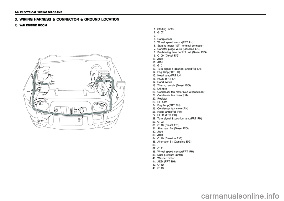
W/H ENGINE ROOM W/H ENGINE ROOMW/H ENGINE ROOM W/H ENGINE ROOM
W/H ENGINE ROOM
1. Starting motor
2. G102
3. -
4. Compressor
5. Wheel speed sensor(FRT LH)
6. Starting motor "ST" terminal connector
7. Canister purge valve (Gasoline E/G)
8. Pre-heating time control unit (Diesel E/G)
9. C109 (Diesel E/G)
10. J102
11. J101
12. G101
13. Turn signal & position lamp(FRT LH)
14. Fog lamp(FRT LH)
15. Head lamp(FRT LH)
16. HLLD (FRT LH)
17. Hood switch
18. Thermo switch (Diesel E/G)
19. LH horn
20. Condenser fan motor-Non A/conditioner
21. Condenser fan motor(LH)
22. Resistor
23. RH horn
24. Fog lamp(FRT RH)
25. Condenser fan motor(RH)
26. Head lamp(FRT RH)
27. HLLD (FRT RH)
28. Turn signal & position lamp(FRT RH)
29. G103
30. C110 (Diesel E/G)
31. Alternator B+ (Diesel E/G)
32. J104
33. J103
34. C110 (Gasoline E/G)
35. Alternator B+ (Gasoline E/G)
36. -
37. C111
38. Wheel speed sensor(FRT RH)
39. Dual pressure switch
40. Washer motor
41. ADD (FRT RH)
42. C112
43. C113
FUSE &RELAY BOX
42
43
41
40
393435
37303138
2928
25
26
24
23
2221201918
17
1516
13
12111089
7
6
5
4321
14
27
3233
Page 1877 of 2053
ELECTRICAL WIRING DIAGRAMS ELECTRICAL WIRING DIAGRAMSELECTRICAL WIRING DIAGRAMS ELECTRICAL WIRING DIAGRAMS
ELECTRICAL WIRING DIAGRAMS
2-13 2-13 2-13 2-13
2-13
9) 9)9) 9)
9)
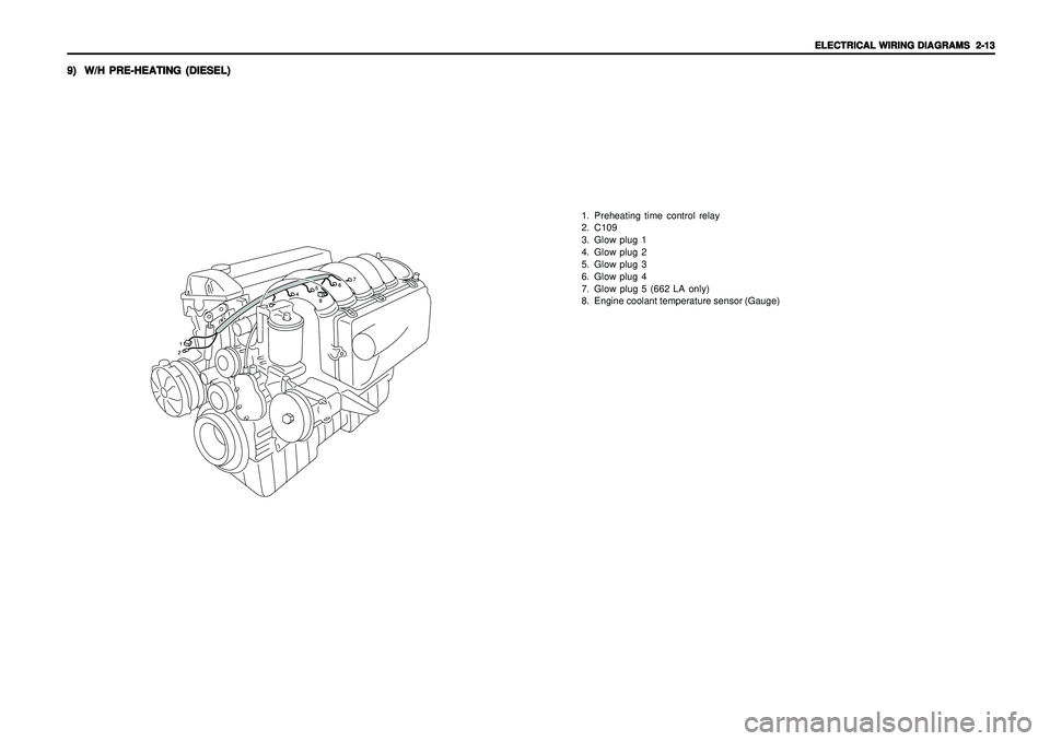
W/H PRE-HEATING (DIESEL) W/H PRE-HEATING (DIESEL)W/H PRE-HEATING (DIESEL) W/H PRE-HEATING (DIESEL)
W/H PRE-HEATING (DIESEL)
1. Preheating time control relay
2. C109
3. Glow plug 1
4. Glow plug 2
5. Glow plug 3
6. Glow plug 4
7. Glow plug 5 (662 LA only)
8. Engine coolant temperature sensor (Gauge)
Page 1893 of 2053
USAGE AND CAPACITY OF FUSES IN FUSE BOX USAGE AND CAPACITY OF FUSES IN FUSE BOX USAGE AND CAPACITY OF FUSES IN FUSE BOX USAGE AND CAPACITY OF FUSES IN FUSE BOX
USAGE AND CAPACITY OF FUSES IN FUSE BOX
4-3 4-34-3 4-3
4-3
2. 2.2. 2.
2.
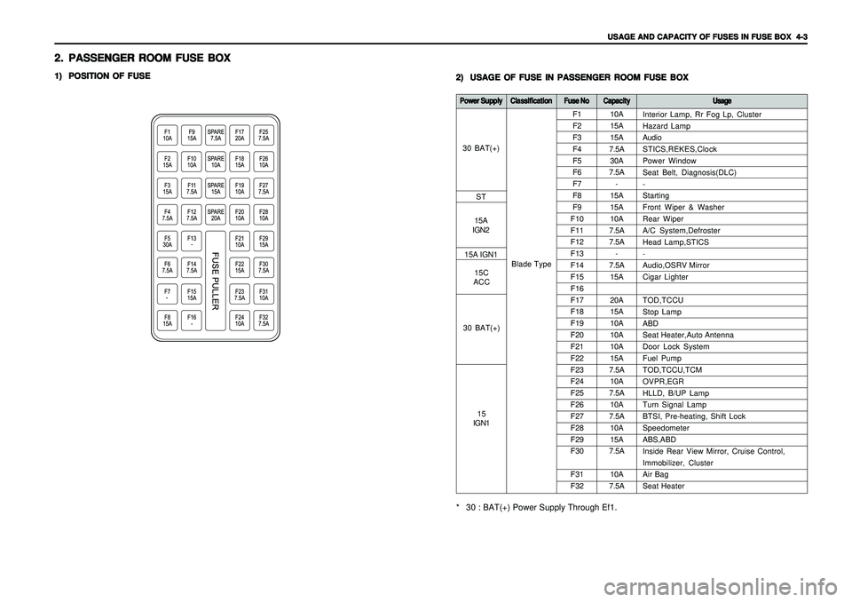
PASSENGER ROOM FUSE BOX PASSENGER ROOM FUSE BOXPASSENGER ROOM FUSE BOX PASSENGER ROOM FUSE BOX
PASSENGER ROOM FUSE BOX1) 1)1) 1)
1)
POSITION OF FUSE POSITION OF FUSEPOSITION OF FUSE POSITION OF FUSE
POSITION OF FUSE
2) 2)2) 2)
2)
USAGE OF FUSE IN PASSENGER ROOM FUSE BOX USAGE OF FUSE IN PASSENGER ROOM FUSE BOXUSAGE OF FUSE IN PASSENGER ROOM FUSE BOX USAGE OF FUSE IN PASSENGER ROOM FUSE BOX
USAGE OF FUSE IN PASSENGER ROOM FUSE BOX
10A
15A
15A
7.5A
30A
7.5A
-
15A
15A
10A
7.5A
7.5A
-
7.5A
15A
20A
15A
10A
10A
10A
15A
7.5A
10A
7.5A
10A
7.5A
10A
15A
7.5A
10A
7.5A F1
F2
F3
F4
F5
F6
F7
F8
F9
F10
F11
F12
F13
F14
F15
F16
F17
F18
F19
F20
F21
F22
F23
F24
F25
F26
F27
F28
F29
F30
F31
F32
Power Supply Power SupplyPower Supply Power Supply
Power Supply
Classification ClassificationClassification Classification
Classification
Fuse No Fuse NoFuse No Fuse No
Fuse No
Capacity CapacityCapacity Capacity
Capacity
Usage UsageUsage Usage
Usage* 30 : BAT(+) Power Supply Through Ef1.
Blade TypeInterior Lamp, Rr Fog Lp, Cluster
Hazard Lamp
Audio
STICS,REKES,Clock
Power Window
Seat Belt, Diagnosis(DLC)
-
Starting
Front Wiper & Washer
Rear Wiper
A/C System,Defroster
Head Lamp,STICS
-
Audio,OSRV Mirror
Cigar Lighter
TOD,TCCU
Stop Lamp
ABD
Seat Heater,Auto Antenna
Door Lock System
Fuel Pump
TOD,TCCU,TCM
OVPR,EGR
HLLD, B/UP Lamp
Turn Signal Lamp
BTSI, Pre-heating, Shift Lock
Speedometer
ABS,ABD
Inside Rear View Mirror, Cruise Control,
Immobilizer, Cluster
Air Bag
Seat Heater
30 BAT(+)
ST
15A
IGN2
30 BAT(+)15C
ACC 15A IGN1
15
IGN1
Page 1910 of 2053
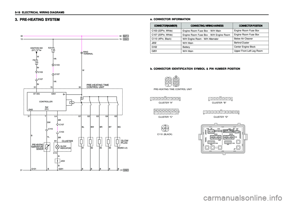
5-16 5-16 5-16 5-16
5-16
ELECTRICAL WIRING DIAGRAMS ELECTRICAL WIRING DIAGRAMSELECTRICAL WIRING DIAGRAMS ELECTRICAL WIRING DIAGRAMS
ELECTRICAL WIRING DIAGRAMS
a. a.a. a.
a.
CONNECTOR INFORMATION CONNECTOR INFORMATIONCONNECTOR INFORMATION CONNECTOR INFORMATION
CONNECTOR INFORMATION
b. b.b. b.
b.
CONNECTOR IDENTIFICATION SYMBOL & PIN NUMBER POSITION CONNECTOR IDENTIFICATION SYMBOL & PIN NUMBER POSITIONCONNECTOR IDENTIFICATION SYMBOL & PIN NUMBER POSITION CONNECTOR IDENTIFICATION SYMBOL & PIN NUMBER POSITION
CONNECTOR IDENTIFICATION SYMBOL & PIN NUMBER POSITION
3. 3.3. 3.
3.
PRE-HEA PRE-HEAPRE-HEA PRE-HEA
PRE-HEA
TING SYSTEM TING SYSTEMTING SYSTEM TING SYSTEM
TING SYSTEM
PRE-HEATING TIME CONTROL UNIT
CLUSTER "B" CLUSTER "A"
CLUSTER "C" CLUSTER "D"
C110 (BLACK)
C103 (22Pin, White)
C107 (20Pin, White)
C110 (4Pin, Black)
J202
G102
G201CONNECTOR(NUMBER) CONNECTOR(NUMBER)CONNECTOR(NUMBER) CONNECTOR(NUMBER)
CONNECTOR(NUMBER)
CONNECTING. WIRING HARNESS CONNECTING. WIRING HARNESSCONNECTING. WIRING HARNESS CONNECTING. WIRING HARNESS
CONNECTING. WIRING HARNESS
Engine Room Fuse Box - W/H Main
Engine Room Fuse Box - W/H Engine Room
W/H Engine Room - W/H Alternator
W/H Main
Battery
W/H Main
CONNECTOR POSITION CONNECTOR POSITIONCONNECTOR POSITION CONNECTOR POSITION
CONNECTOR POSITION
Engine Room Fuse Box
Engine Room Fuse Box
Below Air Cleaner
Behind Cluster
Center Engine Block
Upper Front Left Leg Room
Page 1911 of 2053
ELECTRICAL WIRING DIAGRAMS ELECTRICAL WIRING DIAGRAMSELECTRICAL WIRING DIAGRAMS ELECTRICAL WIRING DIAGRAMS
ELECTRICAL WIRING DIAGRAMS
5-17 5-17 5-17 5-17
5-17
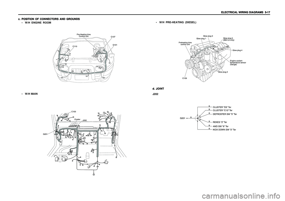
c. c.c. c.
c.
POSITION OF CONNECTORS AND GROUNDS POSITION OF CONNECTORS AND GROUNDSPOSITION OF CONNECTORS AND GROUNDS POSITION OF CONNECTORS AND GROUNDS
POSITION OF CONNECTORS AND GROUNDS
W/H ENGINE ROOM
d. d.d. d.
d.
JOINT JOINTJOINT JOINT
JOINT
J202 W/H MAINW/H PRE-HEATING (DIESEL)
Page 1988 of 2053
5-94 5-94 5-94 5-94
5-94
ELECTRICAL WIRING DIAGRAMS ELECTRICAL WIRING DIAGRAMSELECTRICAL WIRING DIAGRAMS ELECTRICAL WIRING DIAGRAMS
ELECTRICAL WIRING DIAGRAMS
C109 (1Pin,Black)
C110 (2Pin, Black)
C110 (4Pin, Black)
C113 (12Pin,Black)
C303 (3Pin, Black)
S202 (20Pin,Black)
J202
G201
G202
G302
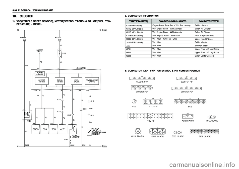
18. 18.18. 18.
18.
CLUSTER CLUSTERCLUSTER CLUSTER
CLUSTER1) 1)1) 1)
1)
VSS(VEHICLE SPEED SENSOR), METER(SPEEDO, TACHO) & GAUGE(FUEL, TEM- VSS(VEHICLE SPEED SENSOR), METER(SPEEDO, TACHO) & GAUGE(FUEL, TEM-VSS(VEHICLE SPEED SENSOR), METER(SPEEDO, TACHO) & GAUGE(FUEL, TEM- VSS(VEHICLE SPEED SENSOR), METER(SPEEDO, TACHO) & GAUGE(FUEL, TEM-
VSS(VEHICLE SPEED SENSOR), METER(SPEEDO, TACHO) & GAUGE(FUEL, TEM-
PERATURE) - DIESEL PERATURE) - DIESELPERATURE) - DIESEL PERATURE) - DIESEL
PERATURE) - DIESEL
b. b.b. b.
b.
CONNECTOR IDENTIFICATION SYMBOL & PIN NUMBER POSITION CONNECTOR IDENTIFICATION SYMBOL & PIN NUMBER POSITIONCONNECTOR IDENTIFICATION SYMBOL & PIN NUMBER POSITION CONNECTOR IDENTIFICATION SYMBOL & PIN NUMBER POSITION
CONNECTOR IDENTIFICATION SYMBOL & PIN NUMBER POSITION
STICS "B"
VSS
ALTERNATOR
ECS
FUEL GUAGE
TCM "B"
C113 (BLACK)
S202 (BLACK)
CLUSTER "B"
CLUSTER "A"
CLUSTER "C" CLUSTER "D"
C303 (BLACK)
C110 (BLACK)
a. a.a. a.
a.
CONNECTOR INFORMATION CONNECTOR INFORMATIONCONNECTOR INFORMATION CONNECTOR INFORMATION
CONNECTOR INFORMATION
CONNECTOR(NUMBER) CONNECTOR(NUMBER)CONNECTOR(NUMBER) CONNECTOR(NUMBER)
CONNECTOR(NUMBER)
CONNECTING. WIRING HARNESS CONNECTING. WIRING HARNESSCONNECTING. WIRING HARNESS CONNECTING. WIRING HARNESS
CONNECTING. WIRING HARNESS
Engine Room Fuse Box - W/H Pre Heating
W/H Engine Room - W/H Alternator
W/H Engine Room - W/H Alternator
W/H Engine Room - W/H Main
W/H Main - W/H Fuel Pump
W/H Main
W/H Main
W/H Main
W/H Main
W/H Main
CONNECTOR POSITION CONNECTOR POSITIONCONNECTOR POSITION CONNECTOR POSITION
CONNECTOR POSITION
Behind Battery
Below Air Cleaner
Below Air Cleaner
Next to Hydaulic Unit
Upper Transfer Case
Behind Cluster
Behind Cluster
Upper Front Left Leg Room
Upper Front Left Leg Room
Below Center Console