1997 SSANGYONG KORANDO START CIRCUIT
[x] Cancel search: START CIRCUITPage 1375 of 2053
TRANSFER CASE 5D1-5
SSANGYONG MY2002
The motor reaches its destination.
The motor is on for 5 seconds without reaching its
destination. The shift has failed and the TCCU will
respond as default mode.
A fault occurs with either the motor or position
encoder. Refer to the diagnosis requirement.
When the motor is energized, the Ignition, 4H/4L
switch, propeller shaft speeds, and transmission
neutral inputs are ignored.
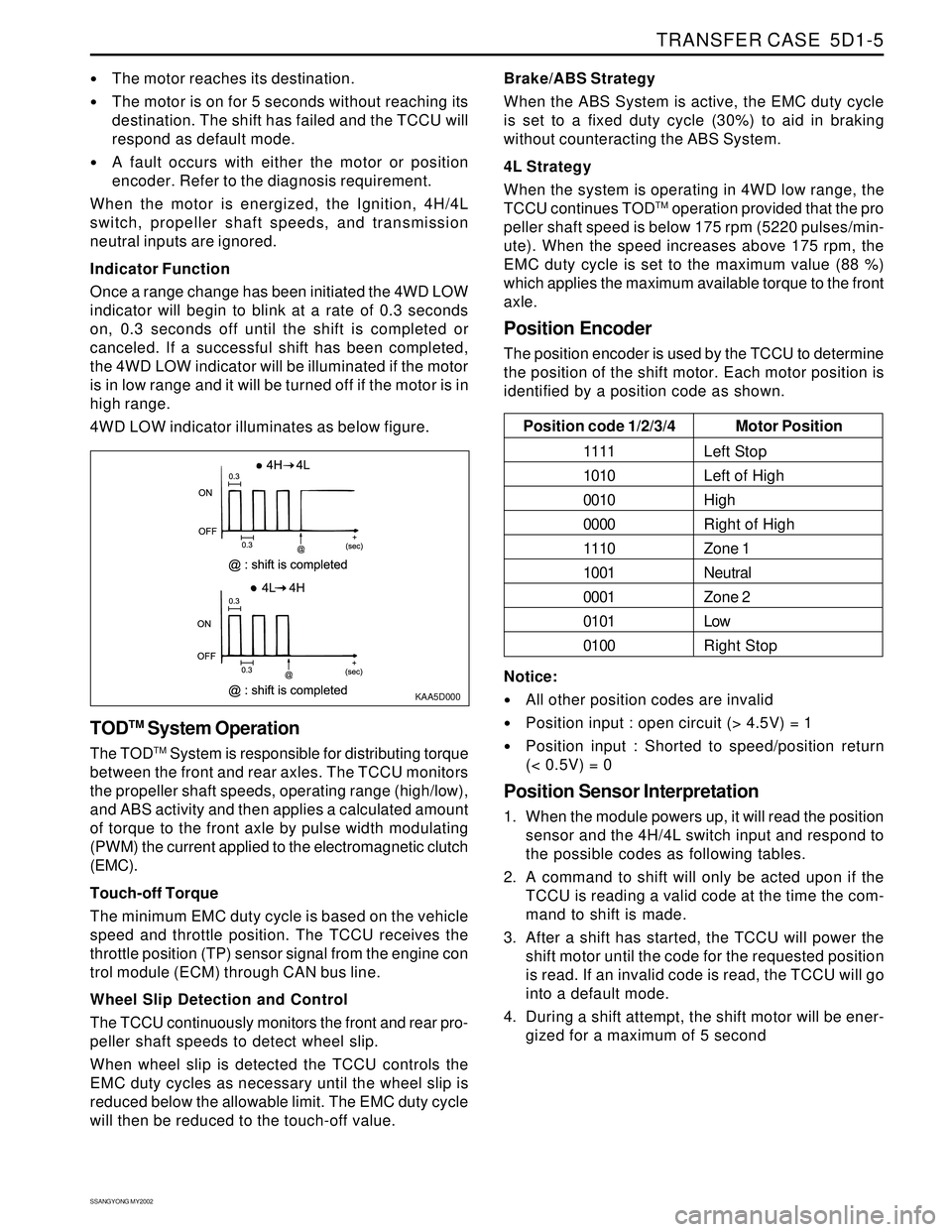
Indicator Function
Once a range change has been initiated the 4WD LOW
indicator will begin to blink at a rate of 0.3 seconds
on, 0.3 seconds off until the shift is completed or
canceled. If a successful shift has been completed,
the 4WD LOW indicator will be illuminated if the motor
is in low range and it will be turned off if the motor is in
high range.
4WD LOW indicator illuminates as below figure.
KAA5D000
TODTM System Operation
The TODTM System is responsible for distributing torque
between the front and rear axles. The TCCU monitors
the propeller shaft speeds, operating range (high/low),
and ABS activity and then applies a calculated amount
of torque to the front axle by pulse width modulating
(PWM) the current applied to the electromagnetic clutch
(EMC).
Touch-off Torque
The minimum EMC duty cycle is based on the vehicle
speed and throttle position. The TCCU receives the
throttle position (TP) sensor signal from the engine con
trol module (ECM) through CAN bus line.
Wheel Slip Detection and Control
The TCCU continuously monitors the front and rear pro-
peller shaft speeds to detect wheel slip.
When wheel slip is detected the TCCU controls the
EMC duty cycles as necessary until the wheel slip is
reduced below the allowable limit. The EMC duty cycle
will then be reduced to the touch-off value.Brake/ABS Strategy
When the ABS System is active, the EMC duty cycle
is set to a fixed duty cycle (30%) to aid in braking
without counteracting the ABS System.
4L Strategy
When the system is operating in 4WD low range, the
TCCU continues TOD
TM operation provided that the pro
peller shaft speed is below 175 rpm (5220 pulses/min-
ute). When the speed increases above 175 rpm, the
EMC duty cycle is set to the maximum value (88 %)
which applies the maximum available torque to the front
axle.
Position Encoder
The position encoder is used by the TCCU to determine
the position of the shift motor. Each motor position is
identified by a position code as shown.
Motor Position
Left Stop
Left of High
High
Right of High
Zone 1
Neutral
Zone 2
Low
Right Stop Position code 1/2/3/4
1111
1010
0010
0000
1110
1001
0001
0101
0100
Notice:
All other position codes are invalid
Position input : open circuit (> 4.5V) = 1
Position input : Shorted to speed/position return
(< 0.5V) = 0
Position Sensor Interpretation
1. When the module powers up, it will read the position
sensor and the 4H/4L switch input and respond to
the possible codes as following tables.
2. A command to shift will only be acted upon if the
TCCU is reading a valid code at the time the com-
mand to shift is made.
3. After a shift has started, the TCCU will power the
shift motor until the code for the requested position
is read. If an invalid code is read, the TCCU will go
into a default mode.
4. During a shift attempt, the shift motor will be ener-
gized for a maximum of 5 second
Page 1384 of 2053
SSANGYONG MY2002
5D1-14 TRANSFER CASE
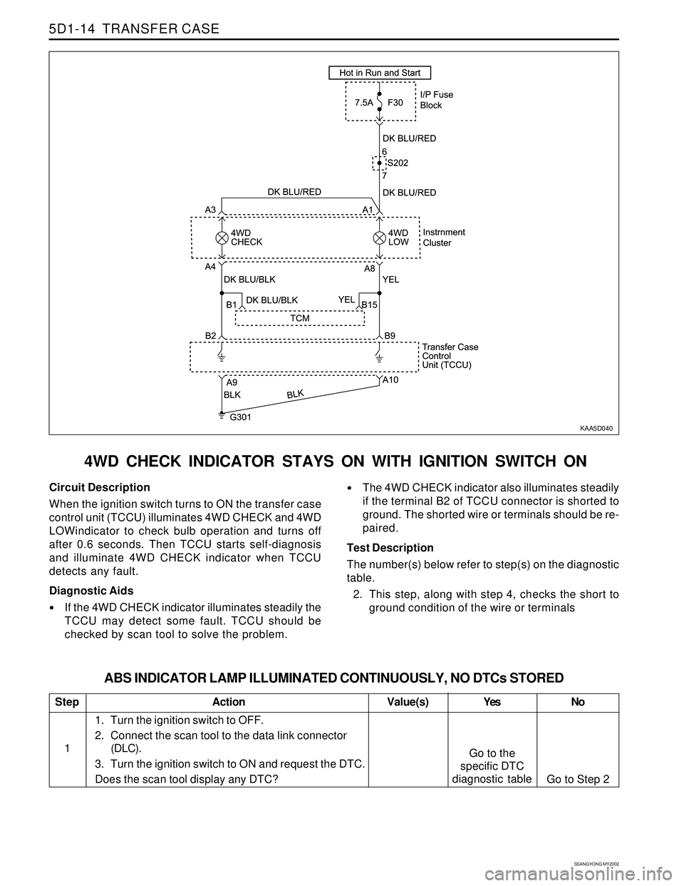
4WD CHECK INDICATOR STAYS ON WITH IGNITION SWITCH ON
KAA5D040
Circuit Description
When the ignition switch turns to ON the transfer case
control unit (TCCU) illuminates 4WD CHECK and 4WD
LOWindicator to check bulb operation and turns off
after 0.6 seconds. Then TCCU starts self-diagnosis
and illuminate 4WD CHECK indicator when TCCU
detects any fault.
Diagnostic Aids
If the 4WD CHECK indicator illuminates steadily the
TCCU may detect some fault. TCCU should be
checked by scan tool to solve the problem.
The 4WD CHECK indicator also illuminates steadily
if the terminal B2 of TCCU connector is shorted to
ground. The shorted wire or terminals should be re-
paired.
Test Description
The number(s) below refer to step(s) on the diagnostic
table.
2. This step, along with step 4, checks the short to
ground condition of the wire or terminals
Step
1
ABS INDICATOR LAMP ILLUMINATED CONTINUOUSLY, NO DTCs STORED
Action Yes
Go to the
specific DTC
diagnostic tableNo
Go to Step 2 Value(s)
1. Turn the ignition switch to OFF.
2. Connect the scan tool to the data link connector
(DLC).
3. Turn the ignition switch to ON and request the DTC.
Does the scan tool display any DTC?
Page 1386 of 2053
SSANGYONG MY2002
5D1-16 TRANSFER CASE
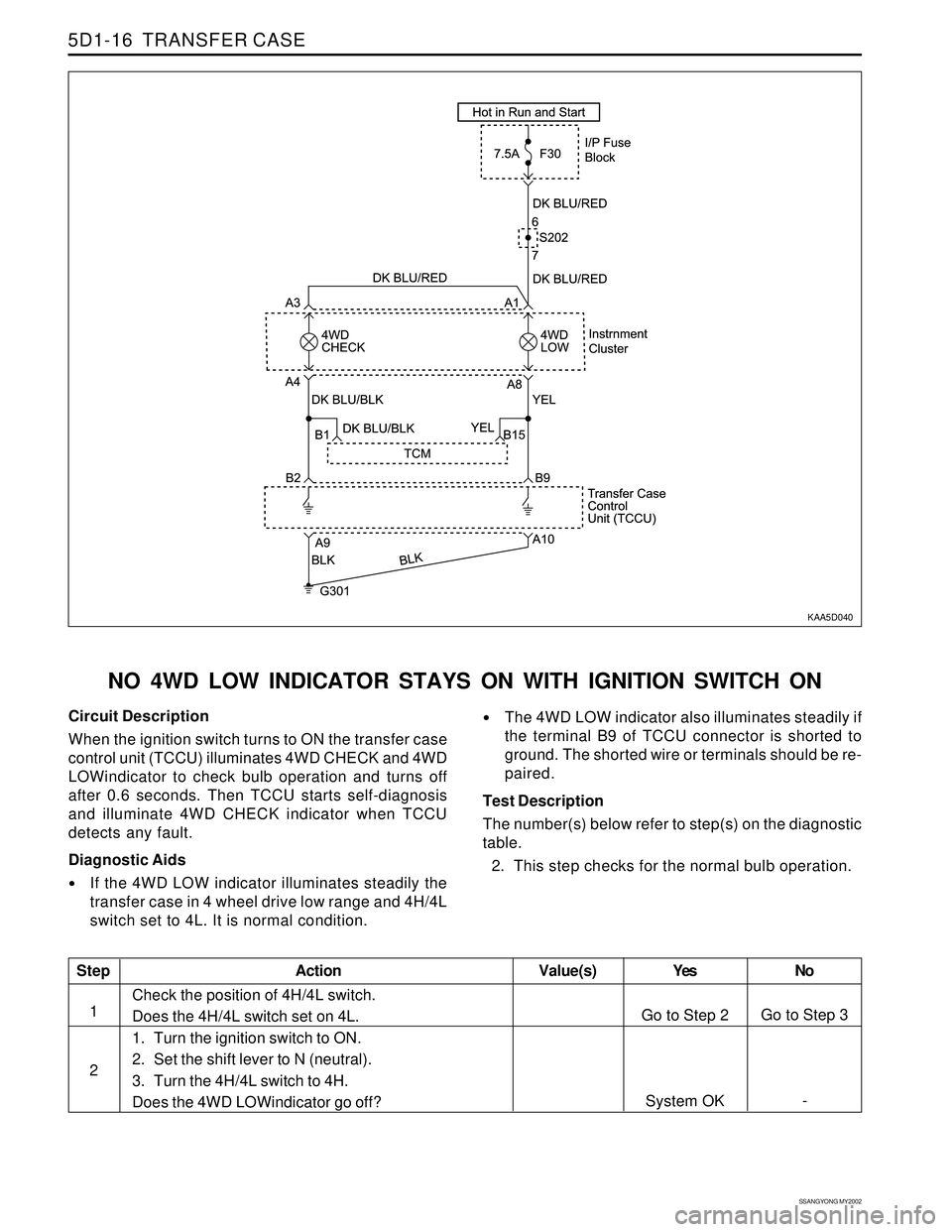
KAA5D040
NO 4WD LOW INDICATOR STAYS ON WITH IGNITION SWITCH ON
Circuit Description
When the ignition switch turns to ON the transfer case
control unit (TCCU) illuminates 4WD CHECK and 4WD
LOWindicator to check bulb operation and turns off
after 0.6 seconds. Then TCCU starts self-diagnosis
and illuminate 4WD CHECK indicator when TCCU
detects any fault.
Diagnostic Aids
If the 4WD LOW indicator illuminates steadily the
transfer case in 4 wheel drive low range and 4H/4L
switch set to 4L. It is normal condition.
The 4WD LOW indicator also illuminates steadily if
the terminal B9 of TCCU connector is shorted to
ground. The shorted wire or terminals should be re-
paired.
Test Description
The number(s) below refer to step(s) on the diagnostic
table.
2. This step checks for the normal bulb operation.
Step
1
2
Action Yes
Go to Step 2
System OKNo
Go to Step 3
- Value(s)
Check the position of 4H/4L switch.
Does the 4H/4L switch set on 4L.
1. Turn the ignition switch to ON.
2. Set the shift lever to N (neutral).
3. Turn the 4H/4L switch to 4H.
Does the 4WD LOWindicator go off?
Page 1590 of 2053
SUPPLEMENTAL RESTRAINTS SYSTEM 8B-5
SSANGYONG MY2002
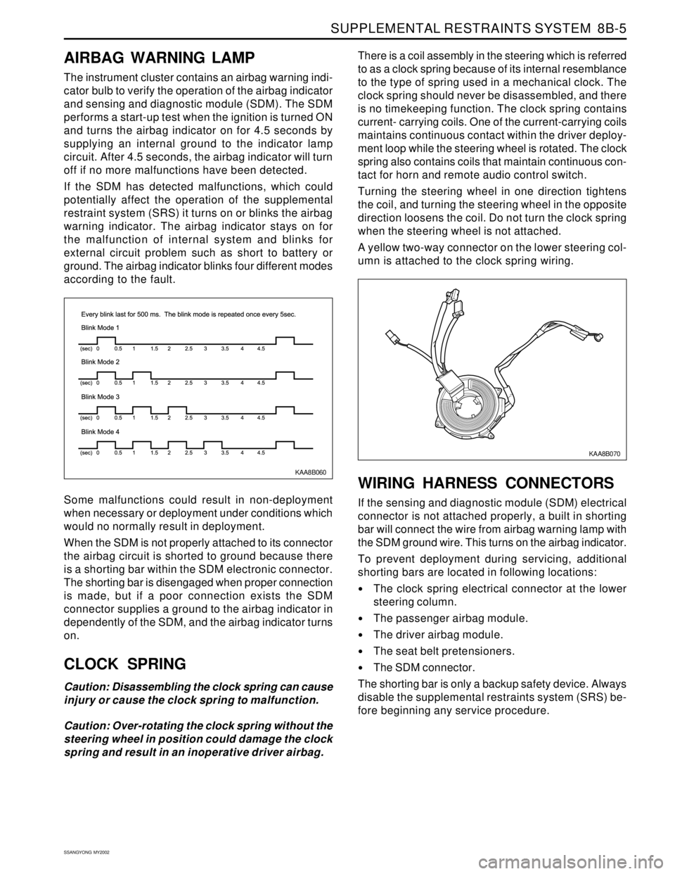
KAA8B060
AIRBAG WARNING LAMP
The instrument cluster contains an airbag warning indi-
cator bulb to verify the operation of the airbag indicator
and sensing and diagnostic module (SDM). The SDM
performs a start-up test when the ignition is turned ON
and turns the airbag indicator on for 4.5 seconds by
supplying an internal ground to the indicator lamp
circuit. After 4.5 seconds, the airbag indicator will turn
off if no more malfunctions have been detected.
If the SDM has detected malfunctions, which could
potentially affect the operation of the supplemental
restraint system (SRS) it turns on or blinks the airbag
warning indicator. The airbag indicator stays on for
the malfunction of internal system and blinks for
external circuit problem such as short to battery or
ground. The airbag indicator blinks four different modes
according to the fault.
Some malfunctions could result in non-deployment
when necessary or deployment under conditions which
would no normally result in deployment.
When the SDM is not properly attached to its connector
the airbag circuit is shorted to ground because there
is a shorting bar within the SDM electronic connector.
The shorting bar is disengaged when proper connection
is made, but if a poor connection exists the SDM
connector supplies a ground to the airbag indicator in
dependently of the SDM, and the airbag indicator turns
on.
CLOCK SPRING
Caution: Disassembling the clock spring can cause
injury or cause the clock spring to malfunction.
Caution: Over-rotating the clock spring without the
steering wheel in position could damage the clock
spring and result in an inoperative driver airbag.There is a coil assembly in the steering which is referred
to as a clock spring because of its internal resemblance
to the type of spring used in a mechanical clock. The
clock spring should never be disassembled, and there
is no timekeeping function. The clock spring contains
current- carrying coils. One of the current-carrying coils
maintains continuous contact within the driver deploy-
ment loop while the steering wheel is rotated. The clock
spring also contains coils that maintain continuous con-
tact for horn and remote audio control switch.
Turning the steering wheel in one direction tightens
the coil, and turning the steering wheel in the opposite
direction loosens the coil. Do not turn the clock spring
when the steering wheel is not attached.
A yellow two-way connector on the lower steering col-
umn is attached to the clock spring wiring.
WIRING HARNESS CONNECTORS
If the sensing and diagnostic module (SDM) electrical
connector is not attached properly, a built in shorting
bar will connect the wire from airbag warning lamp with
the SDM ground wire. This turns on the airbag indicator.
To prevent deployment during servicing, additional
shorting bars are located in following locations:
The clock spring electrical connector at the lower
steering column.
The passenger airbag module.
The driver airbag module.
The seat belt pretensioners.
The SDM connector.
The shorting bar is only a backup safety device. Always
disable the supplemental restraints system (SRS) be-
fore beginning any service procedure.
KAA8B070
Page 1595 of 2053
SSANGYONG MY2002
8B-10 SUPPLEMENTAL RESTRAINTS SYSTEM
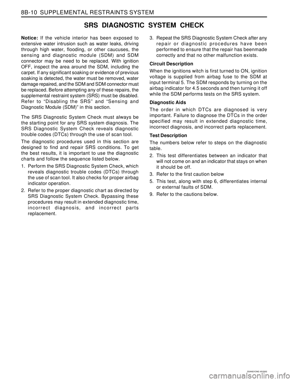
SRS DIAGNOSTIC SYSTEM CHECK
Notice: If the vehicle interior has been exposed to
extensive water intrusion such as water leaks, driving
through high water, flooding, or other caucuses, the
sensing and diagnostic module (SDM) and SDM
connector may be need to be replaced. With ignition
OFF, inspect the area around the SDM, including the
carpet. If any significant soaking or evidence of previous
soaking is detected, the water must be removed, water
damage repaired, and the SDM and SDM connector must
be replaced. Before attempting any of these repairs, the
supplemental restraint system (SRS) must be disabled.
Refer to “Disabling the SRS” and “Sensing and
Diagnostic Module (SDM)” in this section.
The SRS Diagnostic System Check must always be
the starting point for any SRS system diagnosis. The
SRS Diagnostic System Check reveals diagnostic
trouble codes (DTCs) through the use of scan tool.
The diagnostic procedures used in this section are
designed to find and repair SRS conditions. To get
the best results, it is important to use the diagnostic
charts and follow the sequence listed below.
1. Perform the SRS Diagnostic System Check, which
reveals diagnostic trouble codes (DTCs) through
the use of scan tool. It also checks for proper airbag
indicator operation.
2. Refer to the proper diagnostic chart as directed by
SRS Diagnostic System Check. Bypassing these
procedures may result in extended diagnostic time,
incorrect diagnosis, and incorrect parts
replacement.3. Repeat the SRS Diagnostic System Check after any
repair or diagnostic procedures have been
performed to ensure that the repair has beenmade
correctly and that no other malfunction exists.
Circuit Description
When the ignitions witch is first turned to ON, ignition
voltage is supplied from airbag fuse to the SDM at
input terminal 5. The SDM responds by turning on the
airbag indicator for 4.5 seconds and then turning it off
while the SDM performs tests on the SRS system.
Diagnostic Aids
The order in which DTCs are diagnosed is very
important. Failure to diagnose the DTCs in the order
specified may result in extended diagnostic time,
incorrect diagnosis, and incorrect parts replacement.
Test Description
The numbers below refer to steps on the diagnostic
table.
2. This test differentiates between an indicator that
will not come on and an indicator that stays on when
it should be off.
3. Refer to the first caution below
5. This test, along with step 6, differentiates internal
or external faults of SDM.
9. Refer to the cautions below.
Page 1597 of 2053
SSANGYONG MY2002
8B-12 SUPPLEMENTAL RESTRAINTS SYSTEM
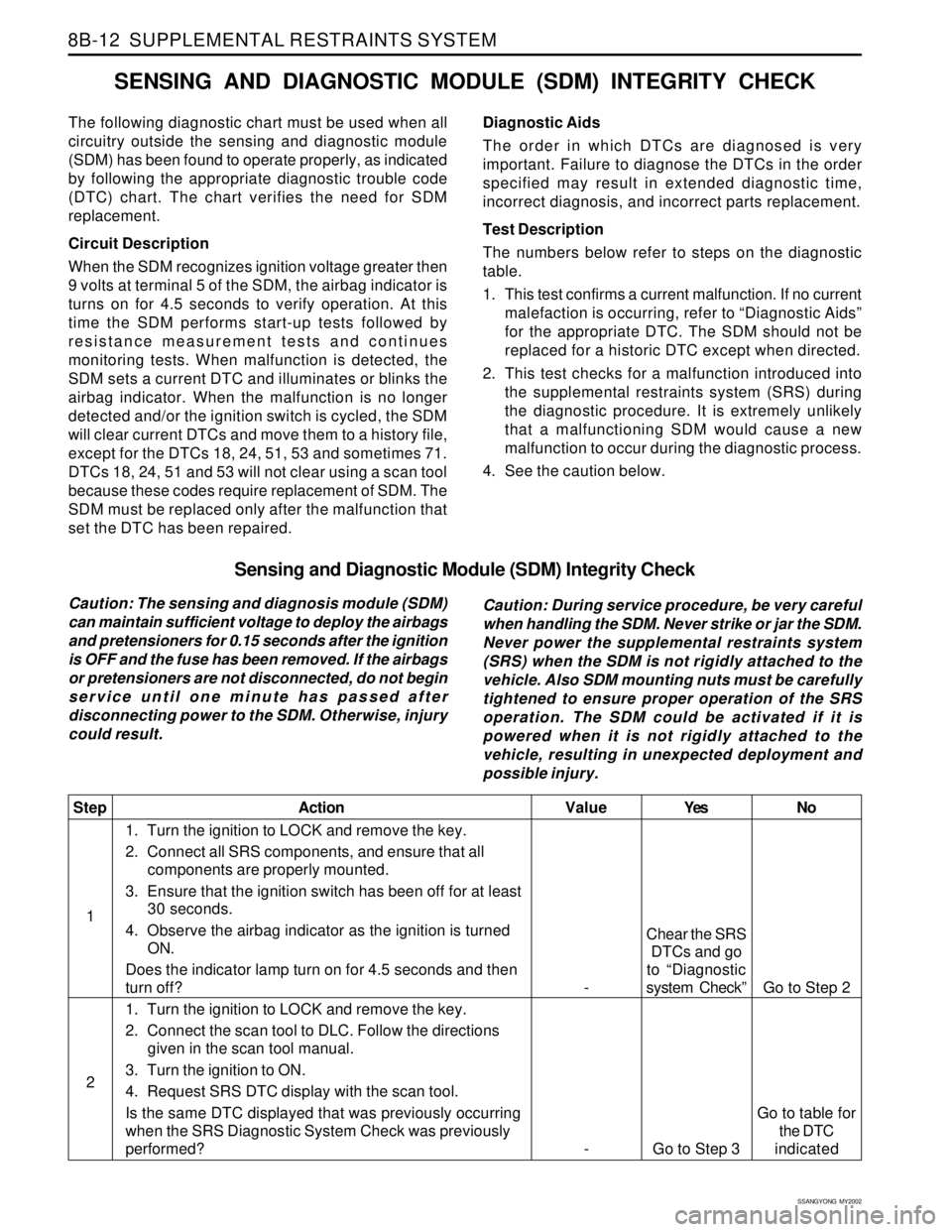
Sensing and Diagnostic Module (SDM) Integrity Check
Caution: The sensing and diagnosis module (SDM)
can maintain sufficient voltage to deploy the airbags
and pretensioners for 0.15 seconds after the ignition
is OFF and the fuse has been removed. If the airbags
or pretensioners are not disconnected, do not begin
service until one minute has passed after
disconnecting power to the SDM. Otherwise, injury
could result.Caution: During service procedure, be very careful
when handling the SDM. Never strike or jar the SDM.
Never power the supplemental restraints system
(SRS) when the SDM is not rigidly attached to the
vehicle. Also SDM mounting nuts must be carefully
tightened to ensure proper operation of the SRS
operation. The SDM could be activated if it is
powered when it is not rigidly attached to the
vehicle, resulting in unexpected deployment and
possible injury.
Yes
Chear the SRS
DTCs and go
to “Diagnostic
system Check”
Go to Step 3No
Go to Step 2
Go to table for
the DTC
indicated Value
-
-
Step
1
2Action
1. Turn the ignition to LOCK and remove the key.
2. Connect all SRS components, and ensure that all
components are properly mounted.
3. Ensure that the ignition switch has been off for at least
30 seconds.
4. Observe the airbag indicator as the ignition is turned
ON.
Does the indicator lamp turn on for 4.5 seconds and then
turn off?
1. Turn the ignition to LOCK and remove the key.
2. Connect the scan tool to DLC. Follow the directions
given in the scan tool manual.
3. Turn the ignition to ON.
4. Request SRS DTC display with the scan tool.
Is the same DTC displayed that was previously occurring
when the SRS Diagnostic System Check was previously
performed?
SENSING AND DIAGNOSTIC MODULE (SDM) INTEGRITY CHECK
The following diagnostic chart must be used when all
circuitry outside the sensing and diagnostic module
(SDM) has been found to operate properly, as indicated
by following the appropriate diagnostic trouble code
(DTC) chart. The chart verifies the need for SDM
replacement.
Circuit Description
When the SDM recognizes ignition voltage greater then
9 volts at terminal 5 of the SDM, the airbag indicator is
turns on for 4.5 seconds to verify operation. At this
time the SDM performs start-up tests followed by
resistance measurement tests and continues
monitoring tests. When malfunction is detected, the
SDM sets a current DTC and illuminates or blinks the
airbag indicator. When the malfunction is no longer
detected and/or the ignition switch is cycled, the SDM
will clear current DTCs and move them to a history file,
except for the DTCs 18, 24, 51, 53 and sometimes 71.
DTCs 18, 24, 51 and 53 will not clear using a scan tool
because these codes require replacement of SDM. The
SDM must be replaced only after the malfunction that
set the DTC has been repaired.Diagnostic Aids
The order in which DTCs are diagnosed is very
important. Failure to diagnose the DTCs in the order
specified may result in extended diagnostic time,
incorrect diagnosis, and incorrect parts replacement.
Test Description
The numbers below refer to steps on the diagnostic
table.
1. This test confirms a current malfunction. If no current
malefaction is occurring, refer to “Diagnostic Aids”
for the appropriate DTC. The SDM should not be
replaced for a historic DTC except when directed.
2. This test checks for a malfunction introduced into
the supplemental restraints system (SRS) during
the diagnostic procedure. It is extremely unlikely
that a malfunctioning SDM would cause a new
malfunction to occur during the diagnostic process.
4. See the caution below.
Page 1602 of 2053
SSANGYONG MY2002
8B-18 SUPPLEMENTAL RESTRAINTS SYSTEM
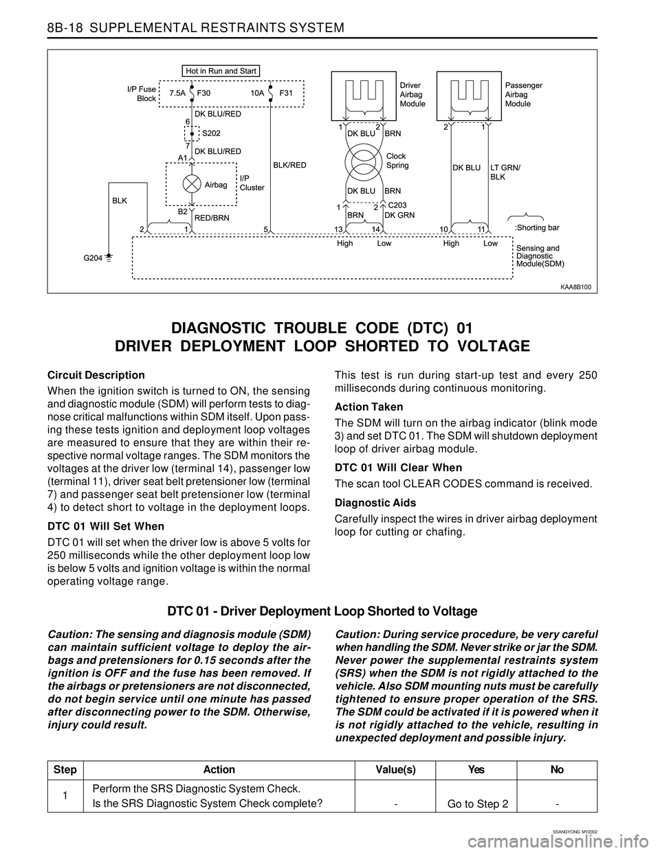
Circuit Description
When the ignition switch is turned to ON, the sensing
and diagnostic module (SDM) will perform tests to diag-
nose critical malfunctions within SDM itself. Upon pass-
ing these tests ignition and deployment loop voltages
are measured to ensure that they are within their re-
spective normal voltage ranges. The SDM monitors the
voltages at the driver low (terminal 14), passenger low
(terminal 11), driver seat belt pretensioner low (terminal
7) and passenger seat belt pretensioner low (terminal
4) to detect short to voltage in the deployment loops.
DTC 01 Will Set When
DTC 01 will set when the driver low is above 5 volts for
250 milliseconds while the other deployment loop low
is below 5 volts and ignition voltage is within the normal
operating voltage range.
DIAGNOSTIC TROUBLE CODE (DTC) 01
DRIVER DEPLOYMENT LOOP SHORTED TO VOLTAGE
This test is run during start-up test and every 250
milliseconds during continuous monitoring.
Action Taken
The SDM will turn on the airbag indicator (blink mode
3) and set DTC 01. The SDM will shutdown deployment
loop of driver airbag module.
DTC 01 Will Clear When
The scan tool CLEAR CODES command is received.
Diagnostic Aids
Carefully inspect the wires in driver airbag deployment
loop for cutting or chafing.
KAA8B100
DTC 01 - Driver Deployment Loop Shorted to Voltage
Caution: The sensing and diagnosis module (SDM)
can maintain sufficient voltage to deploy the air-
bags and pretensioners for 0.15 seconds after the
ignition is OFF and the fuse has been removed. If
the airbags or pretensioners are not disconnected,
do not begin service until one minute has passed
after disconnecting power to the SDM. Otherwise,
injury could result.Caution: During service procedure, be very careful
when handling the SDM. Never strike or jar the SDM.
Never power the supplemental restraints system
(SRS) when the SDM is not rigidly attached to the
vehicle. Also SDM mounting nuts must be carefully
tightened to ensure proper operation of the SRS.
The SDM could be activated if it is powered when it
is not rigidly attached to the vehicle, resulting in
unexpected deployment and possible injury.
Perform the SRS Diagnostic System Check.
Is the SRS Diagnostic System Check complete?
StepAction Value(s) Yes No
1-
Go to Step 2 -
Page 1604 of 2053
SSANGYONG MY2002
8B-20 SUPPLEMENTAL RESTRAINTS SYSTEM
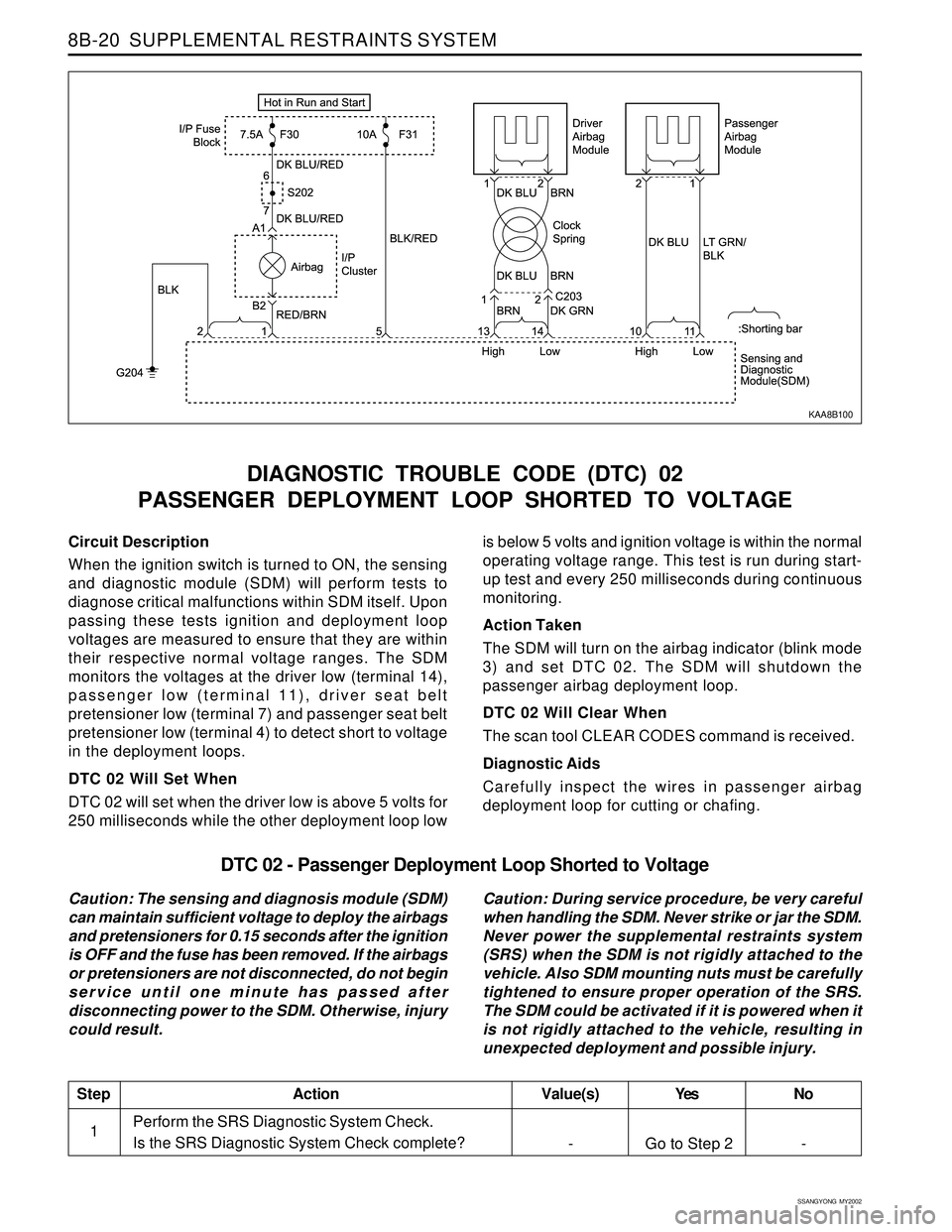
Circuit Description
When the ignition switch is turned to ON, the sensing
and diagnostic module (SDM) will perform tests to
diagnose critical malfunctions within SDM itself. Upon
passing these tests ignition and deployment loop
voltages are measured to ensure that they are within
their respective normal voltage ranges. The SDM
monitors the voltages at the driver low (terminal 14),
passenger low (terminal 11), driver seat belt
pretensioner low (terminal 7) and passenger seat belt
pretensioner low (terminal 4) to detect short to voltage
in the deployment loops.
DTC 02 Will Set When
DTC 02 will set when the driver low is above 5 volts for
250 milliseconds while the other deployment loop low
DIAGNOSTIC TROUBLE CODE (DTC) 02
PASSENGER DEPLOYMENT LOOP SHORTED TO VOLTAGE
is below 5 volts and ignition voltage is within the normal
operating voltage range. This test is run during start-
up test and every 250 milliseconds during continuous
monitoring.
Action Taken
The SDM will turn on the airbag indicator (blink mode
3) and set DTC 02. The SDM will shutdown the
passenger airbag deployment loop.
DTC 02 Will Clear When
The scan tool CLEAR CODES command is received.
Diagnostic Aids
Carefully inspect the wires in passenger airbag
deployment loop for cutting or chafing.
KAA8B100
DTC 02 - Passenger Deployment Loop Shorted to Voltage
Caution: The sensing and diagnosis module (SDM)
can maintain sufficient voltage to deploy the airbags
and pretensioners for 0.15 seconds after the ignition
is OFF and the fuse has been removed. If the airbags
or pretensioners are not disconnected, do not begin
service until one minute has passed after
disconnecting power to the SDM. Otherwise, injury
could result.Caution: During service procedure, be very careful
when handling the SDM. Never strike or jar the SDM.
Never power the supplemental restraints system
(SRS) when the SDM is not rigidly attached to the
vehicle. Also SDM mounting nuts must be carefully
tightened to ensure proper operation of the SRS.
The SDM could be activated if it is powered when it
is not rigidly attached to the vehicle, resulting in
unexpected deployment and possible injury.
Perform the SRS Diagnostic System Check.
Is the SRS Diagnostic System Check complete?
StepAction Value(s) Yes No
1- Go to Step 2 -