Page 924 of 2053
SSAMGYONG MY2002
4A-4 HYDRAULIC BRAKES
KAA4A010
BRAKE WARNING LAMP CIRCUIT DESCRIPTION
Diagnostic Aids
The BRAKE lamp glows brightly when the ignition is
ON and either the parking brake lever switch or the
brake fluid level switch is closed.
If neither switch is closed, the BRAKE lamp receives
a ground through the generator, and it glows dimly
when the ignition is ON and the engine is off. When
the engine starts, the generator creates voltage. With
voltage on both sides of the lamp, the lamp turns off.
Test Description
The numbers below refer to steps in the diagnostic
table.
1. This step begins the test sequence for a BRAKE
warning lamp that stays on when the engine is run-
ning.
2. This step begins the test sequence for a BRAKE
warning lamp that never turns on.
Page 925 of 2053

HYDRAULIC BRAKES 4A-5
SSANGYONG MY2002
Value(s)
-
-
-
-
-
-
-
-
-
-
-
-
-
-
BRAKE WARNING LAMP DIAGNOSIS
Step
1
2
3
4
5
6
7
8
9
10
11
12
13
14Action
Start the engine and leave it running.
Does the BRAKE warning lamp stay on?
With the engine running, release the parking brake.
Is the BRAKE warning lamp off?
Check the brake fluid level.
Is the fluid level OK?
1. Fill the brake fluid reservoir with clean DOT-3
hydraulic fluid.
2. Check the cap on the fluid reservoir.
3. Start the engine and leave it running.
Is the BRAKE warning lamp on?
Disconnect the wiring harness connector from the
brake fluid level switch.
Is the BRAKE warning lamp on?
Replace the brake fluid lever switch.
Is the repair complete?
1. Connect the brake fluid level switch.
2. Disconnect the parking brake lever switch.
3. Start the engine and leave it running.
Is the BRAKE warning lamp on?
Replace the parking brake lever switch.
Is the repair complete?
1. Connect the parking brake lever switch.
2. Disconnect the STICS (Super Time and Alarm
Integrated System).
3. Start the engine and leave it running.
Is the BRAKE warning lamp on?
Replace the STICS.
Is the repair complete?
Repair the short circuit in the instrument wiring
harness between terminal D10 of the instrument
cluster and ground.
Is the repair complete?
1. Disconnect the electrical connector from the fluid
level switch.
2. Connect a jumper wire between ground and
terminal 1 of the fluid level switch harness
connector.
Does the BRAKE warning lamp turn on?
1. Disconnect the electrical connector from the fluid
level switch.
2. Connect a jump wire between terminals 1 and 2
of the fluid level switch harness connector.
Does the BRAKE warning lamp turn on?
1. Replace the brake fluid level switch.
2 The switch can be removed and replaced without
draining the brake fluid from the reservoir.
Is the repair complete?Yes
Go To Step 2
System OK
Go To Step 5
Go To Step 5
Go To Step 7
System OK
Go To Step 9
System OK
Go To Step 11
System OK
System OK
Go To Step 13
Go To Step 14
System OKNO
Go To Step 12
Go To Step 3
Go To Step 4
System OK
Go To Step 6
-
Go To Step 8
-
Go To Step 10
-
-
Go To Step 15
Go To Step 15
-
Page 998 of 2053

ABS AND TCS 4F-15
SSANGYONG MY2002
DIAGNOSIS
KAA4F110
DIAGNOSTIC CIRCUIT CHECK
The Diagnostic Circuit Check is an organized approach
to identifying a problem created by an antilock brake
system (ABS) malfunction. If must be the starting point
for any ABS complaint diagnosis because it directs
the service technician to the next logical step in
diagnosing the complaint.
Diagnostic Process
Perform the following steps in order when servicing
the ABS/TCS system. Failure to do so may result in
the loss of important diagnostic data and may lead to
difficulties and time-consuming diagnosis procedures.
1. Perform the tests of the table below.2. Perform a road test if directed by the table.
Test drive the vehicle while using the snapshot
feature of the scan tool.
Perform normal acceleration, stopping, and
turning maneuvers.
If this does not reproduce the malfunction,
perform an ABS stop or TCS maneuver on a low
friction surface such as gravel.
3. Clear the diagnostic trouble codes (DTCs) after
all system malfunctions have been corrected.
Page 1001 of 2053

SSANGYONG MY2002
4F-18 ABS AND TCS
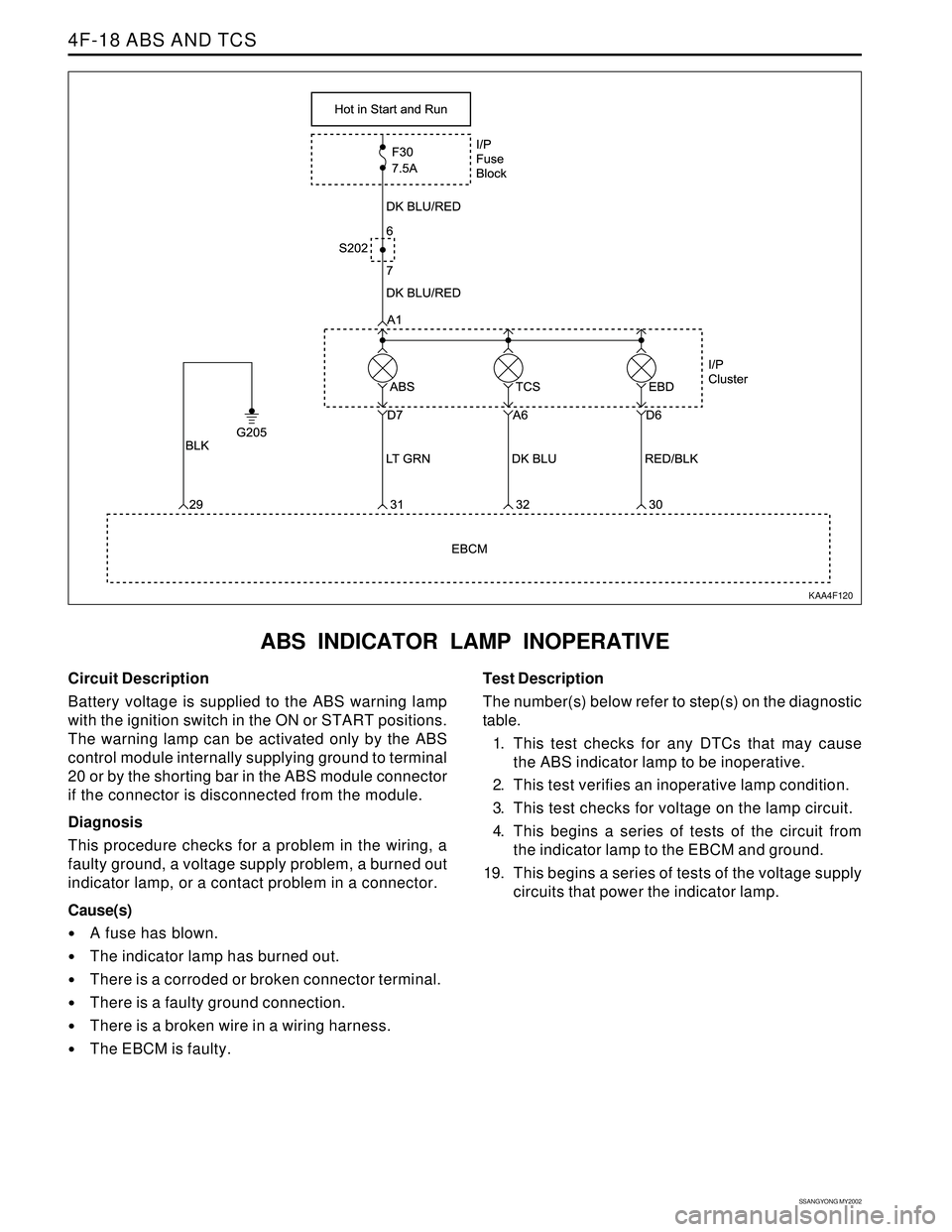
ABS INDICATOR LAMP INOPERATIVE
KAA4F120
Circuit Description
Battery voltage is supplied to the ABS warning lamp
with the ignition switch in the ON or START positions.
The warning lamp can be activated only by the ABS
control module internally supplying ground to terminal
20 or by the shorting bar in the ABS module connector
if the connector is disconnected from the module.
Diagnosis
This procedure checks for a problem in the wiring, a
faulty ground, a voltage supply problem, a burned out
indicator lamp, or a contact problem in a connector.
Cause(s)
A fuse has blown.
The indicator lamp has burned out.
There is a corroded or broken connector terminal.
There is a faulty ground connection.
There is a broken wire in a wiring harness.
The EBCM is faulty.Test Description
The number(s) below refer to step(s) on the diagnostic
table.
1. This test checks for any DTCs that may cause
the ABS indicator lamp to be inoperative.
2. This test verifies an inoperative lamp condition.
3. This test checks for voltage on the lamp circuit.
4. This begins a series of tests of the circuit from
the indicator lamp to the EBCM and ground.
19. This begins a series of tests of the voltage supply
circuits that power the indicator lamp.
Page 1005 of 2053

SSANGYONG MY2002
4F-22 ABS AND TCS
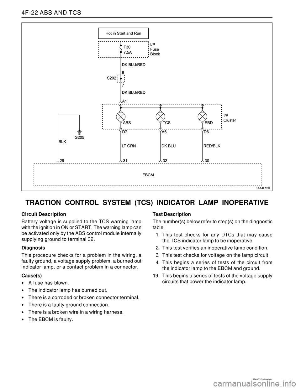
TRACTION CONTROL SYSTEM (TCS) INDICATOR LAMP INOPERATIVE
KAA4F120
Circuit Description
Battery voltage is supplied to the TCS warning lamp
with the ignition in ON or START. The warning lamp can
be activated only by the ABS control module internally
supplying ground to terminal 32.
Diagnosis
This procedure checks for a problem in the wiring, a
faulty ground, a voltage supply problem, a burned out
indicator lamp, or a contact problem in a connector.
Cause(s)
A fuse has blown.
The indicator lamp has burned out.
There is a corroded or broken connector terminal.
There is a faulty ground connection.
There is a broken wire in a wiring harness.
The EBCM is faulty.Test Description
The number(s) below refer to step(s) on the diagnostic
table.
1. This test checks for any DTCs that may cause
the TCS indicator lamp to be inoperative.
2. This test verifies an inoperative lamp condition.
3. This test checks for voltage on the lamp circuit.
4. This begins a series of tests of the circuit from
the indicator lamp to the EBCM and ground.
19. This begins a series of tests of the voltage supply
circuits that power the indicator lamp.
Page 1009 of 2053

SSANGYONG MY2002
4F-26 ABS AND TCS
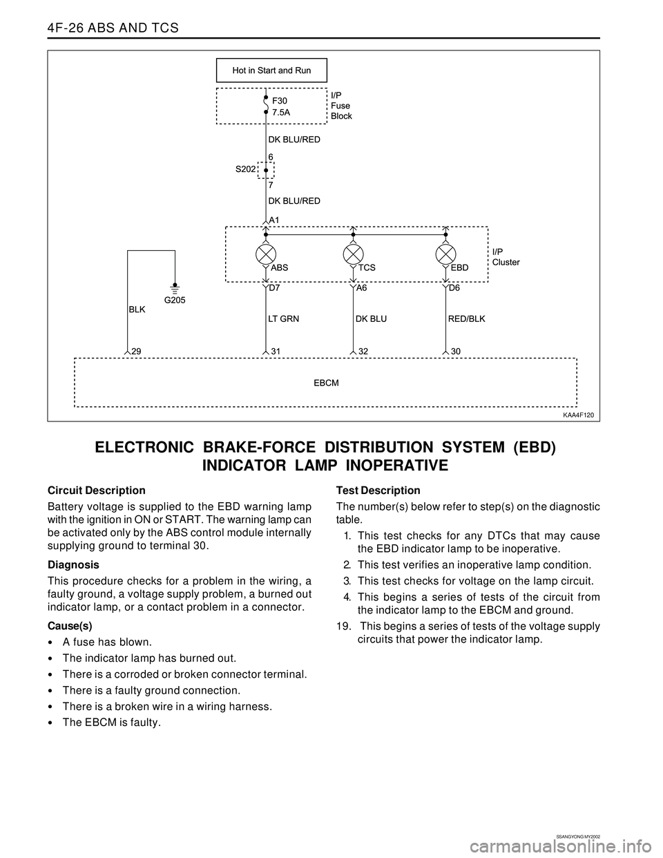
ELECTRONIC BRAKE-FORCE DISTRIBUTION SYSTEM (EBD)
INDICATOR LAMP INOPERATIVE
KAA4F120
Circuit Description
Battery voltage is supplied to the EBD warning lamp
with the ignition in ON or START. The warning lamp can
be activated only by the ABS control module internally
supplying ground to terminal 30.
Diagnosis
This procedure checks for a problem in the wiring, a
faulty ground, a voltage supply problem, a burned out
indicator lamp, or a contact problem in a connector.
Cause(s)
A fuse has blown.
The indicator lamp has burned out.
There is a corroded or broken connector terminal.
There is a faulty ground connection.
There is a broken wire in a wiring harness.
The EBCM is faulty.Test Description
The number(s) below refer to step(s) on the diagnostic
table.
1. This test checks for any DTCs that may cause
the EBD indicator lamp to be inoperative.
2. This test verifies an inoperative lamp condition.
3. This test checks for voltage on the lamp circuit.
4. This begins a series of tests of the circuit from
the indicator lamp to the EBCM and ground.
19. This begins a series of tests of the voltage supply
circuits that power the indicator lamp.
Page 1013 of 2053

SSANGYONG MY2002
4F-30 ABS AND TCS
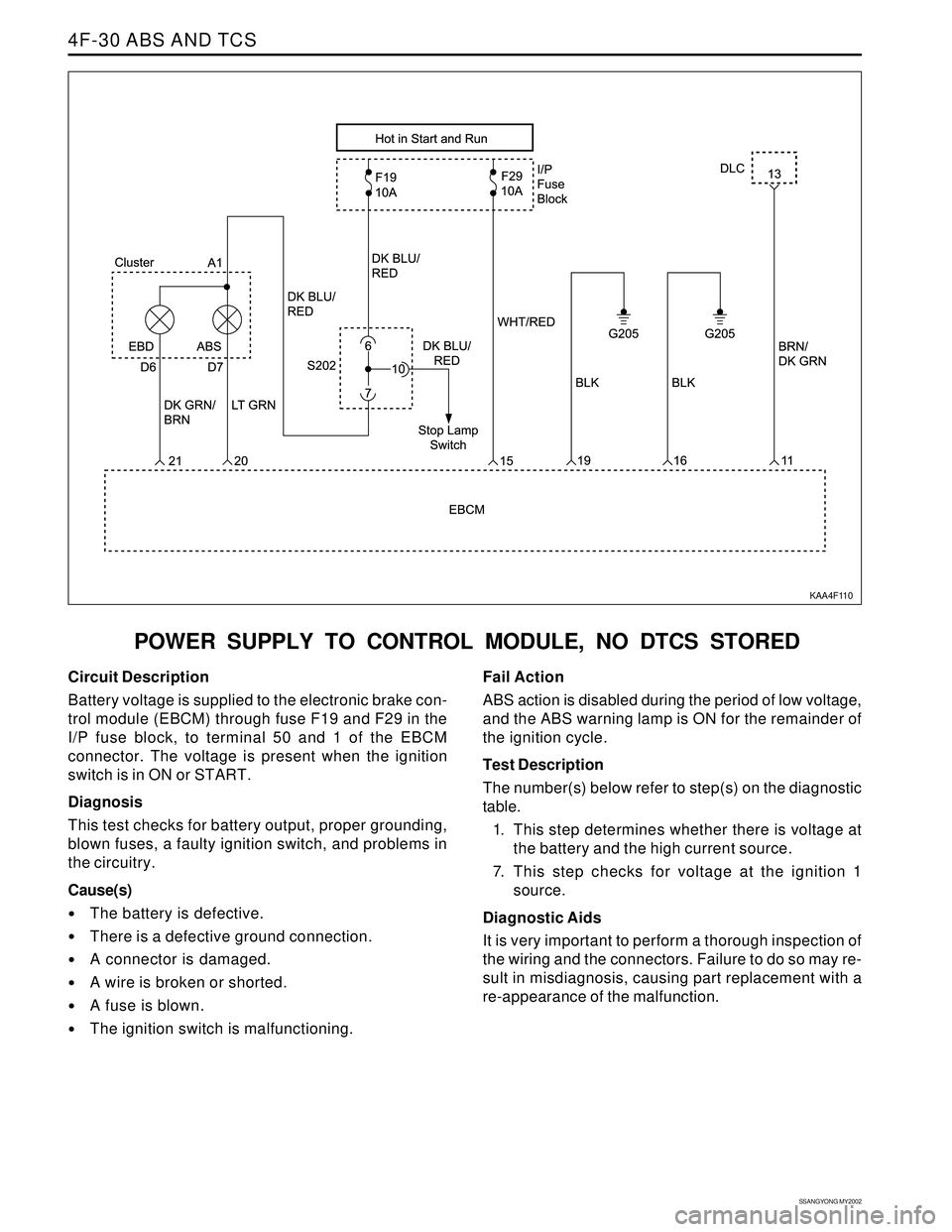
POWER SUPPLY TO CONTROL MODULE, NO DTCS STORED
KAA4F110
Circuit Description
Battery voltage is supplied to the electronic brake con-
trol module (EBCM) through fuse F19 and F29 in the
I/P fuse block, to terminal 50 and 1 of the EBCM
connector. The voltage is present when the ignition
switch is in ON or START.
Diagnosis
This test checks for battery output, proper grounding,
blown fuses, a faulty ignition switch, and problems in
the circuitry.
Cause(s)
The battery is defective.
There is a defective ground connection.
A connector is damaged.
A wire is broken or shorted.
A fuse is blown.
The ignition switch is malfunctioning.Fail Action
ABS action is disabled during the period of low voltage,
and the ABS warning lamp is ON for the remainder of
the ignition cycle.
Test Description
The number(s) below refer to step(s) on the diagnostic
table.
1. This step determines whether there is voltage at
the battery and the high current source.
7. This step checks for voltage at the ignition 1
source.
Diagnostic Aids
It is very important to perform a thorough inspection of
the wiring and the connectors. Failure to do so may re-
sult in misdiagnosis, causing part replacement with a
re-appearance of the malfunction.
Page 1017 of 2053
SSANGYONG MY2002
4F-34 ABS AND TCS
ABS INDICATOR LAMP ILLUMINATED CONTINUOUSLY,
NO DTCS STORED
KAA4F120
Circuit Description
Battery voltage is supplied to the ABS warning lamp
with the ignition in ON or START. The warning lamp
should be activated only by the ABS control module
internally supplying ground to terminal 31.
Diagnosis
This procedure checks for a short to ground in the
wiring or a defective electronic brake control module
(EBCM).Cause(s)
There is a short to ground in the circuit between the
cluster terminal D7 and the EBCM terminal 31.
The EBCM is faulty.