1997 SSANGYONG KORANDO oil
[x] Cancel search: oilPage 989 of 2053

ABS AND TCS 4F-5
SSANGYONG MY2002
EBD (ELECTRONIC BRAKE
FORCE DISTRIBUTION) SYSTEM
System Description
As an add-on logic to the ABS base algorithm, EBD
works in a range in which the intervention thresholds
for ABS control are not reached yet.
EBD ensures that the rear wheels are sensitively
monitored for slip with respect to the front axle. If slip
is detected, the inlet valves for the rear wheels are
switched to pressure hold to prevent a further increase
in pressure at the rear-wheel breaks, thus electronically
reproducing a pressure-reduction function at the rear-
wheel brakes.
ABS features an enhanced algorithm which includes
control of the brake force distribution between the front
and rear axles. This is called Electronic Brake
Distribution. In an unloading car condition the brake
efficiency is comparable to the conventional system
but for a fully loaden vehicle the efficiency of the EBD
system is higher due to the better use of rear axle
braking capability.
The Benefits of EBD
Elimination of conventional proportioning valve EBD
utilizes the existing rear axle wheel speed sensor
to monitor rear wheel slip.
Based on many variables in algorithm a pressure
hold, increase and/or decrease pulsetrain may be
triggered at the rear wheels insuring vehicle
stability.
Vehicle approaches the ideal brake force
distribution (front to rear).
Constant brake force distribution during vehicle
lifetime.
EBD function is monitored via ABS safety logic
(conventional proportioning valves are not
monitorable).
“Keep alive” function.Service Precautions
Observe the following general precautions during any
ABS/TCS service. Failure to adhere to these
precautions may result in ABS/TCS system damage.
1. Disconnect the EBCM harness connector before
performing the electric welding procedures.
2. Carefully note the routing of the ABS/TCS wiring
and wring components during removal. The ABS/
TCS components are extremely sensitive to EMI
(eletromagnetic interference). Proper mounting is
critical during component service.
3. Disconnect the EBCM connector with the ignition
OFF.
4. Do not hang the suspension components from the
wheel speed sensor cables. The cables may be
damaged.
5. Do not use petroleum based fluids in the master
cylinder. Do not use any containers previously used
for petroleum based fluids. Petroleum causes
swelling and distortion of the rubber components
in the hydraulic brake system, resulting in water
entering the system and lowering the fluid boiling
point.
KAA4F020
Page 1002 of 2053
ABS AND TCS 4F-19
SSANGYONG MY2002
Step
1
2
3
4
5
6
7
8
9
10
11
12
13
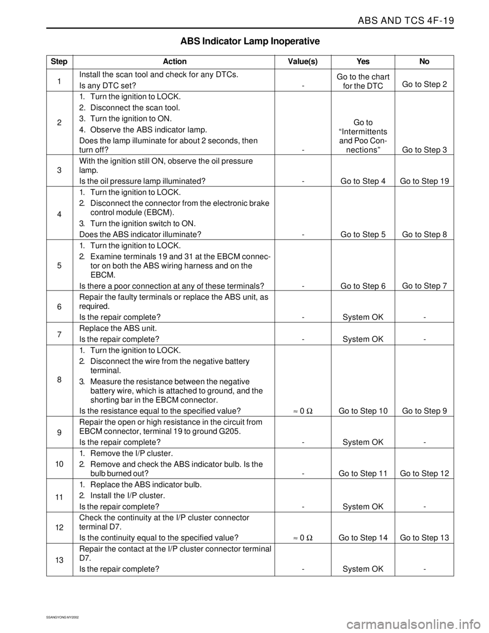
ABS Indicator Lamp Inoperative
Action Yes
Go to the chart
for the DTC
Go to
“Intermittents
and Poo Con-
nections”
Go to Step 4
Go to Step 5
Go to Step 6
System OK
System OK
Go to Step 10
System OK
Go to Step 11
System OK
Go to Step 14
System OKNo
Go to Step 2
Go to Step 3
Go to Step 19
Go to Step 8
Go to Step 7
-
-
Go to Step 9
-
Go to Step 12
-
Go to Step 13
- Value(s)
Install the scan tool and check for any DTCs.
Is any DTC set?
1. Turn the ignition to LOCK.
2. Disconnect the scan tool.
3. Turn the ignition to ON.
4. Observe the ABS indicator lamp.
Does the lamp illuminate for about 2 seconds, then
turn off?
With the ignition still ON, observe the oil pressure
lamp.
Is the oil pressure lamp illuminated?
1. Turn the ignition to LOCK.
2. Disconnect the connector from the electronic brake
control module (EBCM).
3. Turn the ignition switch to ON.
Does the ABS indicator illuminate?
1. Turn the ignition to LOCK.
2. Examine terminals 19 and 31 at the EBCM connec-
tor on both the ABS wiring harness and on the
EBCM.
Is there a poor connection at any of these terminals?
Repair the faulty terminals or replace the ABS unit, as
required.
Is the repair complete?
Replace the ABS unit.
Is the repair complete?
1. Turn the ignition to LOCK.
2. Disconnect the wire from the negative battery
terminal.
3. Measure the resistance between the negative
battery wire, which is attached to ground, and the
shorting bar in the EBCM connector.
Is the resistance equal to the specified value?
Repair the open or high resistance in the circuit from
EBCM connector, terminal 19 to ground G205.
Is the repair complete?
1. Remove the I/P cluster.
2. Remove and check the ABS indicator bulb. Is the
bulb burned out?
1. Replace the ABS indicator bulb.
2. Install the I/P cluster.
Is the repair complete?
Check the continuity at the I/P cluster connector
terminal D7.
Is the continuity equal to the specified value?
Repair the contact at the I/P cluster connector terminal
D7.
Is the repair complete?
-
-
-
-
-
-
-
≈ 0 Ω
-
-
-
≈ 0 Ω
-
Page 1006 of 2053
ABS AND TCS 4F-23
SSANGYONG MY2002
Step
1
2
3
4
5
6
7
8
9
10
11
12
13
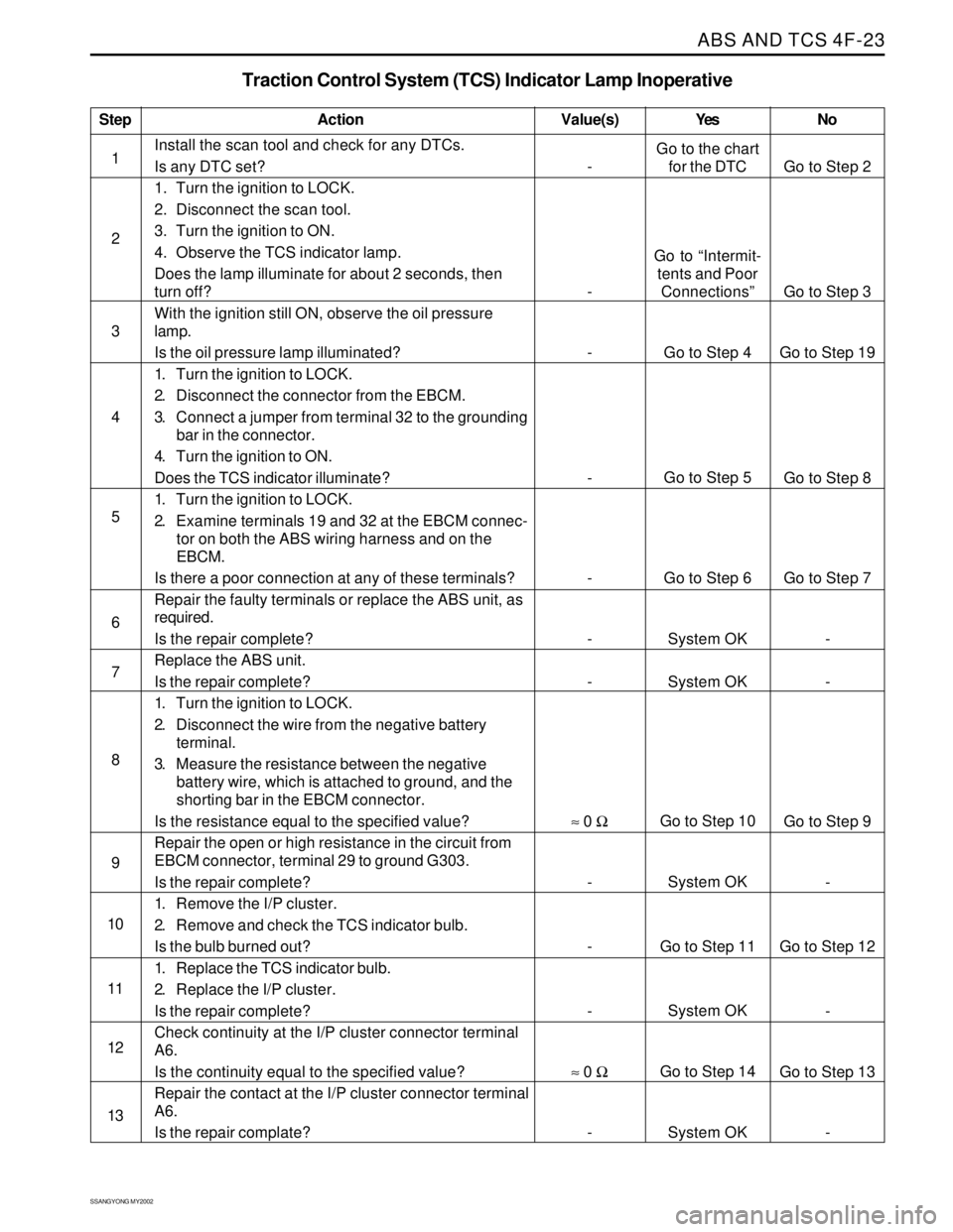
Traction Control System (TCS) Indicator Lamp Inoperative
Action Yes NoValue(s)
Install the scan tool and check for any DTCs.
Is any DTC set?
1. Turn the ignition to LOCK.
2. Disconnect the scan tool.
3. Turn the ignition to ON.
4. Observe the TCS indicator lamp.
Does the lamp illuminate for about 2 seconds, then
turn off?
With the ignition still ON, observe the oil pressure
lamp.
Is the oil pressure lamp illuminated?
1. Turn the ignition to LOCK.
2. Disconnect the connector from the EBCM.
3. Connect a jumper from terminal 32 to the grounding
bar in the connector.
4. Turn the ignition to ON.
Does the TCS indicator illuminate?
1. Turn the ignition to LOCK.
2. Examine terminals 19 and 32 at the EBCM connec-
tor on both the ABS wiring harness and on the
EBCM.
Is there a poor connection at any of these terminals?
Repair the faulty terminals or replace the ABS unit, as
required.
Is the repair complete?
Replace the ABS unit.
Is the repair complete?
1. Turn the ignition to LOCK.
2. Disconnect the wire from the negative battery
terminal.
3. Measure the resistance between the negative
battery wire, which is attached to ground, and the
shorting bar in the EBCM connector.
Is the resistance equal to the specified value?
Repair the open or high resistance in the circuit from
EBCM connector, terminal 29 to ground G303.
Is the repair complete?
1. Remove the I/P cluster.
2. Remove and check the TCS indicator bulb.
Is the bulb burned out?
1. Replace the TCS indicator bulb.
2. Replace the I/P cluster.
Is the repair complete?
Check continuity at the I/P cluster connector terminal
A6.
Is the continuity equal to the specified value?
Repair the contact at the I/P cluster connector terminal
A6.
Is the repair complate?
-
-
-
-
-
-
-
≈ 0 Ω
-
-
-
≈ 0 Ω
-Go to the chart
for the DTC
Go to “Intermit-
tents and Poor
Connections”
Go to Step 4
Go to Step 5
Go to Step 6
System OK
System OK
Go to Step 10
System OK
Go to Step 11
System OK
Go to Step 14
System OKGo to Step 2
Go to Step 3
Go to Step 19
Go to Step 8
Go to Step 7
-
-
Go to Step 9
-
Go to Step 12
-
Go to Step 13
-
Page 1010 of 2053
ABS AND TCS 4F-27
SSANGYONG MY2002
Step
1
2
3
4
5
6
7
8
9
10
11
12
13
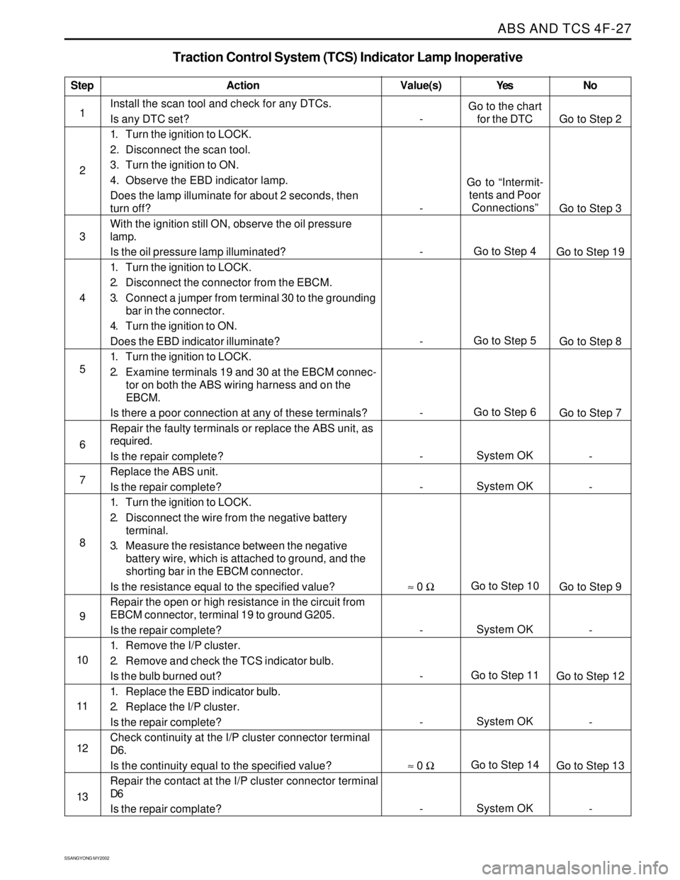
Traction Control System (TCS) Indicator Lamp Inoperative
Action
Go to the chart
for the DTC
Go to “Intermit-
tents and Poor
Connections”
Go to Step 4
Go to Step 5
Go to Step 6
System OK
System OK
Go to Step 10
System OK
Go to Step 11
System OK
Go to Step 14
System OKGo to Step 2
Go to Step 3
Go to Step 19
Go to Step 8
Go to Step 7
-
-
Go to Step 9
-
Go to Step 12
-
Go to Step 13
- Value(s)
Install the scan tool and check for any DTCs.
Is any DTC set?
1. Turn the ignition to LOCK.
2. Disconnect the scan tool.
3. Turn the ignition to ON.
4. Observe the EBD indicator lamp.
Does the lamp illuminate for about 2 seconds, then
turn off?
With the ignition still ON, observe the oil pressure
lamp.
Is the oil pressure lamp illuminated?
1. Turn the ignition to LOCK.
2. Disconnect the connector from the EBCM.
3. Connect a jumper from terminal 30 to the grounding
bar in the connector.
4. Turn the ignition to ON.
Does the EBD indicator illuminate?
1. Turn the ignition to LOCK.
2. Examine terminals 19 and 30 at the EBCM connec-
tor on both the ABS wiring harness and on the
EBCM.
Is there a poor connection at any of these terminals?
Repair the faulty terminals or replace the ABS unit, as
required.
Is the repair complete?
Replace the ABS unit.
Is the repair complete?
1. Turn the ignition to LOCK.
2. Disconnect the wire from the negative battery
terminal.
3. Measure the resistance between the negative
battery wire, which is attached to ground, and the
shorting bar in the EBCM connector.
Is the resistance equal to the specified value?
Repair the open or high resistance in the circuit from
EBCM connector, terminal 19 to ground G205.
Is the repair complete?
1. Remove the I/P cluster.
2. Remove and check the TCS indicator bulb.
Is the bulb burned out?
1. Replace the EBD indicator bulb.
2. Replace the I/P cluster.
Is the repair complete?
Check continuity at the I/P cluster connector terminal
D6.
Is the continuity equal to the specified value?
Repair the contact at the I/P cluster connector terminal
D6
Is the repair complate?
-
-
-
-
-
-
-
≈ 0 Ω
-
-
-
≈ 0 Ω
-Yes No
Page 1045 of 2053
SSANGYONG MY2002
4F-62 ABS AND TCS
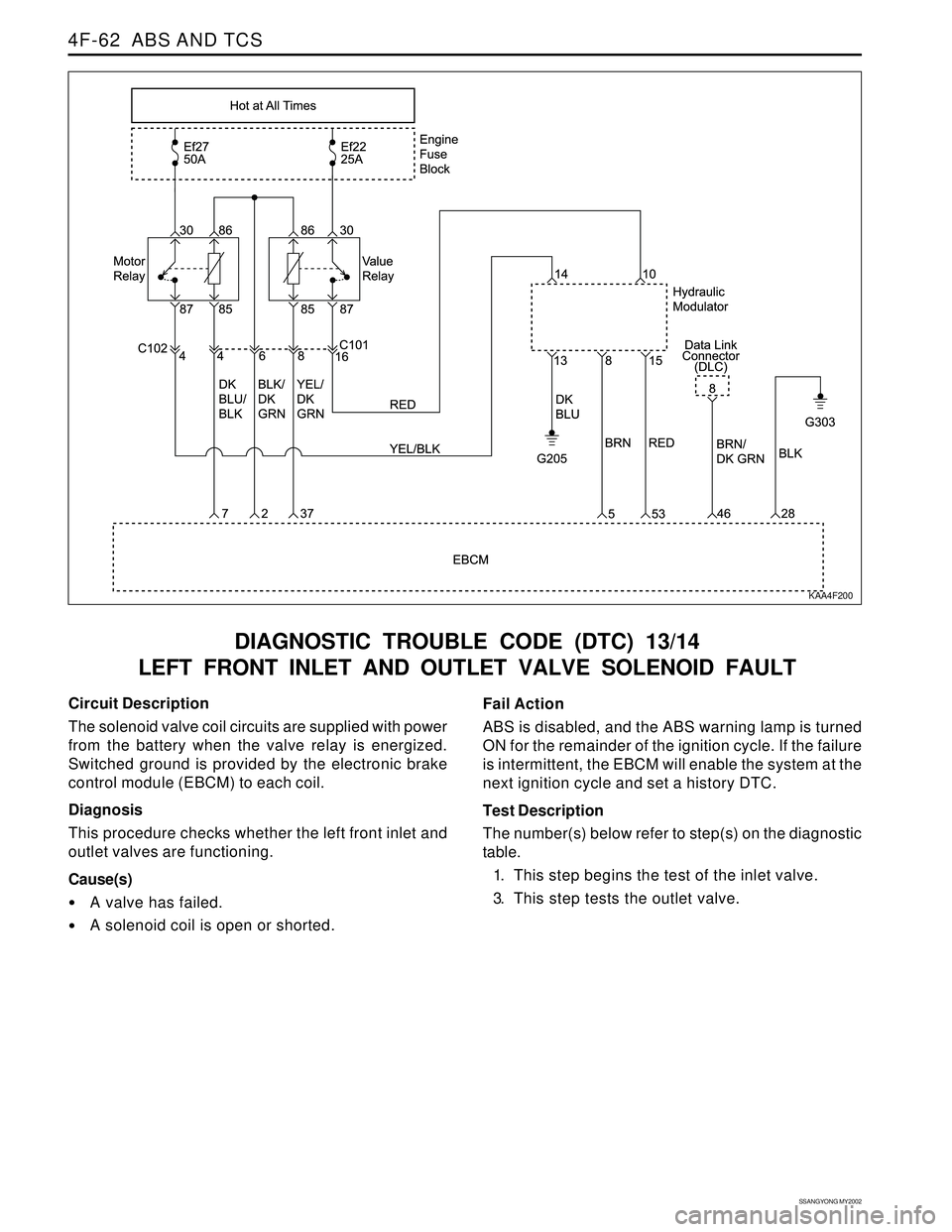
DIAGNOSTIC TROUBLE CODE (DTC) 13/14
LEFT FRONT INLET AND OUTLET VALVE SOLENOID FAULT
KAA4F200
Circuit Description
The solenoid valve coil circuits are supplied with power
from the battery when the valve relay is energized.
Switched ground is provided by the electronic brake
control module (EBCM) to each coil.
Diagnosis
This procedure checks whether the left front inlet and
outlet valves are functioning.
Cause(s)
A valve has failed.
A solenoid coil is open or shorted.Fail Action
ABS is disabled, and the ABS warning lamp is turned
ON for the remainder of the ignition cycle. If the failure
is intermittent, the EBCM will enable the system at the
next ignition cycle and set a history DTC.
Test Description
The number(s) below refer to step(s) on the diagnostic
table.
1. This step begins the test of the inlet valve.
3. This step tests the outlet valve.
Page 1047 of 2053
SSANGYONG MY2002
4F-64 ABS AND TCS
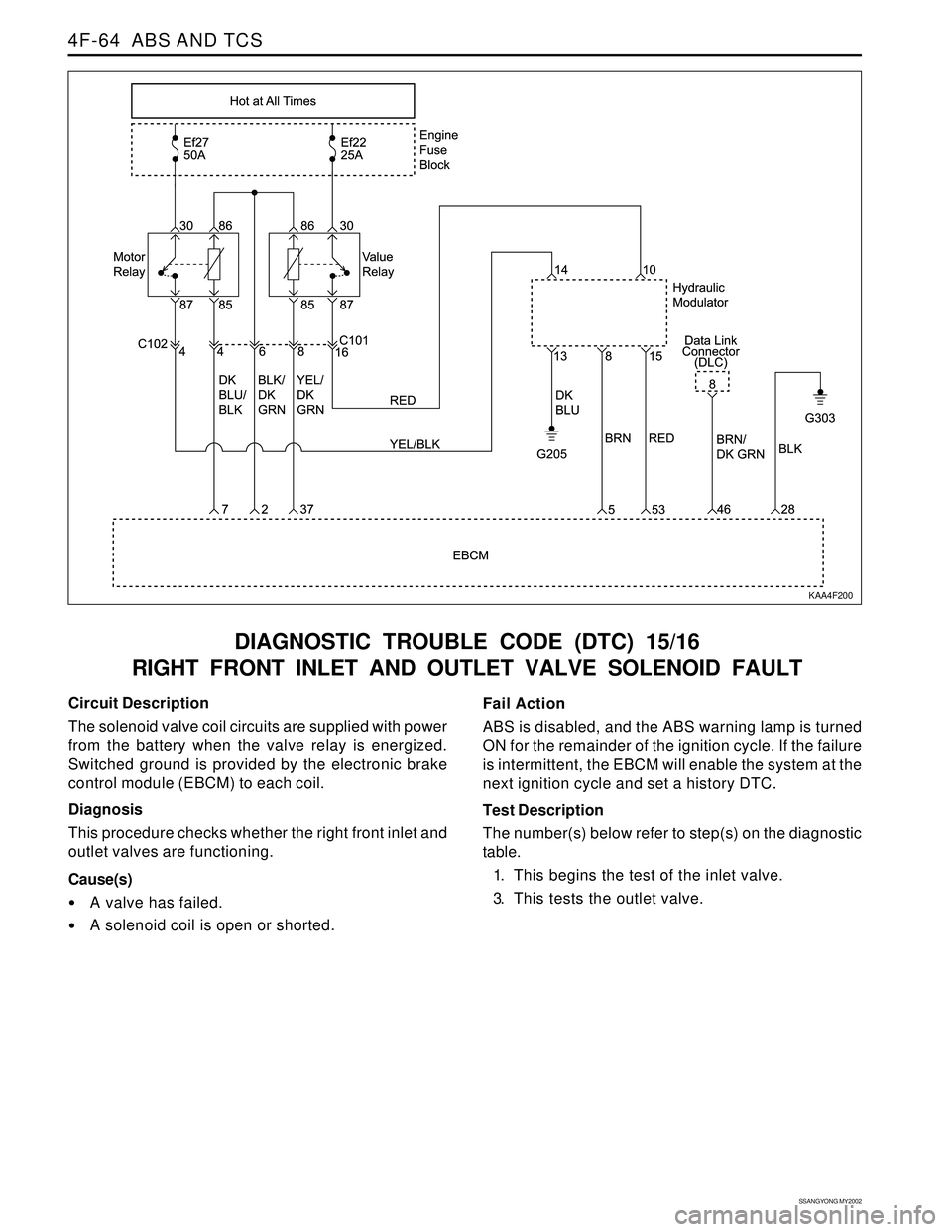
DIAGNOSTIC TROUBLE CODE (DTC) 15/16
RIGHT FRONT INLET AND OUTLET VALVE SOLENOID FAULT
KAA4F200
Circuit Description
The solenoid valve coil circuits are supplied with power
from the battery when the valve relay is energized.
Switched ground is provided by the electronic brake
control module (EBCM) to each coil.
Diagnosis
This procedure checks whether the right front inlet and
outlet valves are functioning.
Cause(s)
A valve has failed.
A solenoid coil is open or shorted.Fail Action
ABS is disabled, and the ABS warning lamp is turned
ON for the remainder of the ignition cycle. If the failure
is intermittent, the EBCM will enable the system at the
next ignition cycle and set a history DTC.
Test Description
The number(s) below refer to step(s) on the diagnostic
table.
1. This begins the test of the inlet valve.
3. This tests the outlet valve.
Page 1049 of 2053
SSANGYONG MY2002
4F-66 ABS AND TCS
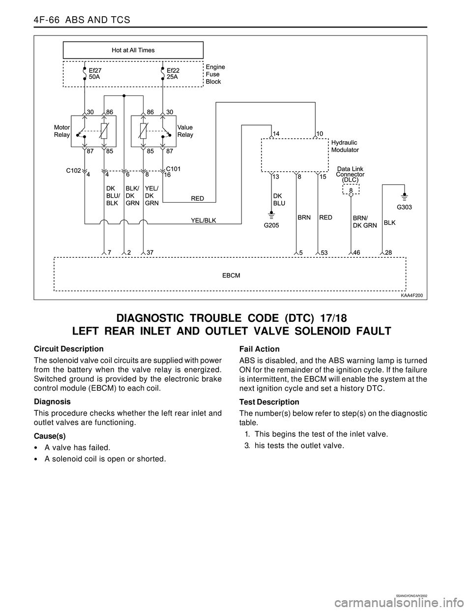
DIAGNOSTIC TROUBLE CODE (DTC) 17/18
LEFT REAR INLET AND OUTLET VALVE SOLENOID FAULT
KAA4F200
Circuit Description
The solenoid valve coil circuits are supplied with power
from the battery when the valve relay is energized.
Switched ground is provided by the electronic brake
control module (EBCM) to each coil.
Diagnosis
This procedure checks whether the left rear inlet and
outlet valves are functioning.
Cause(s)
A valve has failed.
A solenoid coil is open or shorted.Fail Action
ABS is disabled, and the ABS warning lamp is turned
ON for the remainder of the ignition cycle. If the failure
is intermittent, the EBCM will enable the system at the
next ignition cycle and set a history DTC.
Test Description
The number(s) below refer to step(s) on the diagnostic
table.
1. This begins the test of the inlet valve.
3. his tests the outlet valve.
Page 1051 of 2053
SSANGYONG MY2002
4F-68 ABS AND TCS
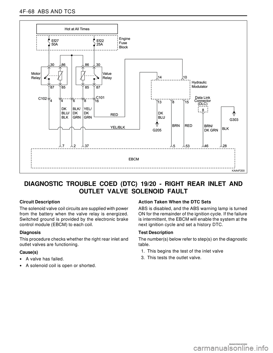
DIAGNOSTIC TROUBLE COED (DTC) 19/20 - RIGHT REAR INLET AND
OUTLET VALVE SOLENOID FAULT
Circuit Description
The solenoid valve coil circuits are supplied with power
from the battery when the valve relay is energized.
Switched ground is provided by the electronic brake
control module (EBCM) to each coil.
Diagnosis
This procedure checks whether the right rear inlet and
outlet valves are functioning.
Cause(s)
A valve has failed.
A solenoid coil is open or shorted.Action Taken When the DTC Sets
ABS is disabled, and the ABS warning lamp is turned
ON for the remainder of the ignition cycle. If the failure
is intermittent, the EBCM will enable the system at the
next ignition cycle and set a history DTC.
Test Description
The number(s) below refer to step(s) on the diagnostic
table.
1. This begins the test of the inlet valve
3. This tests the outlet valve.
KAA4F200