Page 565 of 2053
1B3 -- 16 OM600 ENGINE MECHANICAL
D AEW OO M Y_2000
16. Remove the power steering pump lines.
Notice
Completely drain the fluid.
17. Disconnect the fuel feed line with prefilter from the
feed pump on injection pump.
18. Vehicle with automatic transmission.
Remove the hydraulic lines (19, 20) from oil cooler
(2).
19. Disconnect the engine harness.
20. Disconnect the preheating time relay cable.
Page 814 of 2053

SSANGYONG MY2002
2A-2 SUSPENSION DIAGNOSIS
Inspect the tires for improper pressure and uneven wear.
Inspect the joint from the steering column to the steer-
ing gear for loose connections or wear.
Inspect the front and the rear suspension, the steering
gear, and the linkage for loose or damaged parts.
Inspect for out-of-round tires.
Inspect for out-of-balance tires, bent wheels, and worn
or loose wheel bearings.
Check the power steering pump serpentine belt tension.
Inspect the power steering system for leaks. Also, check
the power steering fluid level.Action
Checks
Checks
Inspect for incorrect toe on the front and the rear wheels.
Inspect for a twisted or a bent suspension arm. Inspect for mismatched or uneven tires.
Inspect for a broken or a sagging spring.
Inspect for a radial tire lateral force.
Check the front-wheel alignment.
Inspect for an off-center steering gear.
Inspect for front-brake dragging.
DIAGNOSIS
GENERAL DIAGNOSIS
Problems in the steering, the suspension, the tires,
and the wheels involve several systems. Consider all
systems when diagnosing a complaint. Some problems,
such as abnormal or excessive tire wear and scuffed
tires, may be the result of hard driving. Always roadtest the vehicle first. If possible, do this road test with
the customer.
Proceed with the following preliminary checks. Correct
any substandard conditions.
Preliminary Checks
Replace the tires.
Replace the spring.
Check the wheel alignment. Switch the tire and the
wheel assemblies. Replace the tires, as needed.
Align the front wheels.
Reseat the pinion valve assembly. Replace the pinion
valve assembly, as needed.
Adjust the front brakes.
Car Lead/Pull
Action
Adjust the toe on the front and the rear wheels.
Replace the suspension arm.
Scuffed Tires
Inflate the tires to the proper pressure.
Tighten the intermediate shaft pinch bolts. Replace the
intermediate shaft, as needed.
Tighten the front and the rear suspension. Tighten the
steering gear mounting bracket bolts. Tighten the inter-
mediate shaft pinch bolts. Replace the front and the rear
suspension, as needed. Replace the steering gear, as
needed. Replace the intermediate shaft, as needed.
Perform a free runout test. Match-mount the tires.
Balance the wheels. Replace the wheels. Replace the
wheel bearings.
Tighten the power steering pump serpentine belt.
Repair any leaks. Perform a power steering system test.
Add power steering fluid, as needed.
Action Checks
Page 1443 of 2053

SECTION 6A
POWER STEERING SYSTEM
TABLE OF CONTENTS
Description and Operation...................................6A-2
General Description.............................................6A-2
Component Locator.............................................6A-3
Diagnostic Information and Procedures..............6A-4
Power Steering System Pressure Test..................6A-4
Power Steering System Leak Test........................6A-4
Maintenance .........................................................6A-5
Bleeding the Power Steering System....................6A-5
Checking and Adding Fluid..................................6A-5Repair Instructions................................................6A-6
On-Vehicle Service.................................................6A-6
Power Steering Fluid Reservoir.............................6A-6
Power Steering Pump Hoses and Pipes................6A-7
Specifications.......................................................6A-9
General Specification...........................................6A-9
Fastener Tightening Specifications.......................6A-9
Special Tools and Equipment............................ 6A-10
Special Tools Table............................................6A-10
Page 1444 of 2053

SSANGYONG MY2002
6A-2 POWER STEERING SYSTEM
DESCRIPTION AND OPERATION
GENERAL DESCRIPTION
The power steering system consists of three compo
nents: the power steering pump, the power steering
fluid reservoir and the power steering rack and pinion
gear.
The power steering pump is a vane-type pump providing
hydraulic pressure for the system and is powered by
the engine. It draws on the power steering fluid
reservoir, which in turn is connected to the power
steering gear.A pressure-relief valve inside the flow control valve
limits the pump pressure. The power steering rack and
pinion gear has a rotary control valve, which directs
hydraulic fluid coming from the power steering pump
to one side or the other side of the rack piston. The
integral rack piston is attached to the rack. The rack
piston converts hydraulic pressure to a linear force,
which moves the rack to the left or the right. The force
is then transmitted through the inner and the outer tie
rods to the steering knuckles, which turn the wheels.
Page 1446 of 2053

SSANGYONG MY2002
6A-4 POWER STEERING SYSTEM
KAA6A020
DIAGNOSTIC INFORMATION AND PROCEDURES
POWER STEERING SYSTEM
PRESSURE TEST
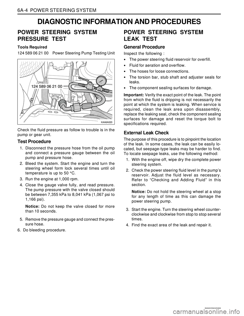
Tools Required
124 589 06 21 00 Power Steering Pump Testing Unit
Check the fluid pressure as follow to trouble is in the
pump or gear unit.
Test Procedure
1. Disconnect the pressure hose from the oil pump
and connect a pressure gauge between the oil
pump and pressure hose.
2. Bleed the system. Start the engine and turn the
steering wheel form lock several times until oil
temperature is up to 50 °C.
3. Run the engine at 1,000 rpm.
4. Close the gauge valve fully, and read pressure.
The pump pressure with the valve closed should
be between 7,355 kPa to 8,041 kPa (1,067 psi to
1,166 psi).
Notice: Do not keep the valve closed for more
than 10 seconds.
5. Remove the pressure gauge and connect the pres-
sure hose.
6. Do bleeding procedure.
POWER STEERING SYSTEM
LEAK TEST
General Procedure
Inspect the following :
The power steering fluid reservoir for overfill.
Fluid for aeration and overflow.
The hoses for loose connections.
The torsion bar, stub shaft and adjuster seals for
leaks.
The component sealing surfaces for damage.
Important: Verify the exact point of the leak. The point
from which the fluid is dripping is not necessarily the
point at which the system is leaking. When service is
required, clean the leak area upon disassembly,
replace the leaking seal, check the component sealing
surfaces for damage and reset the torque bolt to
specifications required.
External Leak Check
The purpose of this procedure is to pinpoint the location
of the leak. In some cases, the leak can be easily lo-
cated, but seepage-type leaks may be harder to find.
To locate seepage leaks, use the following method:
1. With the engine off, wipe dry the complete power
steering system.
2. Check the power steering fluid level in the pump’s
reservoir. Adjust the fluid level as necessary.
Refer to “Checking and Adding Fluid” in this
section.
Notice: Do not hold the steering wheel at a stop
for any length of time as this can damage the
power steering pump.
3. Start the engine. Turn the steering wheel counter-
clockwise and clockwise from stop to stop several
times.
4. Find the exact area of the leak and repair it.
Page 1447 of 2053

POWER STEERING SYSTEM 6A-5
SSANGYONG MY2002
BLEEDING THE POWER
STEERING SYSTEM
1. Disconnect the fuel line. Using a starter motor,
crank the engine and turn the steering wheel from
lock to start 5 or 6 times.
Notice: Do bleeding with engine cranking. If bleed
with idling, there can be a air contact with oil.
2. Connect the fuel feed line and start the engine at
idle speed.
3. Turn the steering wheel from lock to lock until there
is no more air in oil reservoir.
4. Connect the oil level is within specification.
5. By turning the steering wheel left to right, check
the oil level change.
Notice: If oil is not changes more than 5 mm, do
bleeding again. If oil level rises suddenly when
stopped engine, again.
MAINTENANCE
CHECKING AND ADDING FLUID
Notice: When adding fluid or making a complete fluid
change, always use DEXRON. - II power steering fluid.
Failure to use the proper fluid will cause hose and seal
damage and fluid leaks.
1. The power steering fluid level is indicated by marks
on a fluid level indicator on the fluid reservoir cap.
2. If the fluid is warmed up to 66 °C (150 °F), the fluid
level should be between the MAX and MIN marks.
Add fluid as needed.
3. If the fluid is cool, 21 °C (70 °F), the fluid level should
be at the MIN mark. Add fluid as needed.
Page 1448 of 2053

SSANGYONG MY2002
6A-6 POWER STEERING SYSTEM
KAA6A040
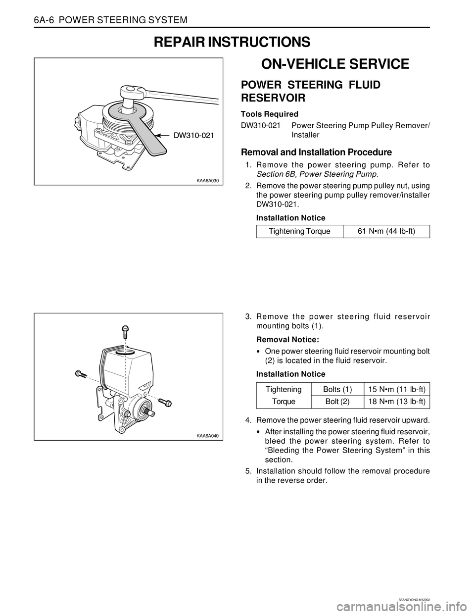
3. Remove the power steering fluid reservoir
mounting bolts (1).
Removal Notice:
One power steering fluid reservoir mounting bolt
(2) is located in the fluid reservoir.
Installation Notice
KAA6A030
ON-VEHICLE SERVICE
POWER STEERING FLUID
RESERVOIR
Tools Required
DW310-021Power Steering Pump Pulley Remover/
Installer
Removal and Installation Procedure
1. Remove the power steering pump. Refer to
Section 6B, Power Steering Pump.
2. Remove the power steering pump pulley nut, using
the power steering pump pulley remover/installer
DW310-021.
Installation Notice
REPAIR INSTRUCTIONS
Tightening Torque 61 Nm (44 lb-ft)
15 Nm (11 lb-ft)
18 Nm (13 lb-ft)
Tightening
TorqueBolts (1)
Bolt (2)
4. Remove the power steering fluid reservoir upward.
After installing the power steering fluid reservoir,
bleed the power steering system. Refer to
“Bleeding the Power Steering System” in this
section.
5. Installation should follow the removal procedure
in the reverse order.
Page 1449 of 2053
POWER STEERING SYSTEM 6A-7
SSANGYONG MY2002
KAA6A050
KAA6A060
4. Disconnect the return line pipe from the power
steering gear outlet.
Installation Notice
KAA6A070
5. Disconnect the pressure line pipe from the power
steering gear inlet.
Installation Notice
POWER STEERING PUMP HOSES
AND PIPES
Removal and Installation Procedure
1. Remove the battery. Refer to Section 1E, Engine
Electrical.
2. Siphon the power steering fluid from the fluid reser-
voir.
3. Disconnect the pressure line pipe from the outlet
connection on the power steering pump and return
hose from the inlet connection on the power
steering fluid reservoir.
Installation Notice
Tightening Torque 44 Nm (33 lb-ft)
Tightening Torque 17 Nm (13 lb-ft)
Tightening Torque 17 Nm (13 lb-ft)