Page 401 of 2053
1D2 -- 6 M161 ENGINE COOLING
D AEW OO M Y_2000
4. After complete draining of the coolant, remove the
hose connector to drain plug and reinstall the drain
plug.
Installation Notice
Tightening Torque
30 NSm (22 lb-ft)
5. Tighten the radiator lower drain cock.
6. Remove the de-- aeration hose clamp in the water
pump and remove the de-- aeration hose.
7. Fill up the coolant through the coolant reservoir
tank.
Notice
DMatchtheanti--freezeandthewaterratioto50:50.
DSupplement the coolant until the coolant overflows to
the deaeration hose.
8. Insert the de--aeration hose and completely tighten
the clamp.
9. Check the coolant level in the coolant reservoir tank.
10. Warm up(until thermostat is opened) the engine and
recheck the coolant level in the reservoir tank and fill
up the coolant if necessary.
Page 410 of 2053
M161 ENGINE COOLING 1D2 -- 15
D AEW OO M Y_2000
REMOVAL AND INSTALLATION OF RADIATOR
Preceding Work: Removal of cooling fan shroud
1 Inlet Hose
2 Hose (to Engine)
3 Hose (to 3-- way Connector)
4 Make-- up Hose (to Coolant Reservoir)
5 3-- way Connector
6 Automatic Transmission Oil Cooling Hose
(A/T Equippend Vehicle)7 Bolt (M6 X 20, 4 pieces)
3--7 NSm (27-- 62 lb-in) .....................
8 Insulator
9 Radiator Bracket
10 Radiator
Page 562 of 2053
OM600 ENGINE MECHANICAL 1B3 -- 13
D AEW OO M Y_2000
Removal & Installation Procedure
1. Disconnect the negative terminal of battery.
2. Remove the hood.
3. Remove the skid plate.
Installation Notice
Tightening Torque28-- 47 N∙m (21-- 35 lb-ft)
4. Remove the radiator drain cock and drain the cool-
ant.
Notice
Open the coolant reservoir tank cap.
5. Remove the drain plug (1) and seal (2) from the cyl-
inder block and drain the coolant completely.
6. After draining, replace the seal and reinstall the
drain plug.
Installation Notice
Tightening Torque30 N∙m (22 lb-ft)
7. Disconnect the lower coolant hose from the radiator.
Page 739 of 2053
1D3 -- 4 OM600 ENGINE COOLING
D AEW OO M Y_2000
COOLING SYSTEM LEAKAGE TEST
Tools Required
124589152100Tester
Test
1. Loosen the pressure cap by 1 notch and remove the
cap after.
Notice
Do not remove radiator cap when coolant is above
90°C.
2. Add the coolant to the arrow mark of coolant reser-
voir.
3. Connect the special tool to the injector of reservoir
and apply 1.4bar pressure.
Tester 124 589 15 21 00
4. If the pressure on the tester drops, check the hose,
pipe and leakage and, replace or retighten.
Page 740 of 2053
OM600 ENGINE COOLING 1D3 -- 5
D AEW OO M Y_2000
MAINTENANCE AND REPAIR
ON -- VEHICLE SERVICE
DRAIN AND FILLING OF COOLANT
Preceding Work : Removal of skid plate
Drain / Filling
1. Loosen the pressure cap of reservoir by 1 notch and
remove pressure and then loosen the cap.
Notice
Do not remove radiator cap when coolant is above
90°C.
2. Open the drain plug and drain the coolant.
Notice
Collect the coolant by using the proper bottle.
3. Remove the drain plug(1) and seal(2) of cylinder
block and drain the coolant.
4. Replace the seal to new one and tighten the drain
plug.
Installation Notice
Tightening Torque30 N∙m (22 lb-ft)
5. Tighten the drain plug of the lower radiator.
6. Fill the coolant through coolant reservoir -- tank.
Notice
DA proportion of 50% by volume of water / anticor-
rosion must be ensured.
7. After engine is running at idle speed, check the level
of coolant. If necessary, add enough specified cool-
ant.
Page 1472 of 2053

SSANGYONG MY2002
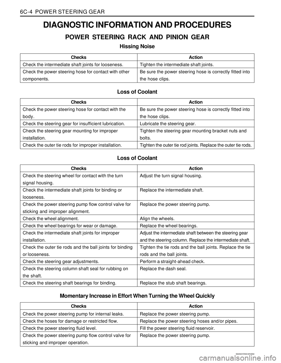
6C-4 POWER STEERING GEAR
DIAGNOSTIC INFORMATION AND PROCEDURES
POWER STEERING RACK AND PINION GEAR
Hissing Noise
Check the intermediate shaft joints for looseness.
Check the power steering hose for contact with other
components.ChecksActionTighten the intermediate shaft joints.
Be sure the power steering hose is correctly fitted into
the hose clips.
Loss of Coolant
Check the power steering hose for contact with the
body.
Check the steering gear for insufficient lubrication.
Check the steering gear mounting for improper
installation.
Check the outer tie rods for improper installation.ChecksActionBe sure the power steering hose is correctly fitted into
the hose clips.
Lubricate the steering gear.
Tighten the steering gear mounting bracket nuts and
bolts.
Tighten the outer tie rod joints. Replace the outer tie rods.
Loss of Coolant
Check the steering wheel for contact with the turn
signal housing.
Check the intermediate shaft joints for binding or
looseness.
Check the power steering pump flow control valve for
sticking and improper alignment.
Check the wheel alignment.
Check the wheel bearings for wear or damage.
Check the intermediate shaft joints for improper
installation.
Check the outer tie rods and the ball joints for binding
or looseness.
Check the steering gear adjustments.
Check the steering column shaft seal for rubbing on
the shaft.
Check the steering shaft bearings for binding.ChecksActionAdjust the turn signal housing.
Replace the intermediate shaft.
Replace the power steering pump.
Align the wheels.
Replace the wheel bearings.
Adjust the intermediate shaft between the steering gear
and the steering column. Replace the intermediate shaft.
Tighten the tie rods and the ball joints. Replace the tie
rods and the ball joints.
Perform a straight-ahead check.
Replace the dash seal.
Replace the stub shaft bearings.
Check the power steering pump for internal leaks.
Check the hoses for damage or restricted flow.
Check the power steering fluid level.
Check the power steering pump flow control valve for
sticking and improper operation.ChecksActionReplace the power steering pump.
Replace the power steering hoses and/or pipes.
Fill the power steering fluid reservoir.
Replace the power steering pump.
Momentary Increase in Effort When Turning the Wheel Quickly
Page 1502 of 2053

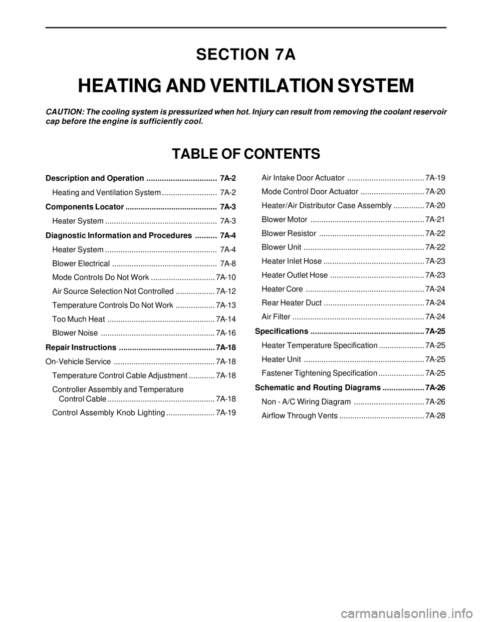
SECTION 7A
HEATING AND VENTILATION SYSTEM
CAUTION: The cooling system is pressurized when hot. Injury can result from removing the coolant reservoir
cap before the engine is sufficiently cool.
TABLE OF CONTENTS
Description and Operation ................................7A-2
Heating and Ventilation System .........................7A-2
Components Locator ..........................................7A-3
Heater System ...................................................7A-3
Diagnostic Information and Procedures ..........7A-4
Heater System ...................................................7A-4
Blower Electrical ................................................7A-8
Mode Controls Do Not Work .............................7A-10
Air Source Selection Not Controlled ..................7A-12
Temperature Controls Do Not Work ..................7A-13
Too Much Heat .................................................7A-14
Blower Noise ....................................................7A-16
Repair Instructions ............................................7A-18
On-Vehicle Service..............................................7A-18
Temperature Control Cable Adjustment ............7A-18
Controller Assembly and Temperature
Control Cable .................................................7A-18
Control Assembly Knob Lighting ......................7A-19Air Intake Door Actuator ...................................7A-19
Mode Control Door Actuator .............................7A-20
Heater/Air Distributor Case Assembly ..............7A-20
Blower Motor ....................................................7A-21
Blower Resistor ................................................7A-22
Blower Unit .......................................................7A-22
Heater Inlet Hose ..............................................7A-23
Heater Outlet Hose ...........................................7A-23
Heater Core......................................................7A-24
Rear Heater Duct ..............................................7A-24
Air Filter ............................................................7A-24
Specifications .................................................... 7A-25
Heater Temperature Specification .....................7A-25
Heater Unit .......................................................7A-25
Fastener Tightening Specification .....................7A-25
Schematic and Routing Diagrams ................... 7A-26
Non - A/C Wiring Diagram ................................7A-26
Airflow Through Vents .......................................7A-28
Page 1505 of 2053

SSANGYONG MY2002
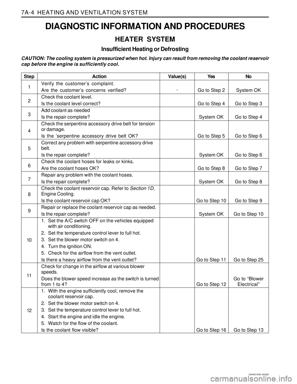
7A-4 HEATING AND VENTILATION SYSTEM
DIAGNOSTIC INFORMATION AND PROCEDURES
HEATER SYSTEM
Insufficient Heating or Defrosting
CAUTION: The cooling system is pressurized when hot. Injury can result from removing the coolant reservoir
cap before the engine is sufficiently cool.
Step
1
2
3
4
5
6
7
8
9
10
11
12
Action
Verify the customer’s complaint.
Are the customer’s concerns verified?
Check the coolant level.
Is the coolant level correct?
Add coolant as needed
Is the repair complete?
Check the serpentine accessory drive belt for tension
or damage.
Is the ’serpentine accessory drive belt OK?
Correct any problem with serpentine accessory drive
belt.
Is the repair complete?
Check the coolant hoses for leaks or kinks.
Are the coolant hoses OK?
Repair any problem with the coolant hoses.
Is the repair complete?
Check the coolant reservoir cap. Refer to Section 1D,
Engine Cooling.
Is the coolant reservoir cap OK?
Repair or replace the coolant reservoir cap as needed.
Is the repair complete?
1. Set the A/C switch OFF on the vehicles equipped
with air conditioning.
2. Set the temperature control lever to full hot.
3. Set the blower motor switch on 4.
4. Turn the ignition ON.
5. Check for the airflow from the vent outlet.
Is there a heavy airflow from the vent outlet?
Check for change in the airflow at various blower
speeds.
Does the blower speed increase as the switch is turned
from 1 to 4?
1. With the engine sufficiently cool, remove the
coolant reservoir cap.
2. Set the blower motor switch on 4.
3. Set the temperature control lever to full hot.
4. Start the engine and idle the engine.
5. Watch for the flow of the coolant.
Is the coolant flow visible?Yes
Go to Step 2
Go to Step 4
System OK
Go to Step 5
System OK
Go to Step 8
System OK
Go to Step 10
System OK
Go to Step 11
Go to Step 12
Go to Step 16No
System OK
Go to Step 3
Go to Step 4
Go to Step 6
Go to Step 6
Go to Step 7
Go to Step 8
Go to Step 9
Go to Step 10
Go to Step 25
Go to “Blower
Electrical”
Go to Step 13 Value(s)
-