1997 SSANGYONG KORANDO charging
[x] Cancel search: chargingPage 468 of 2053

1F2 -- 50 M161 ENGINE CONTROLS
D AEW OO M Y_2000
PURGE CONTROL VALVE
YAA1F440
The fuel vaporization control system is installed to inhibit the fuel vaporized gas from discharging into the atmosphere.
The fuel vaporized gas that is accumulated in the canister abstracts through the purge control valve purification during
the engine combustion (except the decreasing mode) and coolant temperature of over 80°C. For this reason, the En-
gine Control Module (ECM) transacts the engine speed, air inflow quantity, coolant temperature, and intake tempera-
ture.
The purge control valve is activated by the ECM frequency according with the engine rotating speed to adjust the
purification rate. The purification rate is determined by the continuous valve opening interval.
The purge control valve is activated by the ECM for the following conditions:
DCoolant temperature of over 80°C
DEngine speed of over 1,000 rpm
D2 minutes after starting
DWhen the fuel cut -- off mode is not activated
Page 513 of 2053

M161 ENGINE CONTROLS 1F2 -- 95
D AEW OO M Y_2000
MAINTENANCE AND REPAIR
YAA1F700
ON VEHICLE SERVICE
DISCHARGING THE PRESSURE IN
FUEL SYSTEM
Removal and Installation Procedure
1. Remove the fuel pressure test connector.
Installation Notice
Tightening Torque
25 NSm (18 lb-ft)
YAA1F710
2. Remove the fuel pressure in fuel system by pressing
the service valve with a clean, pointy tool.
Notice:Place a cloth so that the fuel doesn’t stain
around.
3. Installation should follow the removal procedure in
the reverse order.
YAA1F170
FUEL PUMP
Tools Required
661 589 00 46 00 Fuel Tank Cap Wrench
Removal and Installation Procedure
Caution: The fuel system is under pressure. To
avoid fuel spillage and the risk of personal injury or
fire, it is necessary to relieve the fuel system pres -
sure before disconnecting the fuel lines.
1. Relieve the fuel system pressure. Refer to “Discharg-
ing the Pressure in Fuel System” in this section.
2. Disconnect the negative battery cable.
3. Put aside the floor carpet to remove the fuel pump ac-
cess cover.
4. Remove the fuel pump access cover.
5. Remove the fuel pump wiring connectors.
6. Disconnect the fuel supply and return pipes.
7. Remove the fuel pump locking cap band.
Page 514 of 2053

1F2 -- 96 M161 ENGINE CONTROLS
D AEW OO M Y_2000
YAA1F550
8. Using the fuel tank cap wrench 661 589 00 46 00,
remove the locking cap.
9. Remove the pump from the fuel tank.
Notice:Check the condition of the seal and replace if
necessary. Drain the fuel before removing the pump.
10. Perform an operational check of the fuel pump.
11. Installation should follow the removal procedure in
the reverse order.
YAA1F190
FUEL FILTER
Removal and Installation Procedure
1. Disconnect the negative battery cable.
Caution: The fuel system is under pressure. To
avoid fuel spillage and the risk of personal injury or
fire, it is necessary to relieve the fuel system pres -
sure before disconnecting the fuel lines.
2. Relieve the fuel system pressure. Refer to “Dis-
charging the Pressure in Fuel System” in this sec-
tion.
3. Disconnect the fuel lines from the fuel filter.
Installation Notice
Tightening Torque
28 NSm (21 lb-ft)
4. Remove the fuel filter mounting bracket bolt .
Installation Notice
Tightening Torque
6NSm (53 lb-in)
Notice:Place the fuel pump pad. There may be a corro-
sion due to the contact between the fuel filter and the
bracket.
5. Remove the fuel filter.
6. Install the fuel filter.
7. Perform a leak test of the fuel filter.
8. Installation should follow the removal procedure in
the reverse order.
Page 515 of 2053

M161 ENGINE CONTROLS 1F2 -- 97
D AEW OO M Y_2000
KAA1F370
FUEL TANK
Removal and Installation Procedure
Caution: The fuel system is under pressure. To
avoid fuel spillage and the risk of personal injury or
fire, it is necessary to relieve the fuel system pres -
sure before disconnecting the fuel lines.
1. Relieve the fuel pressure. Refer to “Discharging the
Pressure in Fuel System” in this section.
2. Disconnect the negative battery cable.
3. Drain the fuel tank.
4. Put aside the floor carpet to remove the fuel pump
access cover.
5. Remove the fuel pump access cover.
YAA1F170
6. Disconnect the return line.
7. Disconnect the supply line.
8. Disconnect the fuel tank-to-canister hose from the
fuel tank.
9. Disconnect the fuel pump wiring connector.
KAB1F370
10. Disconnect the fuel filler hose and air vent hose from
the fuel tank.
11. Support the fuel tank.
12. Remove the fuel tank retaining nuts.
Installation Notice
Tightening Torque
38 NSm (28 lb-ft)
13. Carefully lower the fuel tank.
Page 1530 of 2053

SECTION 7C
MANUAL CONTROL / SEMIAUTO
TEMPERATURE CONTROL HEATING,
VENTILATION AND AIR CONDITIONING
SYSTEM
CAUTION: Disconnect the negative battery cable before removing or installing any electrical unit or when
a tool or equipment could easily come in contact with exposed electrical terminals. Disconnecting this
cable will help prevent personal injury and damage to the vehicle. The ignition must also be in LOCK
unless other-wise noted.
TABLE OF CONTENTS
Specifications.......................................................7C-2
Refrigerant..........................................................7C-2
Evaporator Unit....................................................7C-2
Blower Unit..........................................................7C-2
Compressor.........................................................7C-2
Condenser...........................................................7C-2
Receiver Drier......................................................7C-2
Pressure Switch...................................................7C-3
Air Filter...............................................................7C-3
Heater Unit..........................................................7C-3
Fastener Tightening Specifications.......................7C-3
Diagnosis..............................................................7C-4
Defectives in Fan Motor Circuit.............................7C-5
Defectives in Compressor Circuit.........................7C-6
Diagnosis Using the Manifold Gauge...................7C-7Component Locator.............................................7C-9
Ventilation............................................................7C-9
Heater System ................................................... 7C-11
Air Conditioner System...................................... 7C-12
Diesel Engine .................................................... 7C-12
Gasoline Engine................................................ 7C-13
Maintenance and Repair................................... 7C-14
Refrigerant Charging .......................................... 7C-14
Compressor Oil Replacement............................ 7C-18
Repair Instructions.............................................. 7C-19
On-Vehicle Service............................................... 7C-19
Condener.......................................................... 7C-19
Receiver Drier.................................................... 7C-21
Air - Conditioner Compressor............................. 7C-23
Heater and Air Conditioner Control Box.............. 7C-24
Air Filter............................................................. 7C-25
Page 1543 of 2053

SSANGYONG MY2002
7C-14 MANUAL & SEMIAUTO-HVAC
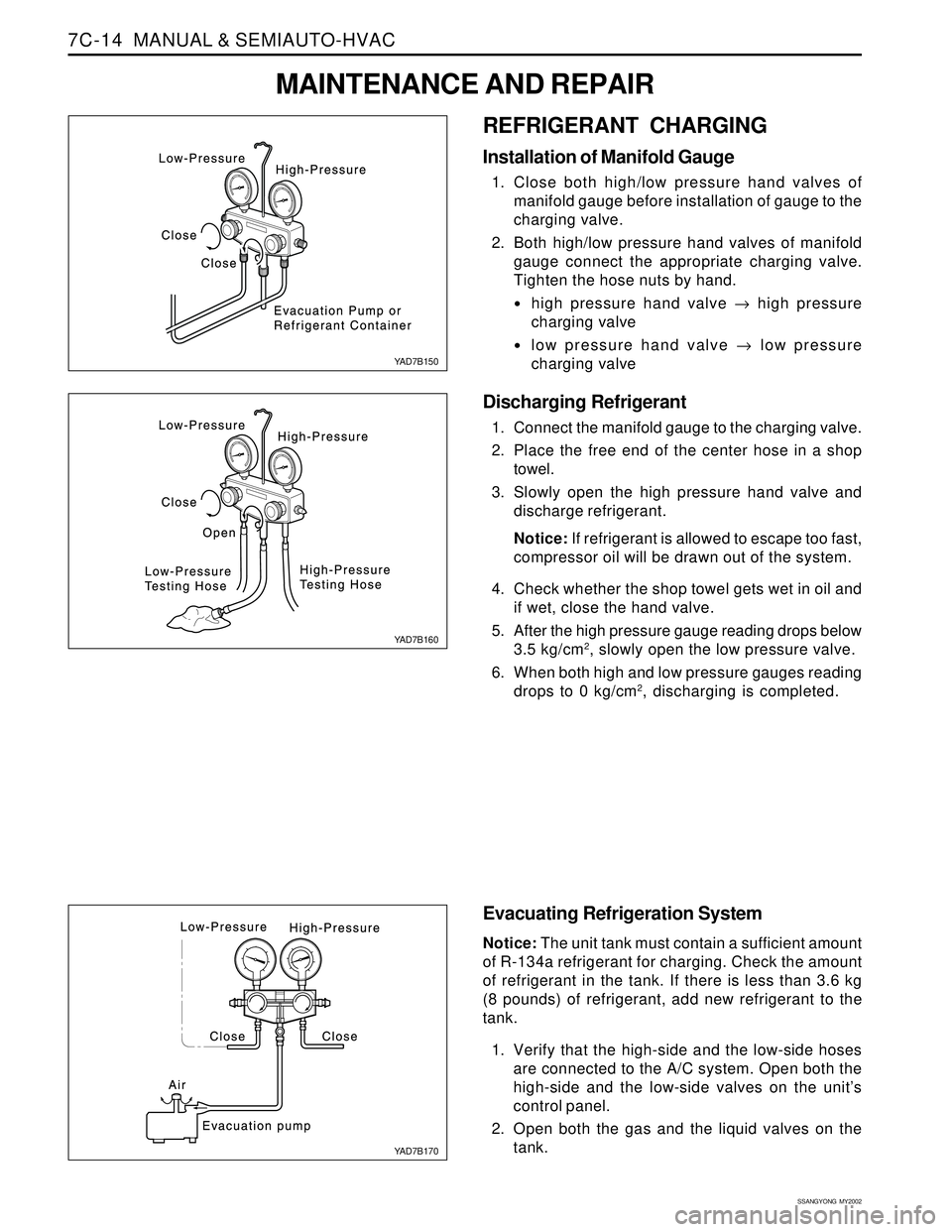
REFRIGERANT CHARGING
Installation of Manifold Gauge
1. Close both high/low pressure hand valves of
manifold gauge before installation of gauge to the
charging valve.
2. Both high/low pressure hand valves of manifold
gauge connect the appropriate charging valve.
Tighten the hose nuts by hand.
high pressure hand valve → high pressure
charging valve
low pressure hand valve → low pressure
charging valve
Discharging Refrigerant
1. Connect the manifold gauge to the charging valve.
2. Place the free end of the center hose in a shop
towel.
3. Slowly open the high pressure hand valve and
discharge refrigerant.
Notice: If refrigerant is allowed to escape too fast,
compressor oil will be drawn out of the system.
4. Check whether the shop towel gets wet in oil and
if wet, close the hand valve.
5. After the high pressure gauge reading drops below
3.5 kg/cm
2, slowly open the low pressure valve.
6. When both high and low pressure gauges reading
drops to 0 kg/cm
2, discharging is completed.
Evacuating Refrigeration System
Notice: The unit tank must contain a sufficient amount
of R-134a refrigerant for charging. Check the amount
of refrigerant in the tank. If there is less than 3.6 kg
(8 pounds) of refrigerant, add new refrigerant to the
tank.
1. Verify that the high-side and the low-side hoses
are connected to the A/C system. Open both the
high-side and the low-side valves on the unit’s
control panel.
2. Open both the gas and the liquid valves on the
tank.
YAD7B150
YAD7B160
YAD7B170
MAINTENANCE AND REPAIR
Page 1544 of 2053

MANUAL & SEMIAUTO-HVAC 7C-15
SSANGYONG MY2002
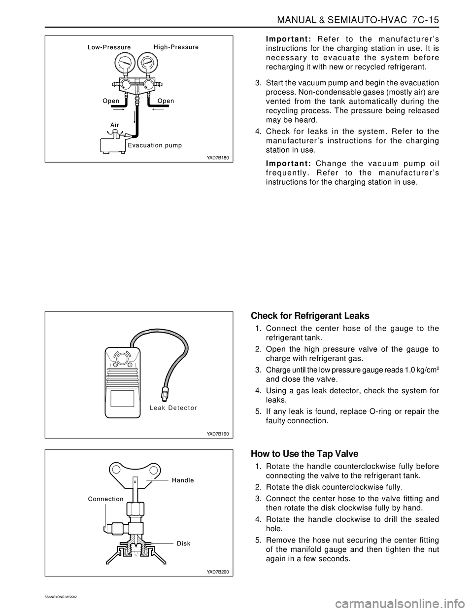
Important: Refer to the manufacturer’s
instructions for the charging station in use. It is
necessary to evacuate the system before
recharging it with new or recycled refrigerant.
3. Start the vacuum pump and begin the evacuation
process. Non-condensable gases (mostly air) are
vented from the tank automatically during the
recycling process. The pressure being released
may be heard.
4. Check for leaks in the system. Refer to the
manufacturer’s instructions for the charging
station in use.
Important: Change the vacuum pump oil
frequently. Refer to the manufacturer’s
instructions for the charging station in use.
Check for Refrigerant Leaks
1. Connect the center hose of the gauge to the
refrigerant tank.
2. Open the high pressure valve of the gauge to
charge with refrigerant gas.
3. Charge until the low pressure gauge reads 1.0 kg/cm
2
and close the valve.
4. Using a gas leak detector, check the system for
leaks.
5. If any leak is found, replace O-ring or repair the
faulty connection.
How to Use the Tap Valve
1. Rotate the handle counterclockwise fully before
connecting the valve to the refrigerant tank.
2. Rotate the disk counterclockwise fully.
3. Connect the center hose to the valve fitting and
then rotate the disk clockwise fully by hand.
4. Rotate the handle clockwise to drill the sealed
hole.
5. Remove the hose nut securing the center fitting
of the manifold gauge and then tighten the nut
again in a few seconds.
YAD7B180
YAD7B190
YAD7B200
Page 1545 of 2053

SSANGYONG MY2002
7C-16 MANUAL & SEMIAUTO-HVAC
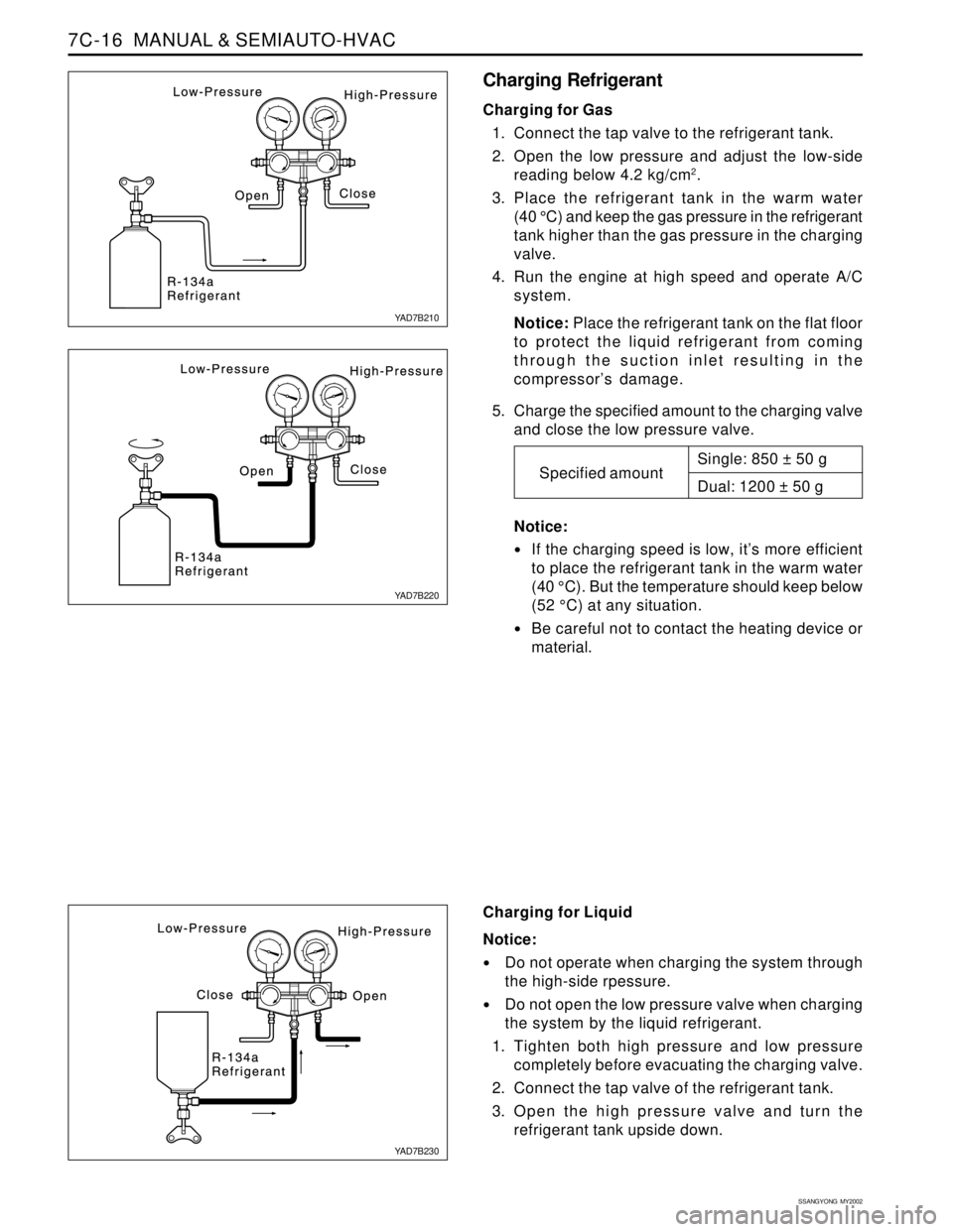
Charging Refrigerant
Charging for Gas
1. Connect the tap valve to the refrigerant tank.
2. Open the low pressure and adjust the low-side
reading below 4.2 kg/cm
2.
3. Place the refrigerant tank in the warm water
(40 °C) and keep the gas pressure in the refrigerant
tank higher than the gas pressure in the charging
valve.
4. Run the engine at high speed and operate A/C
system.
Notice: Place the refrigerant tank on the flat floor
to protect the liquid refrigerant from coming
through the suction inlet resulting in the
compressor’s damage.
5. Charge the specified amount to the charging valve
and close the low pressure valve.
Notice:
If the charging speed is low, it’s more efficient
to place the refrigerant tank in the warm water
(40 °C). But the temperature should keep below
(52 °C) at any situation.
Be careful not to contact the heating device or
material.
Charging for Liquid
Notice:
Do not operate when charging the system through
the high-side rpessure.
Do not open the low pressure valve when charging
the system by the liquid refrigerant.
1. Tighten both high pressure and low pressure
completely before evacuating the charging valve.
2. Connect the tap valve of the refrigerant tank.
3. Open the high pressure valve and turn the
refrigerant tank upside down.Single: 850 ± 50 g
Dual: 1200 ± 50 g
Specified amount
YAD7B210
YAD7B220
YAD7B230