1997 SSANGYONG KORANDO wheel
[x] Cancel search: wheelPage 1084 of 2053
ABS AND TCS 4F-101
SSANGYONG MY2002
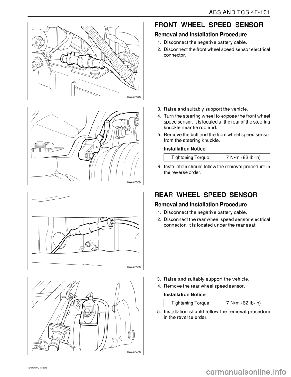
FRONT WHEEL SPEED SENSOR
Removal and Installation Procedure
1. Disconnect the negative battery cable.
2. Disconnect the front wheel speed sensor electrical
connector.
3. Raise and suitably support the vehicle.
4. Turn the steering wheel to expose the front wheel
speed sensor. It is located at the rear of the steering
knuckle near tie rod end.
5. Remove the bolt and the front wheel speed sensor
from the steering knuckle.
Installation Notice
KAA4F370
KAA4F380
Tightening Torque 7 Nm (62 lb-in)
6. Installation should follow the removal procedure in
the reverse order.
REAR WHEEL SPEED SENSOR
Removal and Installation Procedure
1. Disconnect the negative battery cable.
2. Disconnect the rear wheel speed sensor electrical
connector. It is located under the rear seat.
3. Raise and suitably support the vehicle.
4. Remove the rear wheel speed sensor.
Installation Notice
KAA4F390
KAA4F400
Tightening Torque 7 Nm (62 lb-in)
5. Installation should follow the removal procedure
in the reverse order.
Page 1086 of 2053
ABS AND TCS 4F-103
SSANGYONG MY2002
UNIT REPAIR
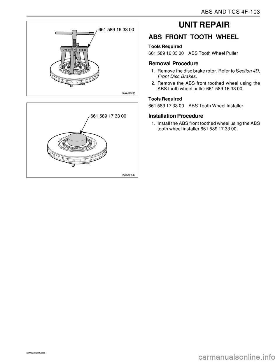
ABS FRONT TOOTH WHEEL
Tools Required
661 589 16 33 00 ABS Tooth Wheel Puller
Removal Procedure
1. Remove the disc brake rotor. Refer to Section 4D,
Front Disc Brakes.
2. Remove the ABS front toothed wheel using the
ABS tooth wheel puller 661 589 16 33 00.
Tools Required
661 589 17 33 00 ABS Tooth Wheel Installer
Installation Procedure
1. Install the ABS front toothed wheel using the ABS
tooth wheel installer 661 589 17 33 00.
KAA4F430
KAA4F440
Page 1087 of 2053
SSANGYONG MY2002
4F-104 ABS AND TCS
SPECIAL TOOLS AND EQUIPMENT
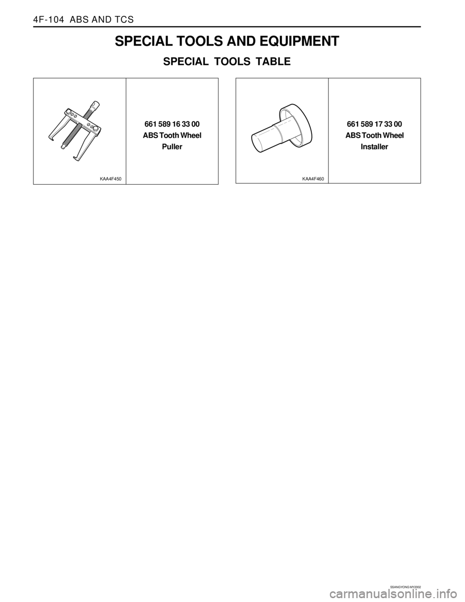
SPECIAL TOOLS TABLE
661 589 16 33 00
ABS Tooth Wheel
Puller661 589 17 33 00
ABS Tooth Wheel
Installer
KAA4F450KAA4F460
Page 1091 of 2053
SSANGYONG MY2002
4G-4 PARKING BRAKE
KAA4G020
KAA4G030
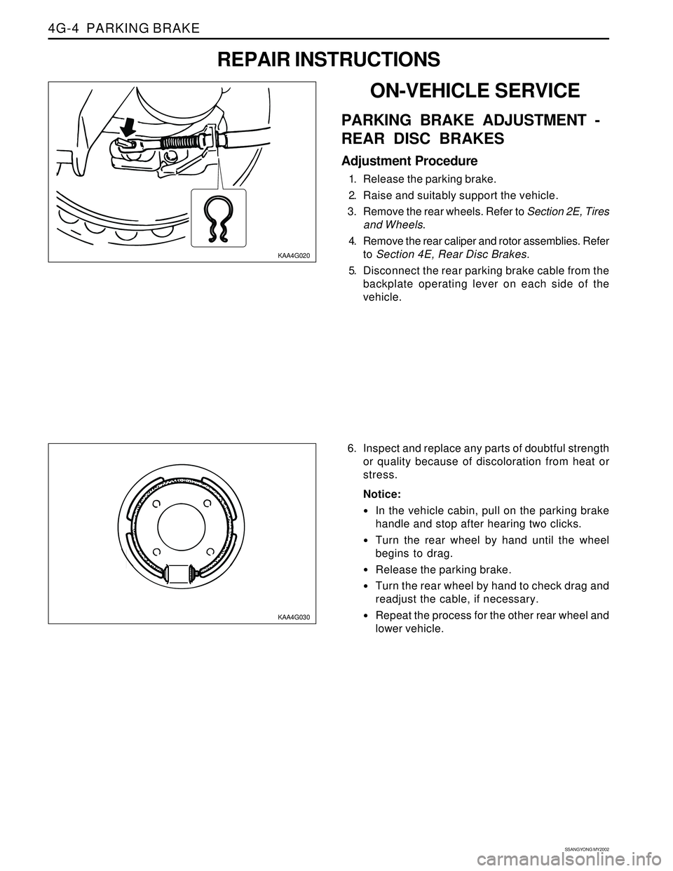
6. Inspect and replace any parts of doubtful strength
or quality because of discoloration from heat or
stress.
Notice:
In the vehicle cabin, pull on the parking brake
handle and stop after hearing two clicks.
Turn the rear wheel by hand until the wheel
begins to drag.
Release the parking brake.
Turn the rear wheel by hand to check drag and
readjust the cable, if necessary.
Repeat the process for the other rear wheel and
lower vehicle.
ON-VEHICLE SERVICE
PARKING BRAKE ADJUSTMENT -
REAR DISC BRAKES
Adjustment Procedure
1. Release the parking brake.
2. Raise and suitably support the vehicle.
3. Remove the rear wheels. Refer to Section 2E, Tires
and Wheels.
4. Remove the rear caliper and rotor assemblies. Refer
to Section 4E, Rear Disc Brakes.
5. Disconnect the rear parking brake cable from the
backplate operating lever on each side of the
vehicle.
REPAIR INSTRUCTIONS
Page 1097 of 2053
AUTOMATIC TRANSMISSION 5A-3
SSANGYONG MY2002
N - Neutral allows the engine to be started and oper-
ated while driving the vehicle. The inhibitor switch
allows the engine to be started. There is no power
transferred through the transmission in Neutral. But
the final drive is not locked by the parking pawl, so
thewheels are free to rotate.
D - Overdrive range is used for all normal driving
conditions. 4th gear (overdrive gear) reduces the
fuel consumption and the engine noise. Engine
braking is applied with reduced throttle.
First to second (1 → 2), first to third (1 → 3), second
to third (2 → 3), second to fourth (2 → 4), third to
fourth (3 → 4), fourth to third (4 → 3), fourth to
second (4 → 2), third to second (3 → 2), third to
first (3 → 1) and second to first (2 → 1) shifts are
all available as a function of vehicle speed, throttle
position and the time change rate of the throttle
position.
Downshifts are available for safe passing by
depress-ing the accelerator. Lockup clutch may be
enabled in 3rd and 4th gears depending on vehicle
type.
3 - Manual 3 provides three gear ratios (first through
third) and prevents the transmission from operating
in 4th gear. 3rd gear is used when driving on long
hill roads or in heavy city traffic. Downshifts are
available by depressing the accelerator.
2 - Manual 2 provides two gear ratios (first and
second). It is used to provide more power when
climbing hills or engine braking when driving down
a steep hill or starting off on slippery roads.
1 - Manual 1 is used to provide the maximum engine
braking when driving down the severe gradients.When NORMAL mode is selected upshifts will occur
to maximize fuel economy. When POWER mode is se-
lected, upshifts will occur to give maximum
performance and the POWER mode indicator light is
switched ON.
When WINTER mode is selected, starting in second
gear is facilitated, the WINTER mode indicator light is
switched ON and the POWER mode indicator light is
switched OFF.
Indicator Light
The indicator light is located on the instrument panel.
Auto shift indicator light comes ON when the ignition
switch ON and shows the gear shift control lever
position.
POWER mode indicator light comes ON when the
POWER mode is selected and when the kickdown
switch is depressed.
WINTER mode indicator light comes ON when the
WINTER mode is selected.
CONTROL SYSTEMS
BTRA M74 4WD automatic transmission consists of
two control systems. One is the electronic control
system that monitors vehicle parameters and adjusts
the transmission performance. Another is the hydraulic
control system that implements the commands of the
electronic control system commands.
ELECTRONIC CONTROL SYSTEM
The electronic control system comprises of sensors, a
TCM and seven solenoids. The TCM reads the inputs
and activates the outputs according to values stored
in Read Only Memory (ROM).
The TCM controls the hydraulic control system. This
control is via the hydraulic valve body, which contains
seven electromagnetic solenoids. Six of the seven
solenoids are used to control the line pressure, operate
the shift valves and the torque converter lock-up clutch,
and to turn ON and OFF the two regulator valves that
control the shift feel.
The seventh solenoid is the proportional or Variable
Pressure Solenoid (VPS) which works with the two regu-
lator valves to control shift feel.
Transmission Control Module (TCM)
The TCM is an in-vehicle micro-processor based trans-
mission management system. It is mounted under the
driver’s side front seat in the vehicle cabin.
The TCM contains:
Processing logic circuits which include a central mi-
croprocessor controller and a back-up memory
system.
Input circuits.
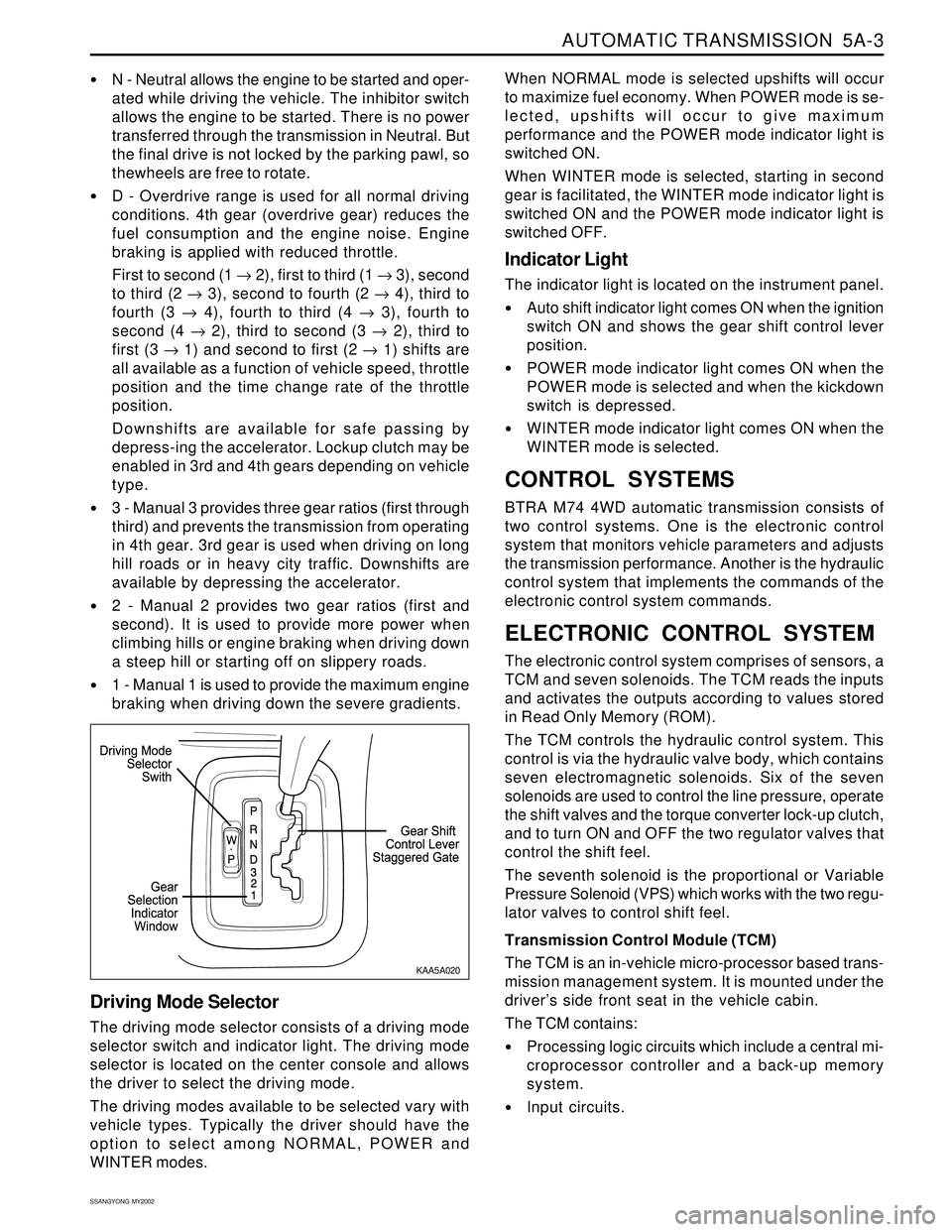
Driving Mode Selector
The driving mode selector consists of a driving mode
selector switch and indicator light. The driving mode
selector is located on the center console and allows
the driver to select the driving mode.
The driving modes available to be selected vary with
vehicle types. Typically the driver should have the
option to select among NORMAL, POWER and
WINTER modes.
KAA5A020
Page 1109 of 2053
AUTOMATIC TRANSMISSION 5A-15
SSANGYONG MY2002
3-4
OWC
X
X
X
X
X 1-2
OWC
X B2
X
X B1
X
X C4
X
X
X
Gear set-sprag-centre support
C1 -C2 -C3 -C4 clutch sub-assembly
Pump assembly
Valve body assembly
One, or a combination of selective washers are used
between the input shaft flange and the number 4
bearing to control the transmission end float. This
arrangement allows for extensive subassembly testing
and simplistic final assembly during production.
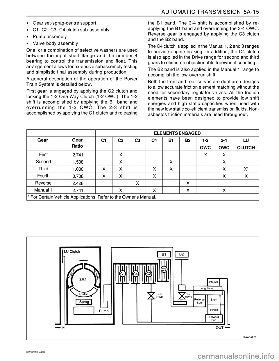
A general description of the operation of the Power
Train System is detailed below.
First gear is engaged by applying the C2 clutch and
locking the 1-2 One Way Clutch (1-2 OWC). The 1-2
shift is accomplished by applying the B1 band and
overrunning the 1-2 OWC. The 2-3 shift is
accomplished by applying the C1 clutch and releasingthe B1 band. The 3-4 shift is accomplished by re-
applying the B1 band and overrunning the 3-4 OWC.
Reverse gear is engaged by applying the C3 clutch
and the B2 band.
The C4 clutch is applied in the Manual 1, 2 and 3 ranges
to provide engine braking. In addition, the C4 clutch
is also applied in the Drive range for second and third
gears to eliminate objectionable freewheel coasting.
The B2 band is also applied in the Manual 1 range to
accomplish the low-overrun shift.
Both the front and rear servos are dual area designs
to allow accurate friction element matching without the
need for secondary regulator valves. All the friction
elements have been designed to provide low shift
energies and high static capacities when used with
the new low static co-efficient transmission fluids. Non-
asbestos friction materials are used throughout.
Gear
First
Second
Third
Fourth
Reverse
Manual 1Gear
Ratio
2.741
1.508
1.000
0.708
2.428
2.741C1
X
XC2
X
X
X
X
XC3
XLU
CLUTCH
X*
X ELEMENTS ENGAGED
* For Certain Vehicle Applications, Refer to the Owner's Manual.
KAA5A250
Page 1110 of 2053
5A-16 AUTOMATIC TRANSMISSION
SSANGYONG MY2002
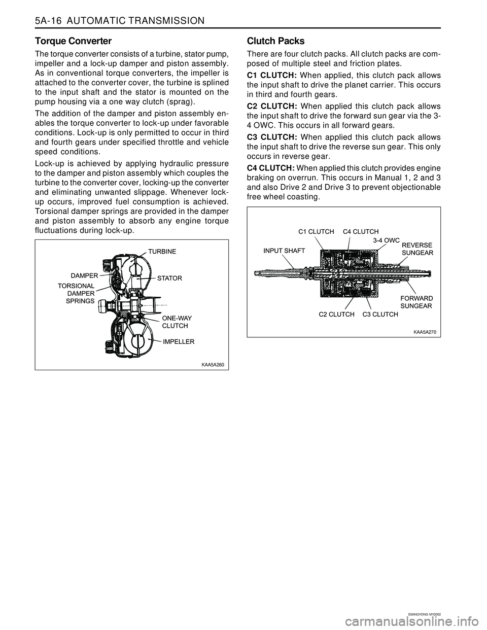
Torque Converter
The torque converter consists of a turbine, stator pump,
impeller and a lock-up damper and piston assembly.
As in conventional torque converters, the impeller is
attached to the converter cover, the turbine is splined
to the input shaft and the stator is mounted on the
pump housing via a one way clutch (sprag).
The addition of the damper and piston assembly en-
ables the torque converter to lock-up under favorable
conditions. Lock-up is only permitted to occur in third
and fourth gears under specified throttle and vehicle
speed conditions.
Lock-up is achieved by applying hydraulic pressure
to the damper and piston assembly which couples the
turbine to the converter cover, locking-up the converter
and eliminating unwanted slippage. Whenever lock-
up occurs, improved fuel consumption is achieved.
Torsional damper springs are provided in the damper
and piston assembly to absorb any engine torque
fluctuations during lock-up.
Clutch Packs
There are four clutch packs. All clutch packs are com-
posed of multiple steel and friction plates.
C1 CLUTCH: When applied, this clutch pack allows
the input shaft to drive the planet carrier. This occurs
in third and fourth gears.
C2 CLUTCH: When applied this clutch pack allows
the input shaft to drive the forward sun gear via the 3-
4 OWC. This occurs in all forward gears.
C3 CLUTCH: When applied this clutch pack allows
the input shaft to drive the reverse sun gear. This only
occurs in reverse gear.
C4 CLUTCH: When applied this clutch provides engine
braking on overrun. This occurs in Manual 1, 2 and 3
and also Drive 2 and Drive 3 to prevent objectionable
free wheel coasting.
KAA5A260
KAA5A270
Page 1170 of 2053
AUTOMATIC TRANSMISSION 5A-75
SSANGYONG MY2002
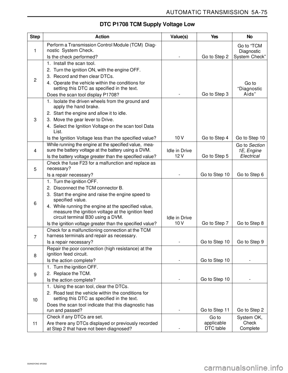
DTC P1708 TCM Supply Voltage Low
1Perform a Transmission Control Module (TCM) Diag-
nostic System Check.
Is the check performed?
1. Install the scan tool.
2. Turn the ignition ON, with the engine OFF.
3. Record and then clear DTCs.
4. Operate the vehicle within the conditions for
setting this DTC as specified in the text.
Does the scan tool display P1708?
1. Isolate the driven wheels from the ground and
apply the hand brake.
2. Start the engine and allow it to idle.
3. Move the gear lever to Drive.
4. Select the Ignition Voltage on the scan tool Data
List.
Is the Ignition Voltage less than the specified value?
While running the engine at the specified value, mea-
sure the battery voltage at the battery using a DVM.
Is the battery voltage greater than the specified value?
Check the fuse F23 for a malfunction and replace as
necessary?
Is a repair necessary?
1. Turn the ignition OFF.
2. Disconnect the TCM connector B.
3. Start the engine and raise the engine speed to
specified value.
4. While running the engine at the specified value,
measure the ignition voltage at the ignition feed
circuit terminal B30 using a DVM.
Is the ignition voltage greater than the specified value?
Check for a malfunctioning connection at the TCM
harness terminals and repair as necessary.
Is a repair necessary?
Repair the poor connection (high resistance) at the
ignition feed circuit.
Is the action complete?
1. Turn the ignition OFF.
2. Replace the TCM.
Is the action complete?
1. Using the scan tool, clear the DTCs.
2. Road test the vehicle within the conditions for
setting this DTC as specified in the text.
Does the scan tool indicate that this diagnostic has
run and passed?
Check if any DTCs are set.
Are there any DTCs displayed or previously recorded
at Step 2 that have not been diagnosed?
StepAction Value(s) Yes No
2
3
5
- Go to Step 10 Go to Step 9 6 4
- Go to Step 10 - 7
- Go to Step 10 - 8
- Go to Step 11 Go to Step 2 9
10
- Go to Step 2Go to “TCM
Diagnostic
System Check”
10 V Go to Step 4 Go to Step 10
- Go to Step 3 Go to
“Diagnostic
Aids”
11
-Go to
applicable
DTC tableSystem OK,
Check
Complete
- Go to Step 10 Go to Step 6
Idle in Drive
10 V Go to Step 7 Go to Step 8
Idle in Drive
12 V Go to Step 5 Go to Section
1E, Engine
Electrical