1997 SSANGYONG KORANDO engine coolant
[x] Cancel search: engine coolantPage 1507 of 2053
SSANGYONG MY2002
7A-6 HEATING AND VENTILATION SYSTEM
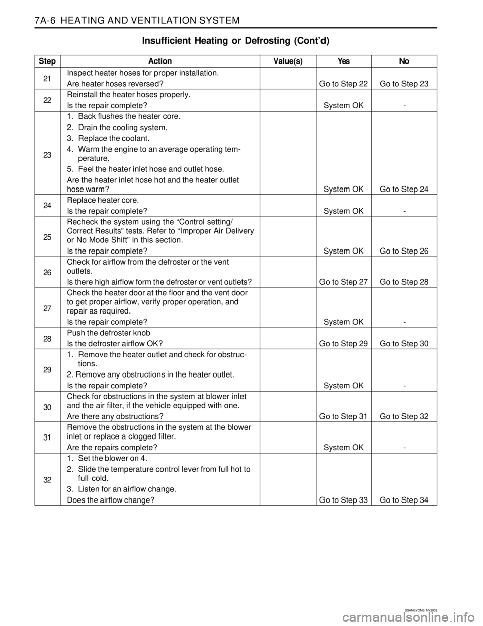
Insufficient Heating or Defrosting (Cont’d)
Step
21
22
23
24
25
26
27
28
29
30
31
32Action
Inspect heater hoses for proper installation.
Are heater hoses reversed?
Reinstall the heater hoses properly.
Is the repair complete?
1. Back flushes the heater core.
2. Drain the cooling system.
3. Replace the coolant.
4. Warm the engine to an average operating tem-
perature.
5. Feel the heater inlet hose and outlet hose.
Are the heater inlet hose hot and the heater outlet
hose warm?
Replace heater core.
Is the repair complete?
Recheck the system using the “Control setting/
Correct Results” tests. Refer to “Improper Air Delivery
or No Mode Shift” in this section.
Is the repair complete?
Check for airflow from the defroster or the vent
outlets.
Is there high airflow form the defroster or vent outlets?
Check the heater door at the floor and the vent door
to get proper airflow, verify proper operation, and
repair as required.
Is the repair complete?
Push the defroster knob
Is the defroster airflow OK?
1. Remove the heater outlet and check for obstruc-
tions.
2. Remove any obstructions in the heater outlet.
Is the repair complete?
Check for obstructions in the system at blower inlet
and the air filter, if the vehicle equipped with one.
Are there any obstructions?
Remove the obstructions in the system at the blower
inlet or replace a clogged filter.
Are the repairs complete?
1. Set the blower on 4.
2. Slide the temperature control lever from full hot to
full cold.
3. Listen for an airflow change.
Does the airflow change?Yes
Go to Step 22
System OK
System OK
System OK
System OK
Go to Step 27
System OK
Go to Step 29
System OK
Go to Step 31
System OK
Go to Step 33No
Go to Step 23
-
Go to Step 24
-
Go to Step 26
Go to Step 28
-
Go to Step 30
-
Go to Step 32
-
Go to Step 34 Value(s)
Page 1573 of 2053
FATC-HAVC 7D-19
SSANGYONG MY2002
KAA7D230
KAA7D240
KAA7D250
KAA7D260
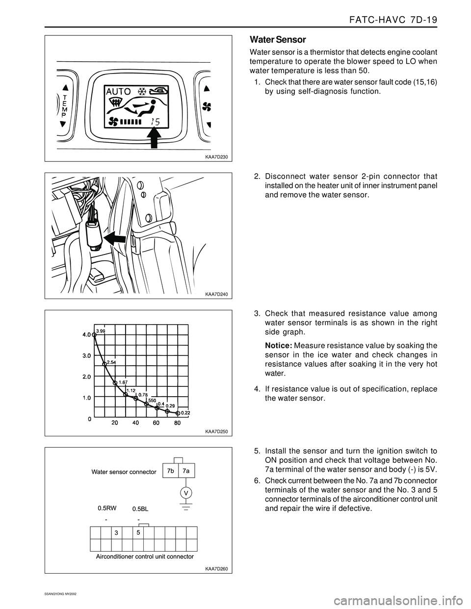
Water Sensor
Water sensor is a thermistor that detects engine coolant
temperature to operate the blower speed to LO when
water temperature is less than 50.
1. Check that there are water sensor fault code (15,16)
by using self-diagnosis function.
2. Disconnect water sensor 2-pin connector that
installed on the heater unit of inner instrument panel
and remove the water sensor.
3. Check that measured resistance value among
water sensor terminals is as shown in the right
side graph.
Notice: Measure resistance value by soaking the
sensor in the ice water and check changes in
resistance values after soaking it in the very hot
water.
4. If resistance value is out of specification, replace
the water sensor.
5. Install the sensor and turn the ignition switch to
ON position and check that voltage between No.
7a terminal of the water sensor and body (-) is 5V.
6. Check current between the No. 7a and 7b connector
terminals of the water sensor and the No. 3 and 5
connector terminals of the airconditioner control unit
and repair the wire if defective.
Page 1671 of 2053
SSANGYONG MY2002
9A-20 BODY WIRING SYSTEM
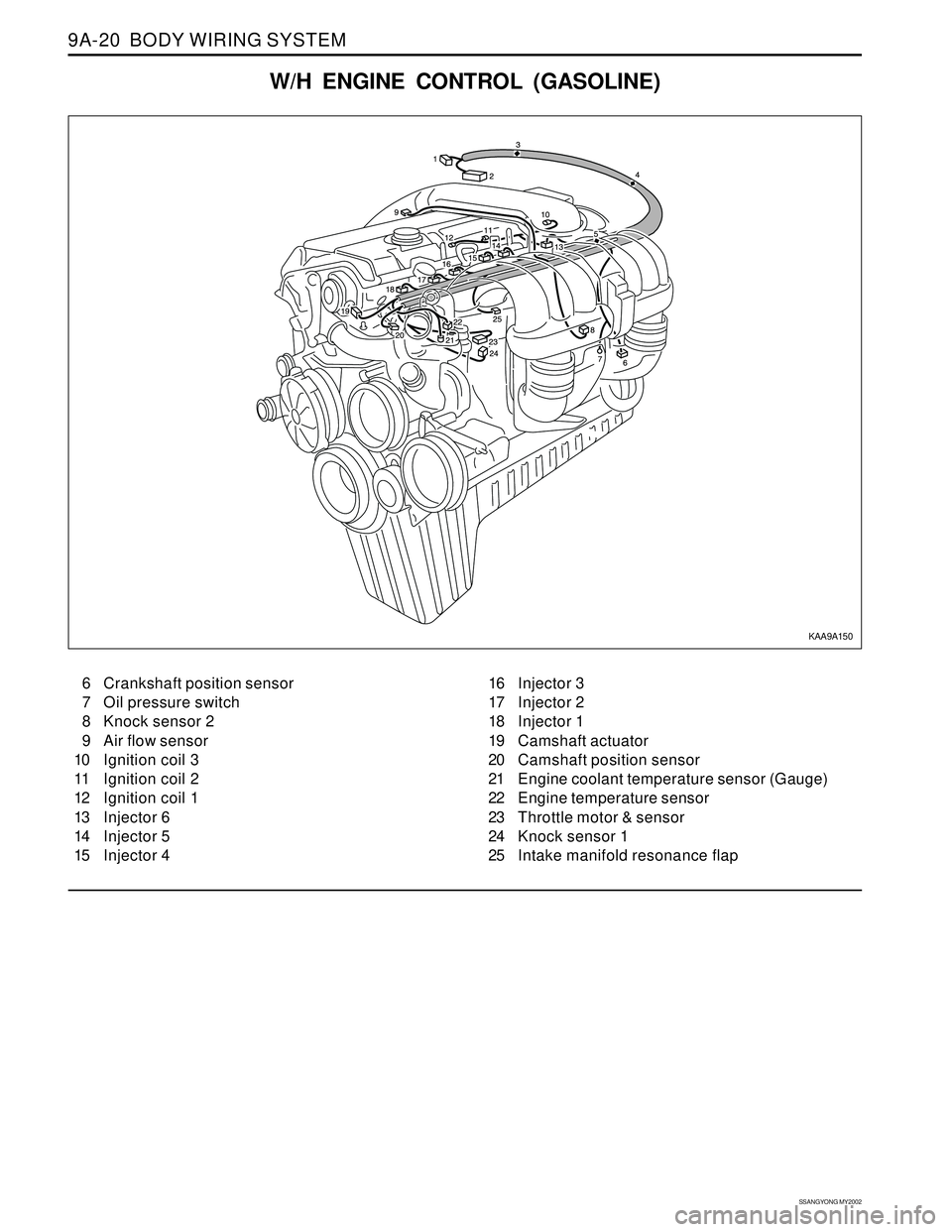
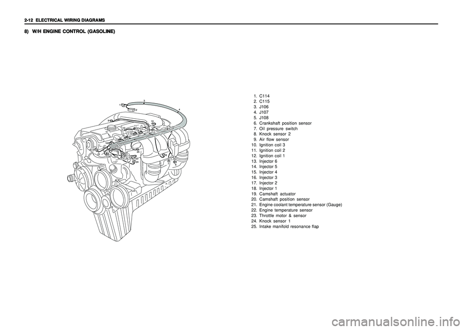
W/H ENGINE CONTROL (GASOLINE)
6 Crankshaft position sensor
7 Oil pressure switch
8 Knock sensor 2
9 Air flow sensor
10 Ignition coil 3
11 Ignition coil 2
12 Ignition coil 1
13 Injector 6
14 Injector 5
15 Injector 416 Injector 3
17 Injector 2
18 Injector 1
19 Camshaft actuator
20 Camshaft position sensor
21 Engine coolant temperature sensor (Gauge)
22 Engine temperature sensor
23 Throttle motor & sensor
24 Knock sensor 1
25 Intake manifold resonance flap
KAA9A150
Page 1672 of 2053
BODY WIRING SYSTEM 9A-21
SSANGYONG MY2002
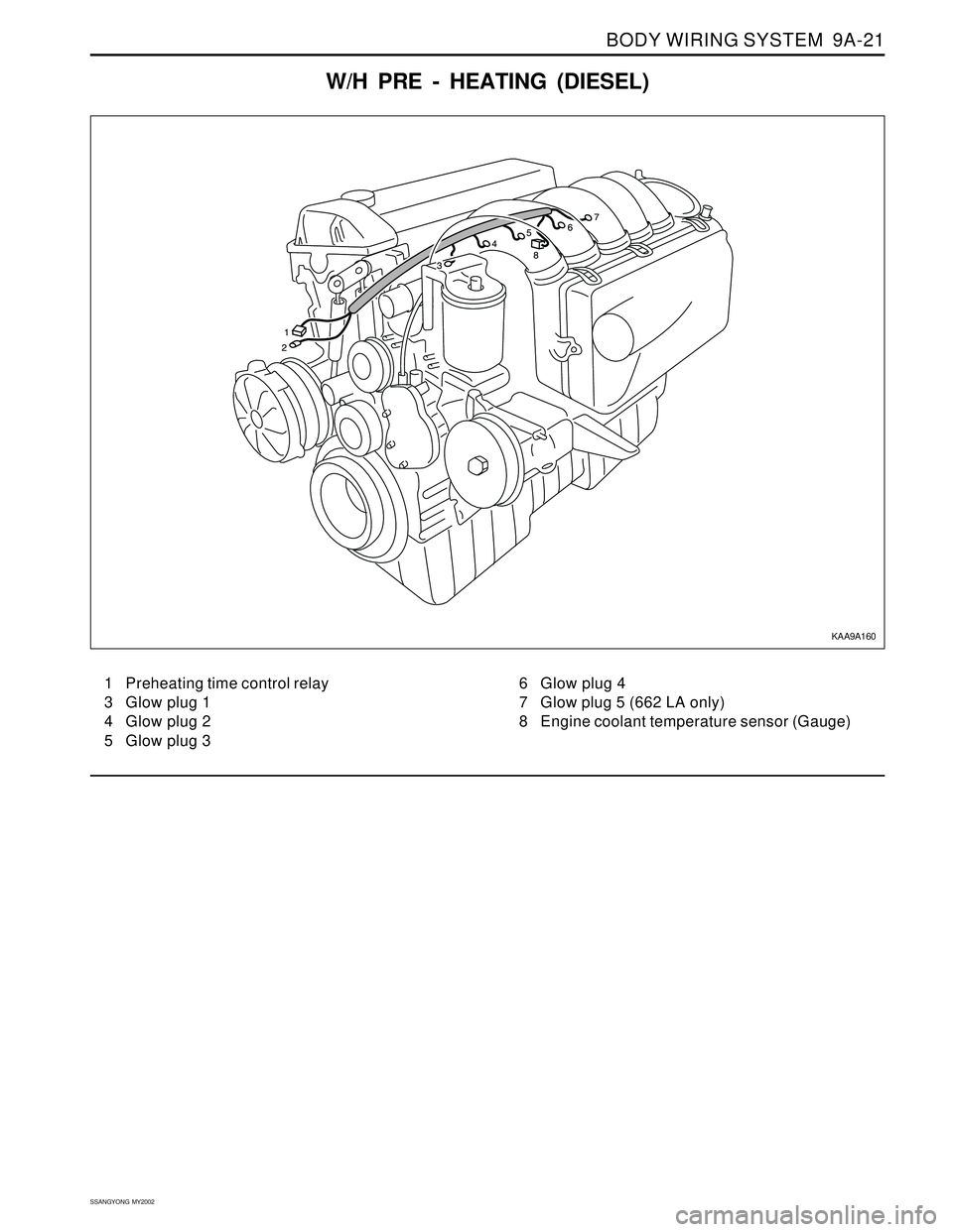
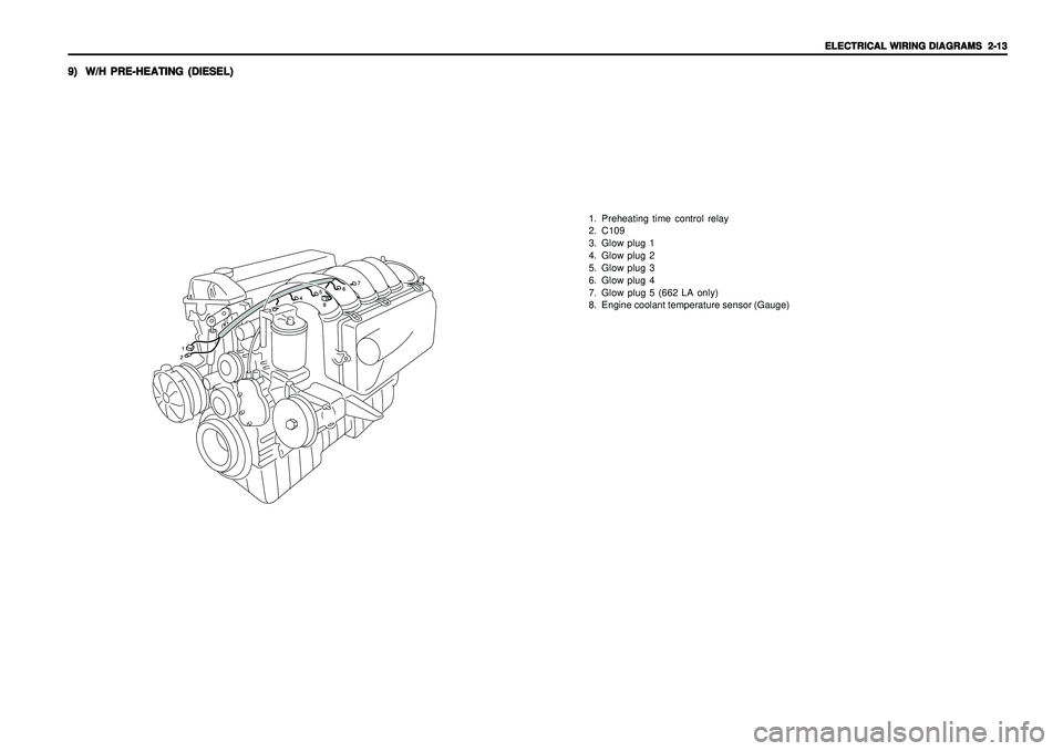
W/H PRE - HEATING (DIESEL)
1 Preheating time control relay
3 Glow plug 1
4 Glow plug 2
5 Glow plug 36 Glow plug 4
7 Glow plug 5 (662 LA only)
8 Engine coolant temperature sensor (Gauge)
KAA9A160
Page 1719 of 2053

SSANGYONG MY2002
9E-2 INSTRUMENTATION, DRIVER INFORMATION
DESCRIPTION AND OPERATION
CIGAR LIGHTER
The cigar lighter is located in the front portion of the
floor console. To use the lighter, push it in completely.
When the lighter is hot, it will release itsef from contact
with the heating element. The lighter and the heating
element can be damaged if the lighter does not fully
release itsef from the heating element.
ASHTRAY
The ashtray is located in the console. To access the
ashtray, pullit out of the ashtray housing. The ashtray
lamp will go on when the parking lamps or headlamps
are turned on.
INSTRUMENT PANEL VENTS
The center and the side vents in the instrument panel
can be adjusted up and down and from side to side.
The side vents can also be aimed toward the side
windows to defog them.
GLOVE BOX
The glove box can be opened by pulling upon the latch
handle.
DIGITAL CLOCK
The digital clock is located in the instrument cluster.
INSTRUMENT CLUSTER
The instrument cluster is located above the steering
column and in the instrument cluster trim panel. The
instrument cluster contains the instruments that
provide the driver with vehicle performance information.
The instrument cluster contains a speedometer, a
tachometer, an odometer, a trip odometer, a
temperature gauge, a fuel gauge, and several indicator
lamps. For replacement of the indicator lamp bulbs
contained in the instrument cluster, refer to “Instrument
Cluster Indicator Lamps Specifications” in the section.
SPEEDOMETER AND
TACHOMETER
The speedometer measures the speed of the vehicle
in km/h (with mph) or mph (with km/h). It consists of
an instrument cluster gauge connected to the vehicle
speed sensor on the transaxle output shaft. The
tachometer measures the engine’s speed in terms of
thousands of revolutions per minute. It consists of an
instrument cluster gauge connected to a sending unit
in the engine con-trol module. Do not operate the
engine in the red zone. Engine damage may occur.
TRIP ODOMETER
The trip odometer measures the distance the vehicle
has traveled since it was last reset. It consists of an
instrument cluster gauge connected to the sending unit
on the tasnsaxle output shaft. The trip oddometer can
be record the distance traveled from any starting point.
FUEL GAUGE
The fuel gauge consists of an instrument cluster gauge
connected to a sending unit in the fuel tank. The fuel
gauge indicates the quantity of fuel in the tank only
when the ignition is turned to ON or ACC. When the
ignition is turned to LOCK or START, the pointer may
come to rest at any position.
TEMPERATURE GAUGE
The temperature gauge consists of an instrument
cluster gauge connected to a temperature sensor that
is in con-tact with the circulating engine coolant. The
temperature gauge indicates the temperature of the
coolant. Prolonged driving or idling in very hot weather
may cause the pointer to move beyond the center of
the gauge. The engine is overheating if the pointer
moves into the red zone at the upper limit of the gauge.
INSTRUMENT CLUSTER
INDICATOR LAMPS
The instrument cluster contains indicator lamps that
indicatethe functioning of certain systems or the
existenceof potential problems with the operation of
the vehicle. The indicator lamps are replaceable. For
replacement of the indicator lamps contained in the
instrument cluster, refer to “instrument cluster indicator
lamps specifications” in this section.
CHIME MODULE
The chime module will sound to bring attention to one
or more of the following conditions:
The lights are on and the ignition not in ACC, ON,
or START.
The ignition key is in the ignition switch when the
driver’s side door is open.
The seat belt is unbuckled when the ignition is in
ACC, ON, or START.
Voltage is supplied at all times through the fuse block
to power the chime module.
Page 1725 of 2053

SSANGYONG MY2002
9E-8 INSTRUMENTATION, DRIVER INFORMATION
TEMPERATURE GAUGE
Temperature Gauge Inoperative, Other Gauges OK
Step
1
2
3
4
5
6
7
8
9Action
Allow the engine to cool to room temperature.
With the ignition ON, does the temperature gauge
always read at the high end of the scale?
Disconnect the coolant temperature sensor electrical
connector.
Does the termperature gauge indicator drop to the
low end of the scale?
Replace the coolant temperature sensor.
Is the repair complete?
Check for a short to ground between the coolant
temperature sensor and the temperature gauge.
Is there a short to ground?
Repair the short to ground.
Is the repair complete?
Replace the temperature gauge.
Is the repair complete?
1. Disconnect the coolant temperature sensor.
2. Turn the ignition ON.
3. Check the voltage at the coolant temperature
sensor connector.
Does the the voltage equal the value specified?
Check for an open circuit between the coolant tem-
perature sensor and the temperature gauge.
Is the repair complete?
Repair the open circuit between the coolant tempera-
ture sensor and the temperature gauge.
Is the repair complete?Yes
Go to Step 7
Go to Step 3
System OK
Go to Step 5
System OK
System OK
Go to Step 10
Go to Step 8
System OKNo
Go to Step 2
Go to Step 4
-
Go to Step 6
-
-
Go to Step 8
Go to Step 6
- Value(s)
-
-
-
-
-
-
11 - 14 v
-
-
Fuel Gauge Inoperative (Cont’d)
Step
1
2
3Action
Check continuity between the fuel tank sending unit
connector C303 terminal 3, and groun.
Does the multimeter indicate the specified value?
Repair the open circuit or poor ground connection.
Is the repair complete?
1. With the fuel tank sending unit electrical connector
C303 disconnected, attach a jumper between
ground and C303 terminal 1.
2. Turn the ignition ON.
Does the fuel gauge move to full?Yes
Go to Step 11
System OK
Go to Step 3No
Go to Step 10
-
Go to Step 6 Value(s)
0 Ω
-
-
Page 1876 of 2053
2-12 2-12 2-12 2-12
2-12
ELECTRICAL WIRING DIAGRAMS ELECTRICAL WIRING DIAGRAMSELECTRICAL WIRING DIAGRAMS ELECTRICAL WIRING DIAGRAMS
ELECTRICAL WIRING DIAGRAMS8) 8)8) 8)
8)
W/H ENGINE CONTROL (GASOLINE) W/H ENGINE CONTROL (GASOLINE)W/H ENGINE CONTROL (GASOLINE) W/H ENGINE CONTROL (GASOLINE)
W/H ENGINE CONTROL (GASOLINE)
1. C114
2. C115
3. J106
4. J107
5. J108
6. Crankshaft position sensor
7. Oil pressure switch
8. Knock sensor 2
9. Air flow sensor
10. Ignition coil 3
11. Ignition coil 2
12. Ignition coil 1
13. Injector 6
14. Injector 5
15. Injector 4
16. Injector 3
17. Injector 2
18. Injector 1
19. Camshaft actuator
20. Camshaft position sensor
21. Engine coolant temperature sensor (Gauge)
22. Engine temperature sensor
23. Throttle motor & sensor
24. Knock sensor 1
25. Intake manifold resonance flap
Page 1877 of 2053
ELECTRICAL WIRING DIAGRAMS ELECTRICAL WIRING DIAGRAMSELECTRICAL WIRING DIAGRAMS ELECTRICAL WIRING DIAGRAMS
ELECTRICAL WIRING DIAGRAMS
2-13 2-13 2-13 2-13
2-13
9) 9)9) 9)
9)
W/H PRE-HEATING (DIESEL) W/H PRE-HEATING (DIESEL)W/H PRE-HEATING (DIESEL) W/H PRE-HEATING (DIESEL)
W/H PRE-HEATING (DIESEL)
1. Preheating time control relay
2. C109
3. Glow plug 1
4. Glow plug 2
5. Glow plug 3
6. Glow plug 4
7. Glow plug 5 (662 LA only)
8. Engine coolant temperature sensor (Gauge)