Page 1504 of 2053
HEATING AND VENTILATION SYSTEM 7A-3
SSANGYONG MY2002
COMPONENTS LOCATOR
HEATER SYSTEM
1 Heater-to-Defrost Duct
2 Heater Unit
3 Mode Actuator Assembly
4 Heater Controller
5 Side Air Vent6 Coolant Outlet Hose
7 Coolant Inlet Hose
8 Heater-to-Blower Duct
9 Blower Unit
KAA7A010
Page 1505 of 2053
SSANGYONG MY2002
7A-4 HEATING AND VENTILATION SYSTEM
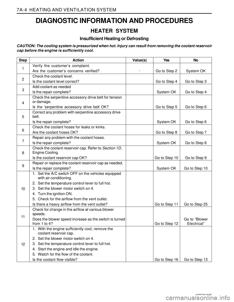
DIAGNOSTIC INFORMATION AND PROCEDURES
HEATER SYSTEM
Insufficient Heating or Defrosting
CAUTION: The cooling system is pressurized when hot. Injury can result from removing the coolant reservoir
cap before the engine is sufficiently cool.
Step
1
2
3
4
5
6
7
8
9
10
11
12
Action
Verify the customer’s complaint.
Are the customer’s concerns verified?
Check the coolant level.
Is the coolant level correct?
Add coolant as needed
Is the repair complete?
Check the serpentine accessory drive belt for tension
or damage.
Is the ’serpentine accessory drive belt OK?
Correct any problem with serpentine accessory drive
belt.
Is the repair complete?
Check the coolant hoses for leaks or kinks.
Are the coolant hoses OK?
Repair any problem with the coolant hoses.
Is the repair complete?
Check the coolant reservoir cap. Refer to Section 1D,
Engine Cooling.
Is the coolant reservoir cap OK?
Repair or replace the coolant reservoir cap as needed.
Is the repair complete?
1. Set the A/C switch OFF on the vehicles equipped
with air conditioning.
2. Set the temperature control lever to full hot.
3. Set the blower motor switch on 4.
4. Turn the ignition ON.
5. Check for the airflow from the vent outlet.
Is there a heavy airflow from the vent outlet?
Check for change in the airflow at various blower
speeds.
Does the blower speed increase as the switch is turned
from 1 to 4?
1. With the engine sufficiently cool, remove the
coolant reservoir cap.
2. Set the blower motor switch on 4.
3. Set the temperature control lever to full hot.
4. Start the engine and idle the engine.
5. Watch for the flow of the coolant.
Is the coolant flow visible?Yes
Go to Step 2
Go to Step 4
System OK
Go to Step 5
System OK
Go to Step 8
System OK
Go to Step 10
System OK
Go to Step 11
Go to Step 12
Go to Step 16No
System OK
Go to Step 3
Go to Step 4
Go to Step 6
Go to Step 6
Go to Step 7
Go to Step 8
Go to Step 9
Go to Step 10
Go to Step 25
Go to “Blower
Electrical”
Go to Step 13 Value(s)
-
Page 1506 of 2053
HEATING AND VENTILATION SYSTEM 7A-5
SSANGYONG MY2002
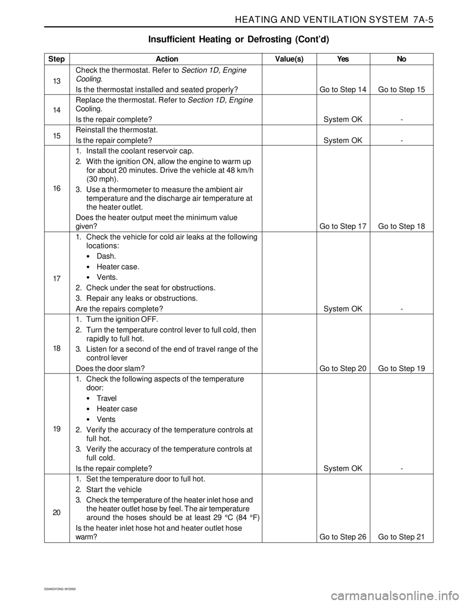
Insufficient Heating or Defrosting (Cont’d)
Step
13
14
15
16
17
18
19
20Action
Check the thermostat. Refer to Section 1D, Engine
Cooling.
Is the thermostat installed and seated properly?
Replace the thermostat. Refer to Section 1D, Engine
Cooling.
Is the repair complete?
Reinstall the thermostat.
Is the repair complete?
1. Install the coolant reservoir cap.
2. With the ignition ON, allow the engine to warm up
for about 20 minutes. Drive the vehicle at 48 km/h
(30 mph).
3. Use a thermometer to measure the ambient air
temperature and the discharge air temperature at
the heater outlet.
Does the heater output meet the minimum value
given?
1. Check the vehicle for cold air leaks at the following
locations:
Dash.
Heater case.
Vents.
2. Check under the seat for obstructions.
3. Repair any leaks or obstructions.
Are the repairs complete?
1. Turn the ignition OFF.
2. Turn the temperature control lever to full cold, then
rapidly to full hot.
3. Listen for a second of the end of travel range of the
control lever
Does the door slam?
1. Check the following aspects of the temperature
door:
Travel
Heater case
Vents
2. Verify the accuracy of the temperature controls at
full hot.
3. Verify the accuracy of the temperature controls at
full cold.
Is the repair complete?
1. Set the temperature door to full hot.
2. Start the vehicle
3. Check the temperature of the heater inlet hose and
the heater outlet hose by feel. The air temperature
around the hoses should be at least 29 °C (84 °F)
Is the heater inlet hose hot and heater outlet hose
warm?Yes
Go to Step 14
System OK
System OK
Go to Step 17
System OK
Go to Step 20
System OK
Go to Step 26No
Go to Step 15
-
-
Go to Step 18
-
Go to Step 19
-
Go to Step 21 Value(s)
Page 1507 of 2053
SSANGYONG MY2002
7A-6 HEATING AND VENTILATION SYSTEM
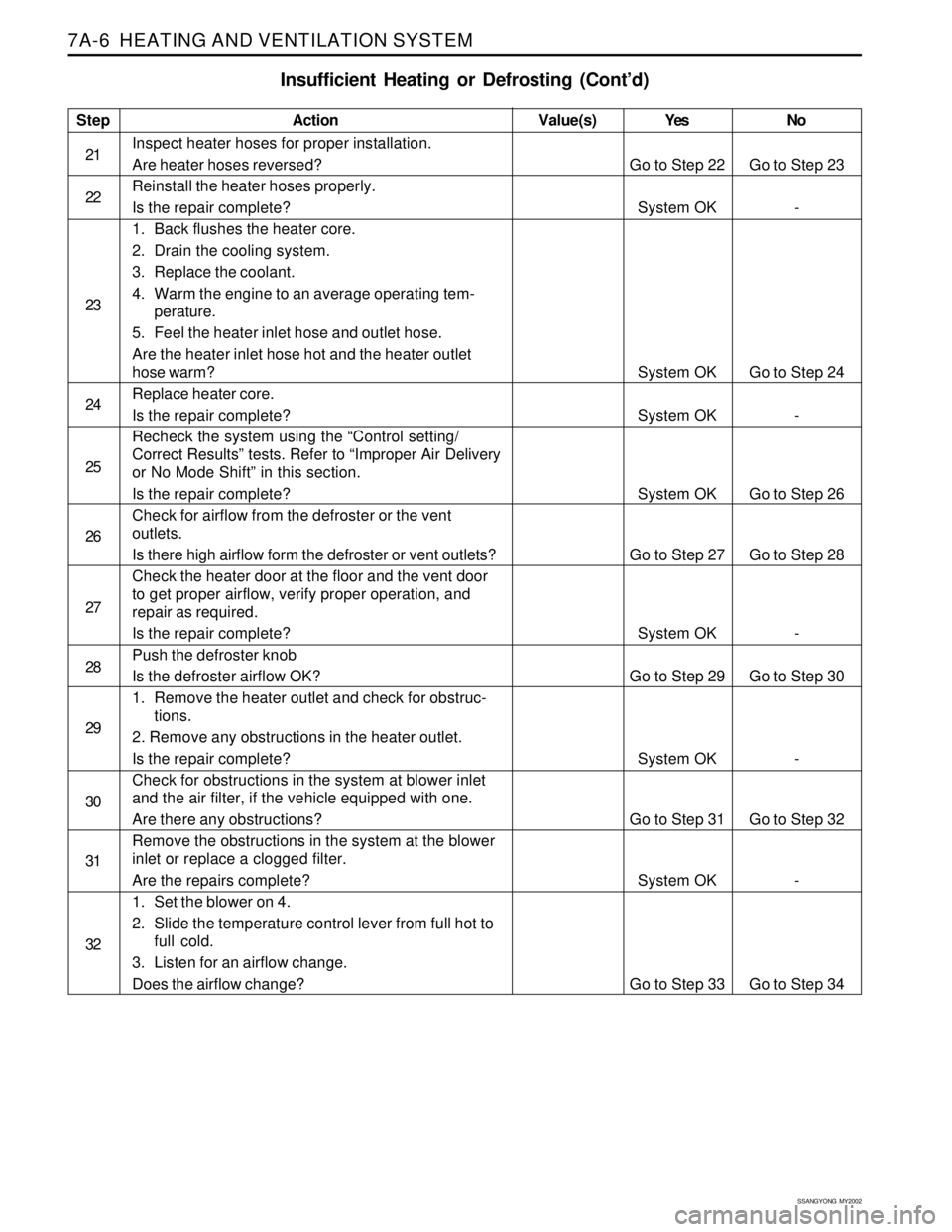
Insufficient Heating or Defrosting (Cont’d)
Step
21
22
23
24
25
26
27
28
29
30
31
32Action
Inspect heater hoses for proper installation.
Are heater hoses reversed?
Reinstall the heater hoses properly.
Is the repair complete?
1. Back flushes the heater core.
2. Drain the cooling system.
3. Replace the coolant.
4. Warm the engine to an average operating tem-
perature.
5. Feel the heater inlet hose and outlet hose.
Are the heater inlet hose hot and the heater outlet
hose warm?
Replace heater core.
Is the repair complete?
Recheck the system using the “Control setting/
Correct Results” tests. Refer to “Improper Air Delivery
or No Mode Shift” in this section.
Is the repair complete?
Check for airflow from the defroster or the vent
outlets.
Is there high airflow form the defroster or vent outlets?
Check the heater door at the floor and the vent door
to get proper airflow, verify proper operation, and
repair as required.
Is the repair complete?
Push the defroster knob
Is the defroster airflow OK?
1. Remove the heater outlet and check for obstruc-
tions.
2. Remove any obstructions in the heater outlet.
Is the repair complete?
Check for obstructions in the system at blower inlet
and the air filter, if the vehicle equipped with one.
Are there any obstructions?
Remove the obstructions in the system at the blower
inlet or replace a clogged filter.
Are the repairs complete?
1. Set the blower on 4.
2. Slide the temperature control lever from full hot to
full cold.
3. Listen for an airflow change.
Does the airflow change?Yes
Go to Step 22
System OK
System OK
System OK
System OK
Go to Step 27
System OK
Go to Step 29
System OK
Go to Step 31
System OK
Go to Step 33No
Go to Step 23
-
Go to Step 24
-
Go to Step 26
Go to Step 28
-
Go to Step 30
-
Go to Step 32
-
Go to Step 34 Value(s)
Page 1540 of 2053
MANUAL & SEMIAUTO-HVAC 7C-11
SSANGYONG MY2002
HEATER SYSTEM
1 Heater-to Defrost Duct
2 Heater Unit
3 Mode Actuator Assembly
4 Heater Controller
5 Side Air Vent6 Coolant Outlet Hose
7 Coolant Inlet Hose
8 Heater-to-Blower Duct
9 Blower Unit
KAA7B450
Page 1555 of 2053
SECTION 7D
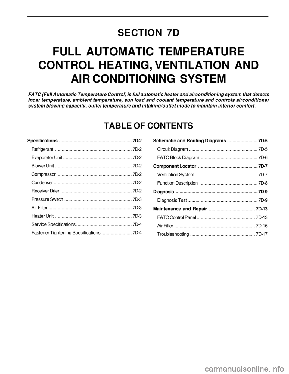
FULL AUTOMATIC TEMPERATURE
CONTROL HEATING, VENTILATION AND
AIR CONDITIONING SYSTEM
FATC (Full Automatic Temperature Control) is full automatic heater and airconditioning system that detects
incar temperature, ambient temperature, sun load and coolant temperature and controls airconditioner
system blowing capacity, outlet temperature and intaking/outlet mode to maintain interior comfort.
TABLE OF CONTENTS
Specifications.......................................................7D-2
Refrigerant..........................................................7D-2
Evaporator Unit....................................................7D-2
Blower Unit..........................................................7D-2
Compressor.........................................................7D-2
Condenser...........................................................7D-2
Receiver Drier......................................................7D-2
Pressure Switch...................................................7D-3
Air Filter...............................................................7D-3
Heater Unit..........................................................7D-3
Service Specifications ..........................................7D-4
Fastener Tightening Specifications.......................7D-4Schematic and Routing Diagrams.......................7D-5
Circuit Diagram....................................................7D-5
FATC Block Diagram...........................................7D-6
Component Locator.............................................7D-7
Ventilation System...............................................7D-7
Function Description............................................7D-8
Diagnosis..............................................................7D-9
Diagnosis Test.....................................................7D-9
Maintenance and Repair................................... 7D-13
FATC Control Panel............................................ 7D-13
Air Filter............................................................. 7D-16
Troubleshooting................................................. 7D-17
Page 1558 of 2053
SSANGYONG MY2002
7D-4 FATC-HAVC
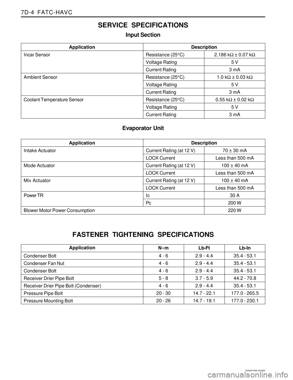
SERVICE SPECIFICATIONS
Input Section
Incar Sensor
Ambient Sensor
Coolant Temperature SensorApplicationDescriptionResistance (25°C)
Voltage Rating
Current Rating
Resistance (25°C)
Voltage Rating
Current Rating
Resistance (25°C)
Voltage Rating
Current Rating
Evaporator Unit
2.186 kΩ ± 0.07 kΩ
5 V
3 mA
1.0 kΩ ± 0.03 kΩ
5 V
3 mA
0.55 kΩ ± 0.02 kΩ
5 V
3 mA
Intake Actuator
Mode Actuator
Mix Actuator
Power TR
Blower Motor Power ConsumptionApplicationDescriptionCurrent Rating (at 12 V)
LOCK Current
Current Rating (at 12 V)
LOCK Current
Current Rating (at 12 V)
LOCK Current
Ic
Pc70 ± 30 mA
Less than 500 mA
100 ± 40 mA
Less than 500 mA
100 ± 40 mA
Less than 500 mA
30 A
200 W
220 W
FASTENER TIGHTENING SPECIFICATIONS
N•m
4 - 6
4 - 6
4 - 6
5 - 8
4 - 6
20 - 30
20 - 26Lb-Ft
2.9 - 4.4
2.9 - 4.4
2.9 - 4.4
3.7 - 5.9
2.9 - 4.4
14.7 - 22.1
14.7 - 19.1 Condenser Bolt
Condenser Fan Nut
Condenser Bolt
Receiver Drier Pipe Bolt
Receiver Drier Pipe Bolt (Condenser)
Pressure Pipe Bolt
Pressure Mounting BoltLb-In
35.4 - 53.1
35.4 - 53.1
35.4 - 53.1
44.2 - 70.8
35.4 - 53.1
177.0 - 265.5
177.0 - 230.1Application
Page 1564 of 2053
SSANGYONG MY2002
7D-10 FATC-HAVC
Self-diagnosis Method
Ignition switch “ON”
Press the intake switch more than 4 times within
2 seconds while pressing the AUTO switch
Self-diagnosis will start after turning off all displays
on VFD for 2.5 seconds
Self-diagnosis items check
(continuous action)
Airconditioner control
Self-diagnosis items check
(step action)
Press AUTO Press AUTOPress OFF
Press OFF
Diagnosis Item and Fault Code
15 : coolant Sensor Open
16 : coolant Sensor Short
17 : temperature Actuator Open/Short
18 : temperature Actuator Drive Fault 00 : normal
11 : incar Sensor Open
12 : incar Sensor Short
13 : ambient Sensor Open
14 : ambient Sensor Short